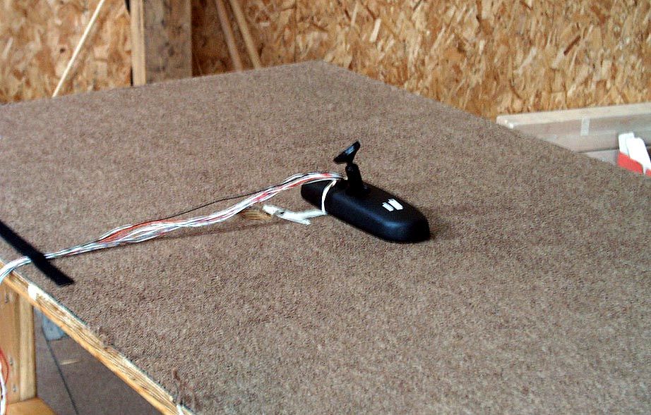
NZLBTPHL3Universal Garage Door Opener in Mirror
Gentex Corporation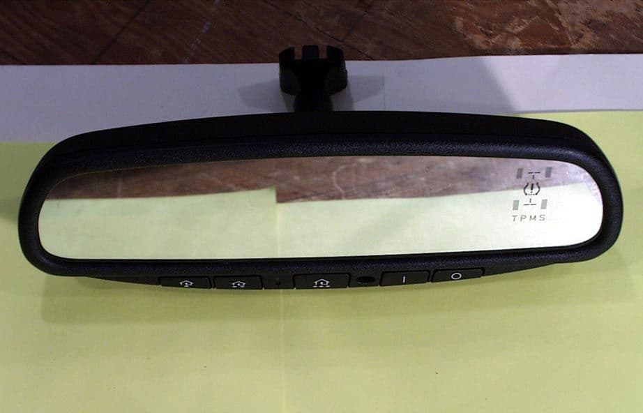
Click to zoom
Application Details
- Equipment Class
- DSR - Part 15 Remote Control/Security Device Transceiver
- Date of Grant
- Mar 09, 2004
- Application Purpose
- Original Equipment
- Date of Application
- Jan 04, 2004
- Equipment Note
- Universal Garage Door Opener in Mirror
- Frequency Range
- 410.00000000 - 420.00000000
- Company
- Gentex Corporation
- Country
- United States
Documents & Files
Document Text
Text extracted from the exhibit documents filed with the FCC. Open a document above to read the original.
Users Manual
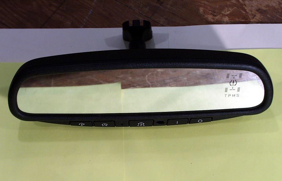
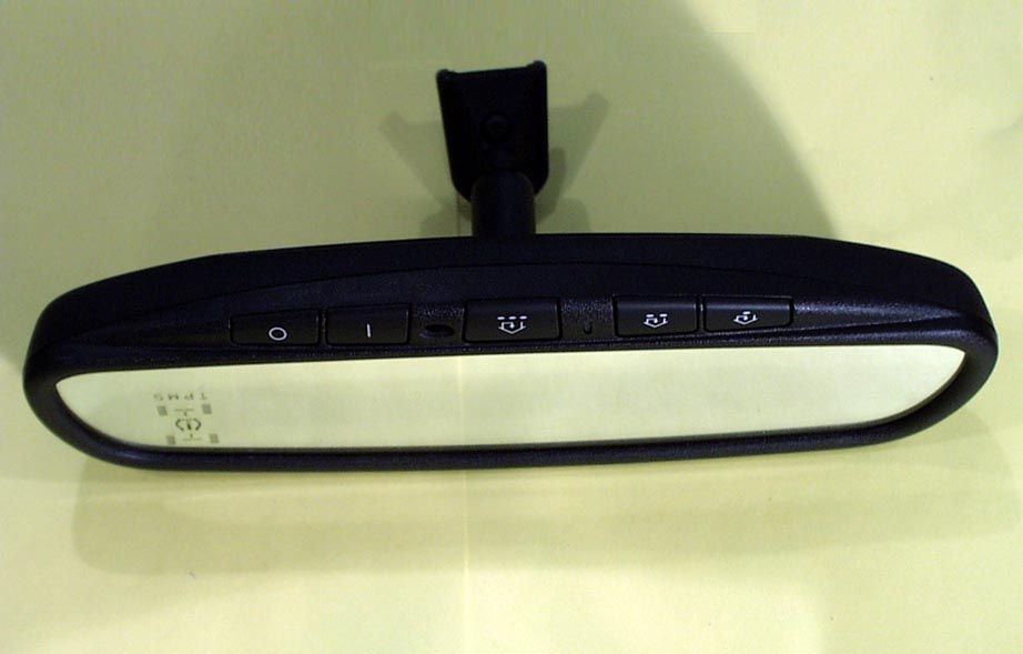
Homelink ® Mirror Your new vehicle comes with an Automatic-Dimming Mirror with an Integrated Homelink Wireless Control System. Optional Tire Pressure Monitor Indicators: See your Owners Manual Glare Detection Senso r Indicator Light HomeLink Buttons Automatic-Dimming Function Automatic-Dimming Mirror Function Buttons During nighttime driving, this safety feature will automatically detect and eliminate dangerous rearview mirror glare. To protect your vision during nighttime driving, your mirror will automatically dim upon detecting glare from the vehicles traveling behind you. Press the button to turn the automatic-dimming function off. The mirror indicator light will turn off. Press the button to turn the automatic-dimming function on. The mirror indicator light will illuminate. NOTE: The mirror defaults to the "on" position each time the vehicle is started. Homelink Programming Guide The HomeLink Wireless Control System provides a convenient way to replace up to three hand-held radio-frequency (RF) transmitters used to activate devices such as gate operators, garage door openers, entry door locks, security systems, even home lighting. Additional HomeLink information can be found at: www.homelink.com or by calling 1-800-355-3515. PrecautionsPrecautions! Before programming HomeLink to a garage door opener or gate operator, make sure that people and objects are out of the way of the device to prevent potential harm or damage. When programming a garage door opener, it is advised to park outside of the garage. Do not use HomeLink with any garage door opener that lacks safety stop and reverse features as required by U.S. federal safety standards (this includes any garage door opener model manufactured before April 1, 1982). A garage door that cannot detect an object - signaling the door to stop and reverse - does not meet current U.S. federal safety standards. For more information, contact HomeLink at www.homelink.com or by calling: 1–800–355–3515. Retain the original transmitter of the RF device you are programming for use in other vehicles as well as for future HomeLink programming. It is also suggested that upon the sale of the vehicle, the programmed HomeLink buttons be erased for security purposes. Refer to “Programming” (step #1 only) or, for assistance, contact HomeLink at: www.homelink.com or by calling: 1-800-355-3515. Programming HomeLink Note: Some vehicles may require the ignition switch to be turned to the second (or “accessories”) position for programming and/or operation of HomeLink. It is also recommended that a new battery be placed in the hand-held transmitter of the device being programmed to HomeLink for quicker training and accurate transmission of the radio-frequency signal. 1. Press and hold the two outer HomeLink buttons - releasing only when the indicator light begins to flash (after 20 seconds). Do not hold the buttons for longer than 30 seconds and do not repeat step one to program a second and/or third hand-held transmitter to the remaining two HomeLink buttons. Flashing Flashing 2. Position the end of your hand-held transmitter 1–3 inches (5–14 cm) away from the HomeLink buttons while keeping the indicator light in view. Transmitter 1-3 inches 3. Simultaneously press and hold both the HomeLink and hand- held transmitter button. Do not release the buttons until step 4 has been completed. (Note: Some gate operators and garage door openers may require you to replace this Programming Step 3 with procedures noted in the “Gate Operator and Canadian Programming” section.) 4. The indicator light will flash slowly and then rapidly after HomeLink successfully receives the frequency signal from the hand-held transmitter. Release both buttons. 5. Press and hold the just-trained HomeLink button and observe the indicator light. If the indicator light stays on constantly, programming is complete and your device should activate when the HomeLink button is pressed and released. Note: To program the remaining two HomeLink buttons, begin with “Programming” - step two. Do not repeat step one. If the indicator light blinks rapidly for two seconds and then turns to a constant light, continue with “Programming” - steps 6-8 to complete the programming of a rolling code equipped device (most commonly a garage door opener). 6. At the garage door opener receiver (motor-head unit) in the garage, locate the “learn” or “smart” button. This can usually be found where the hanging antenna wire is attached to the motor-head unit. 7. Firmly press and release the “learn” or “smart” button. (The name and color of the button may vary by manufacturer.) Note: There are 30 seconds in which to initiate step eight. 8. Return to the vehicle and firmly press, hold for two seconds and release the programmed HomeLink button. Repeat the “press/hold/release” sequence a second time, and, depending on the brand of the garage door opener (or other rolling code equipped device), repeat this sequence a third time to complete the programming. HomeLink should now activate your rolling code equipped device. Note: To program the remaining two HomeLink buttons, begin with “Programming” - step two. Do not repeat step one. For questions or comments, please contact HomeLink at: www.homelink.com or 1–800–355–3515. Gate Operator & Canadian Programming Canadian radio-frequency laws require transmitter signals to “time-out” (or quit) after several seconds of transmission – which may not be long enough for HomeLink to pick up the signal during programming. Similar to this Canadian law, some U.S. gate operators are manufactured to “time-out” in the same manner. If you live in Canada or you are having difficulties programming a gate operator by using the “Programming” procedures (regardless of where you live), replace “Programming HomeLink” Step 3 with the following: Note: If programming a garage door opener or gate operator, it is advised to unplug the device during the “cycling” process to prevent possible overheating. 3. Continu…
Text truncated - open the document above for the full version.
Cover Letter(s)
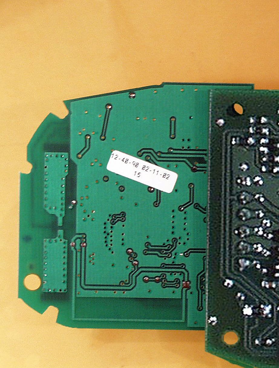
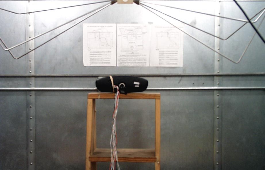
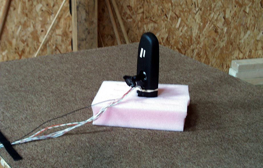
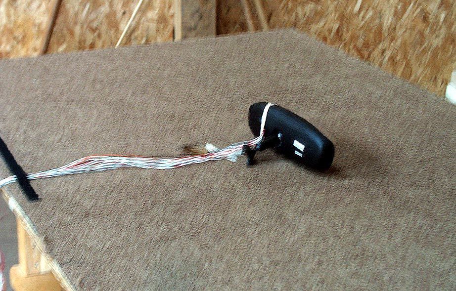
AHD EMC Lab, 92723 M152, Dowagiac, MI 49047, (616) 424-7014 386024.DOC Request for CONFIDENTIALITY and COVER Letter: Page 1 of 2 NVLAP ACCREDITED NARTE Certified Engineer Professional Engineer Federal Communications Commission Equipment Approval Services, P.O. Box 358315 Pittsburgh, PA 15251-5315 Attention: Authorization & Evaluation Division Re: Application for Certification of Gentex Corporation Transmitter under 47CFR 15.231. FCC ID: NZLBTPHL3 Gentlemen: On behalf of the applicant, Gentex Corporation, please find attached the submittal materials for certification of the Universal Garage Door Opener transceiver in an NVSX Mirror with Tire Pressure Monitor Indicators. The model is NZLBTPHL3. This unit is capable of learning the current garage door transmit frequencies from 288MHz through 420MHz except in the forbidden frequency regions. Pursuant to 47CRF 0.459, Gentex Corporation requests that these listed exhibits be held confidential . Circuit Block Diagrams Two ‘pdf’ documents of Exhibit B Theory/Description of Operation, “operation.doc” of Exhibit B Schematics Five ‘pdf’ documents of Exhibit B Gentex Corporation has invested considerable resources into developing this product. Having sections of Exhibit B, listed above, available to ‘competition’ would negate the advantage achieved in developing this product. Since this product type is a major product line for Gentex Corporation, not protecting the details of the design would result in a financial hardship for the company. The complete List of the Exhibits in this submittal package appears on Page 2 of this cover letter. The Federal Communications Commission will be notified, in writing, of any changes in the software/programming of the device that could affect the device’s RF characteristics. A copy of a ‘Power of Attorney” is included to demonstrate that AHD has been authorized to provide the service of preparing this application. Your prompt consideration of this application for product certification will be greatly appreciated. Should you have any questions regarding the content of this report, kindly contact me. Sincerely, Ted Chaffee, Technical Lab Manager Narte Certified Engineer, #EMC-002025-NE tel/fax: 616. 424.7014 email: [email protected] Test report #0300647F FCC 15.231 for NZLBTPHL3 FCC ID: NZLBTPHL3 Tested October 23, 2003 AHD EMC Lab, 92723 M152, Dowagiac, MI 49047, (616) 424-7014 386024.DOC Cover / Confidentiality Request Letter: Page 2 of 2 Table of Contents Cover Letter / Table of Contents Total Pages 2 EXHIBIT A: ID Label / Location [2.925,2.926,2.1033(b2,7),15.19(a3)] Total Pages 2 EXHIBIT B: Description of Product [2.1033(b6)] EXB_EUTdesc.doc Total Pages 1 Description of Operation [2.1033(b4)] EXB_operation.doc Total Pages 2 Circuit Block Diagram [2.1033(b5)] EXB_Blockdia1.pdf, EXB_Blockdia2.pdf Total Pages 2 Schematics [2.1033(b5)] EXB_RFschem.pdf, EXB_microProc.pdf EXB_ButtonSchem.pdf, EXB_TPMIndDriver.pdf, EXB_TPMindicator.pdf Total Pages 5 EXHIBIT C: Product photos eight photos Total Pages 9 : Interior & Printed Circuit Boards [2.1033(b7)] Five photos EXC_3PCBtop.jpg, EXC_3PCBbtm.jpg, EXC_HL3PCBtop.jpg, EXC_HL3PCBbtm.jpg, EXC_InMirror.jpg Exterior views [2.1033(b7)] Three photos EXC_Mirrorfrnt.jpg, EXC_Mirrorrear.jpg, EXC_Mirrorbtm.jpg EXHIBIT D: User’s Manual EXD_OwnerManual.pdf Total Pages 4 EXHIBIT E: Setup photos [2.1033(b8)] Four photos Total Pages 5 EXE_pretest.jpg, EXE_side.jpg, EXE_end.jpg, EXE_flat.jpg Report of Measurements [2.1033(b6)] Total Pages 28 Table of Contents Page 2 Manufacturer/Applicant [2.1033(b1)] Page 4 Measurement/Test Facility & Equipment Page 4 Configuration/Setup [2.1033(b8)] Page 5 Test Standards / Methods Used [2.1033(b6)] Page 8 Test Methodology [2.1033(b6)] Page 8 Test Data [2.1033(b6)] Summary of Results Page 6 Level vs Supply Voltage [15.31(e)] Page 14 Occupied Bandwidth Page 15 Radiated Field Strength [15.231(b)] Page 17 Misc. EXHIBIT: RF Exposure Information [2.1093(c)] Total Pages 1 Tune-up Information [2.1033(b5] Total Pages 1
Cover Letter(s)
AHD EMC Lab, 92723 M152, Dowagiac, MI 49047, (616) 424-7014 402969 Request for CONFIDENTIALITY: Page 1 of 1 NVLAP ACCREDITED NARTE Certified Engineer Professional Engineer Federal Communications Commission Equipment Approval Services, P.O. Box 358315 Pittsburgh, PA 15251-5315 Attention: Authorization & Evaluation Division Re: Application for Certification of Gentex Corporation Transmitter under 47CFR 15.231. FCC ID: NZLBTPHL3 731 Confirmation Number EA762752 Correspondence reference number: 26468 Gentlemen: Pursuant to 47CRF 0.459, Gentex Corporation requests that these listed exhibits be held confidential . Circuit Block Diagrams file names: EXB_Blockdia1.pdf; EXB_Blockdia2.pdf Theory/Description of Operation, file name: EXB_operation.doc Schematics file names: EXB_ RFschem.pdf; EXB_microProc.pdf; EXB_ ButtonSchem.pdf; EXB_TPMIndDriver.pdf EXB_TPMindicator.pdf Gentex Corporation has invested considerable resources into developing this product. Having sections of Exhibit B, listed above, available to ‘competition’ would negate the advantage achieved in developing this product. Since this product type is a major product line for Gentex Corporation, not protecting the details of the design would result in a financial hardship for the company. The Federal Communications Commission will be notified, in writing, of any changes in the software/programming of the device that could affect the device’s RF characteristics. Your prompt consideration of this application for product certification will be greatly appreciated. Should you have any questions regarding the content of this report, kindly contact me. Sincerely, Ted Chaffee, Technical Lab Manager Narte Certified Engineer, #EMC-002025-NE tel/fax: 616. 424.7014 email: [email protected]
ID Label/Location Info
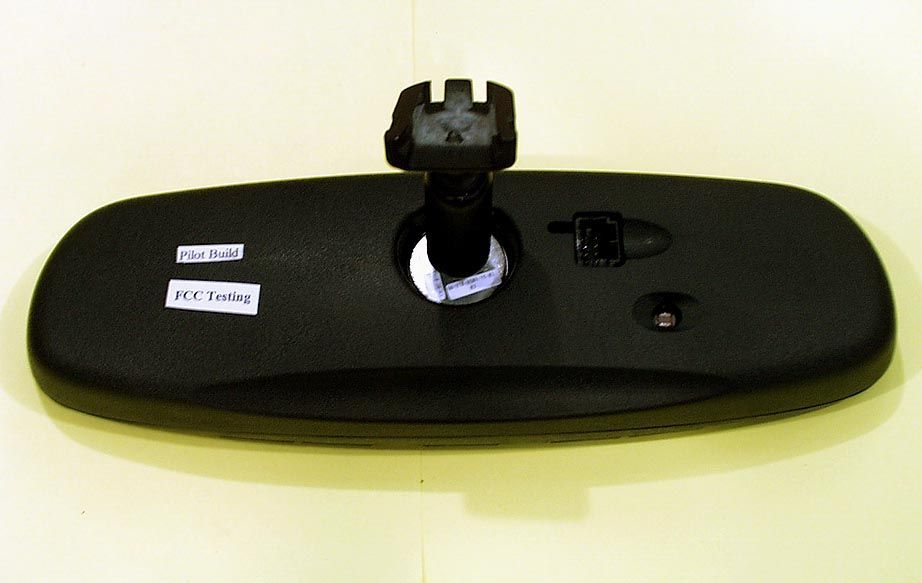
Test report #0300647F FCC 15.231 for NZLBTPHL3 FCC ID: NZLBTPHL3 Tested October 23, 2003 AHD EMC Lab, 92723 M152, Dowagiac, MI 49047, (616) 424-7014 386026.DOC Exhibit A: Page 1 of 2 EXHIBIT A: EQUIPMENT LABEL [2.925, 2.926, 2.1033(B2,7), 15.19(A3)] LABEL EXAMPLE For the label Information refer to picture file “EXA_LabelLocation.pdf” The FCC Identifier assigned to the EUT is FCC ID: NZLBTPHL3. This number will be molded into the rear of the mirror housing. Because of the size and location of the transmitter portion of the product, the following statements will appear in the user’s manual. Refer to Exhibit D for the entire text of the user’s manual. “This device complies with FCC rules Part 15. Operation is subject to the following two conditions: (1) This device may not cause harmful interference, and (2) This device must accept any interference that may be received including interference that may cause undesired operation. WARNING: The transmitter has been tested and complies with FCC and Industry Canada rules. Changes or modifications not expressly approved by the party responsible for compliance could void the user’s authority to operate the device.” FCC ID Number LOCATION The information will be molded onto the outside of the NZLBTPHL3 plastic housing.
RF Exposure Info
Test report #0300647F FCC 15.231 for NZLBTPHL3 FCC ID: NZLBTPHL3 Tested October 23, 2003 AHD EMC Lab, 92723 M152, Dowagiac, MI 49047, (616) 424-7014 386075.DOC Misc. EXHIBIT: Page 1 of 2 MISC. EXHIBIT: RF EXPOSURE INFORMATION [2.1093(C)] The manufacturer and applicant: GENTEX CORPORATION 600 N. Centennial St. Zeeland, Michigan 49464 Product: NVSX Mirror with Homelink® III Universal Garage Door Opener with Tire Pressure Monitor Indicators. lighting for vehicle interior. Model: NZLBTPHL3 Applicable Rules: 47CFR Part 15.231 Pursuant to 47CFR Part 1.1307(b), 47CFR Part 2.1091(c), and 47CFR Part 2.1093(c) this transmitting device, compliant to 47CFR Part 15.231, is categorically excluded from evaluation regarding the Maximum Permissible Exposure of RF energy.
Test Report
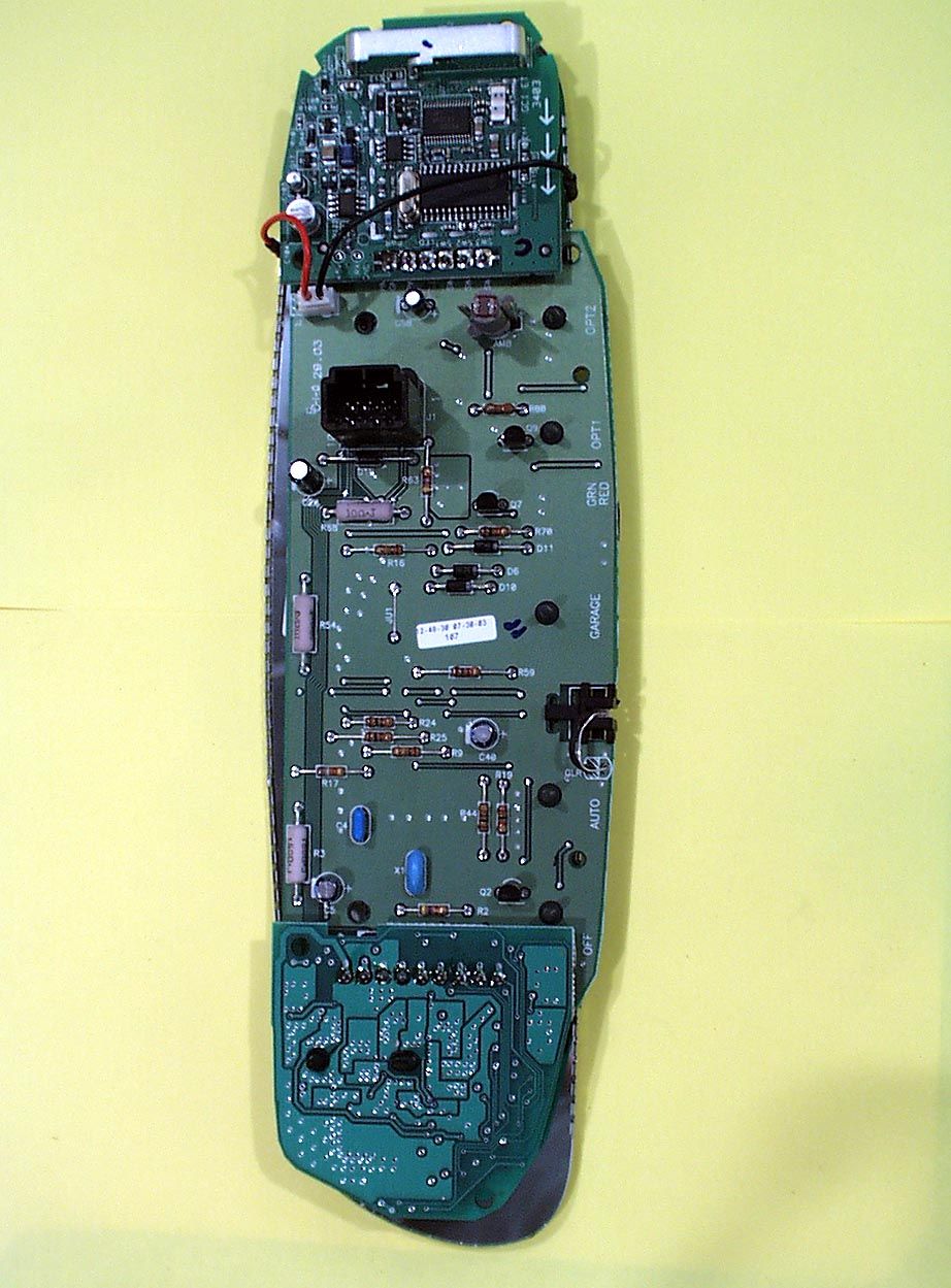
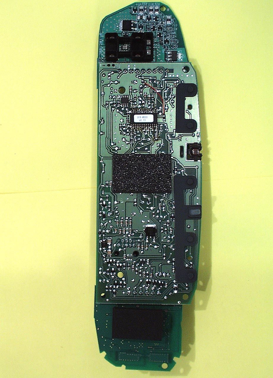
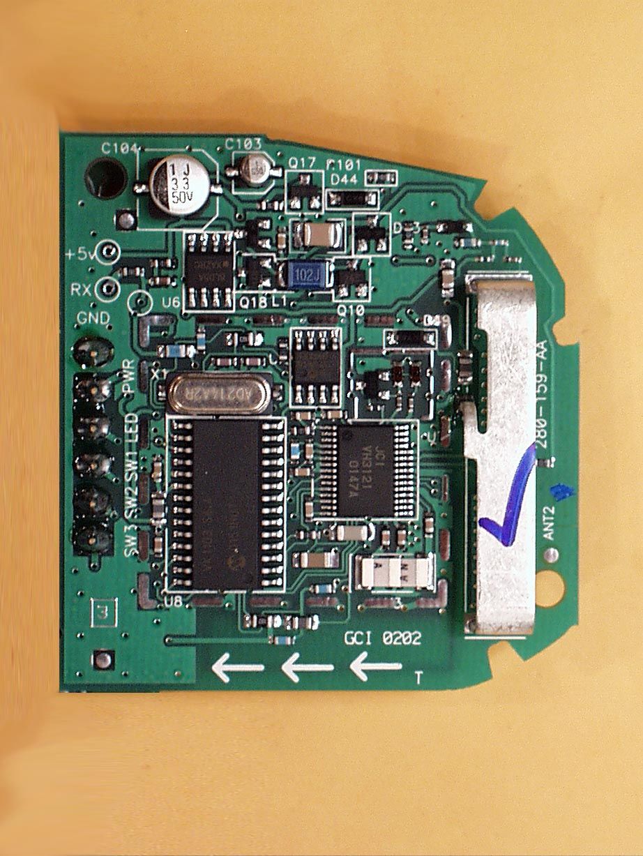
Automatic – Dimming NVS Mirror with Homelink and Tire Pressure Monitor Display Product Description The Automatic Dimming NVSX Mirror with Homelink8 III Universal Garage Door Opener is designed to reduce nuisance glare to the driver’s eyes. The glare is controlled with an electrochromic mirror element that is driven by a microcontroller where dimming levels are determined based on inputs from light sensors monitoring both ambient light in front of the vehicle and glare light from behind the vehicle. This model is also equipped with a Tire Pressure Monitoring System (TPMS) Display that indicates low tire pressure or TPMS system warning. The Homelink8 III is a low-power transceiver device that is installed into the rearview mirror of the automobile and powered by the 12volt system of the automobile. The installation is provided by trained technicians during the course of the manufacturer of the automobile. This Universal Garage Door Opener has the capability to: 1. Learn the frequency and bit code format of the user’s existing garage door remote control devices and 2. Reproduce and transmit the frequency and bit code format to remotely operate the user’s garage door. The unit is designed for the periodic operation of a control signal which activates typically a garage door. The Homelink8 III printed circuit board (PCB) is permanently joined to the main mirror printed circuit board. The mirror PCB contains the three user push buttons and a light emitting diode (LED). This three- button Homelink® unit replaces up to three hand-held transmitters. In addition to the typical operation of the garage door, the unit will learn the radio frequency codes of other transmitter types to activate entry door locks, estate gates, security systems, and home or office lighting. The transmit unit is only operational when the user depresses one of the three control buttons. This unit becomes inactive after release of the control button. The antenna system is an integral part of the unit. It cannot be altered nor replaced by the user. Service of this system is only available from the Automobile Manufacturer’s Dealerships and GENTEX Corporation. The TPMS printed circuit board (PCB) is permanently joined to the main mirror printed circuit board. The activation signals are provided by the vehicle Tire Pressure Monitoring System. No user input is necessary or available.
Test Report
Test report #0300647F FCC 15.231 for NZLBTPHL3 FCC ID: NZLBTPHL3 Tested October 23, 2003 AHD EMC Lab, 92723 M152, Dowagiac, MI 49047, (616) 424-7014 386074.DOC EXHIBIT E: Page 1 of 28 EXHIBIT E: REPORT OF MEASUREMENTS [2.1033(B6)] Test Report for FCC ID: NZLBTPHL3 FCC Part 2.1031, Part 15 Subpart C(15.231) Report #0300647F Issued 12/31/03 MODEL NZLBTPHL3 NVSX MIRROR WITH HOMELINK8 III TRANSCEIVER, & TIRE PRESSURE MONITOR INDICATORS Prepared for: Mr. Colin Carpenter Gentex Corporation 600 N. Centennial St. Zeeland, MI 49464 Test Date(s): October 22-23, 2003 data recorded by witnessed by Ted Chaffee, NCE Colin Carpenter Test Engineer, AHD This report prepared by: Ted Chaffee, NCE Technical Manager/Test Engineer, AHD Test report #0300647F FCC 15.231 for NZLBTPHL3 FCC ID: NZLBTPHL3 Tested October 23, 2003 AHD EMC Lab, 92723 M152, Dowagiac, MI 49047, (616) 424-7014 386074.DOC EXHIBIT E: Page 2 of 28 TABLE OF CONTENTS EXHIBIT E: Report of Measurements [2.1033(b6)] .....................................................................................1 TABLE OF CONTENTS.........................................................................................................................2 Statements Concerning this Report.......................................................................................................3 Manufacturer/Applicant [2.1033(b1)] ....................................................................................................4 Measurement/Test Site Facility & Equipment........................................................................................4 Test Site [2.948, 2.1033(b6)] ......................................................................................................4 Measurement Equipment Used [2.947(d), 15.31(b)] ....................................................................4 Tested Configuration /Setup: [2.1033(b8)] ............................................................................................5 Support Equipment & Cabling .......................................................................................................5 Setup Diagram ...............................................................................................................................5 Description of Equipment Under Test............................................................................................6 Summary of Results: .............................................................................................................................6 Changes made to achieve compliance..........................................................................................8 Standards Applied to Test: [2.1033(b6)]................................................................................................8 Test Methodology: [2.1033(b6)].............................................................................................................8 FORMULAS AND SAMPLE CALCULATIONS: ...........................................................................10 Test Data [2.1033(b6)].........................................................................................................................12 Modulation Characteristics ..........................................................................................................12 Relative Emission Level vs. Supply Voltage [15.31(e)] ...............................................................14 Occupied Bandwidth [15.231(c)]..................................................................................................15 Restricted Bands: [15.205]..........................................................................................................16 Radiated Field Strength Measurements: [15.231(b), 15.205] ....................................................17 Radiated Field Strength Measurements ......................................................................................19 Test report #0300647F FCC 15.231 for NZLBTPHL3 FCC ID: NZLBTPHL3 Tested October 23, 2003 AHD EMC Lab, 92723 M152, Dowagiac, MI 49047, (616) 424-7014 386074.DOC EXHIBIT E: Page 3 of 28 Statements Concerning this Report NVLAP Accreditation: NVLAP Lab Code 200129-0 The scope of AHD accreditation is the conducted emissions, radiated emissions test methods of: IEC/CISPR 22: Limits and methods measurement of radio disturbance characteristics of information technology equipment. FCC Method – 47 CFT Part 15 – Digital Devices. AS/NZS 3548: Electromagnetic Interference – Limits and Methods of Measurement of Information Technology Equipment. IEC61000-4-2 and Amend.1: ElectroStatic Discharge Immunity Test Data: This test report contains data covered by the NVLAP accreditation. Subcontracted Testing: This report does not contain data produced under subcontract. Test Traceability: The calibration of all measuring and test equipment and the measured data using this equipment are traceable to the National Institute for Standards and Technology (NIST). Limitations on results: The test results contained in this report relate only to the Item(s) tested. Any electrical or mechanical modification made to the test item subsequent to the test date shall invalidate the data presented in this report. Any electrical or mechanical modification made to the test item subsequent to this test date shall require an evaluation to verify continued compliance. Limitations on copying: This report shall not be reproduced, except in full, without the written approval of AHD. Limitations of the report: This report shall not be used to claim product endorsement by NVLAP, FCC, or any agency of the US Government. Statement of Test Results Uncertainty: Following the guidelines of NAMAS publication NIS81 and NIST Technical Note 1297, the Measurement Uncertainty at a 95% confidence level is determined to be: ± 1.4 dB Test report #0300647F FCC 15.231 for NZLBTPHL3 FCC ID: NZLBTPHL3 Tested October 23, 2003 AHD EMC Lab, 92723 M152, Dowagiac,…
Text truncated - open the document above for the full version.
Contact Information
Applicant
Brian Miller(Corporate Labs Group Leader - Wireless Regulatory)
Technical Contact
GENTEX CorpColin Carpenter
[email protected]616-772-1800
600 N. Centennial St. · Zeeland, Michigan · United States
Non-Technical Contact
AHD EMC LabTed Chaffee
[email protected]269-424-7014
Test Firm
AHD EMC LaboratoryGordon Helm
Technical Specifications
| # | Rule Parts | Frequency Range | Power Output |
|---|---|---|---|
| 3 | 15.231 | 410 MHz - 420 MHz | - |
Other Applications from Gentex Corporation
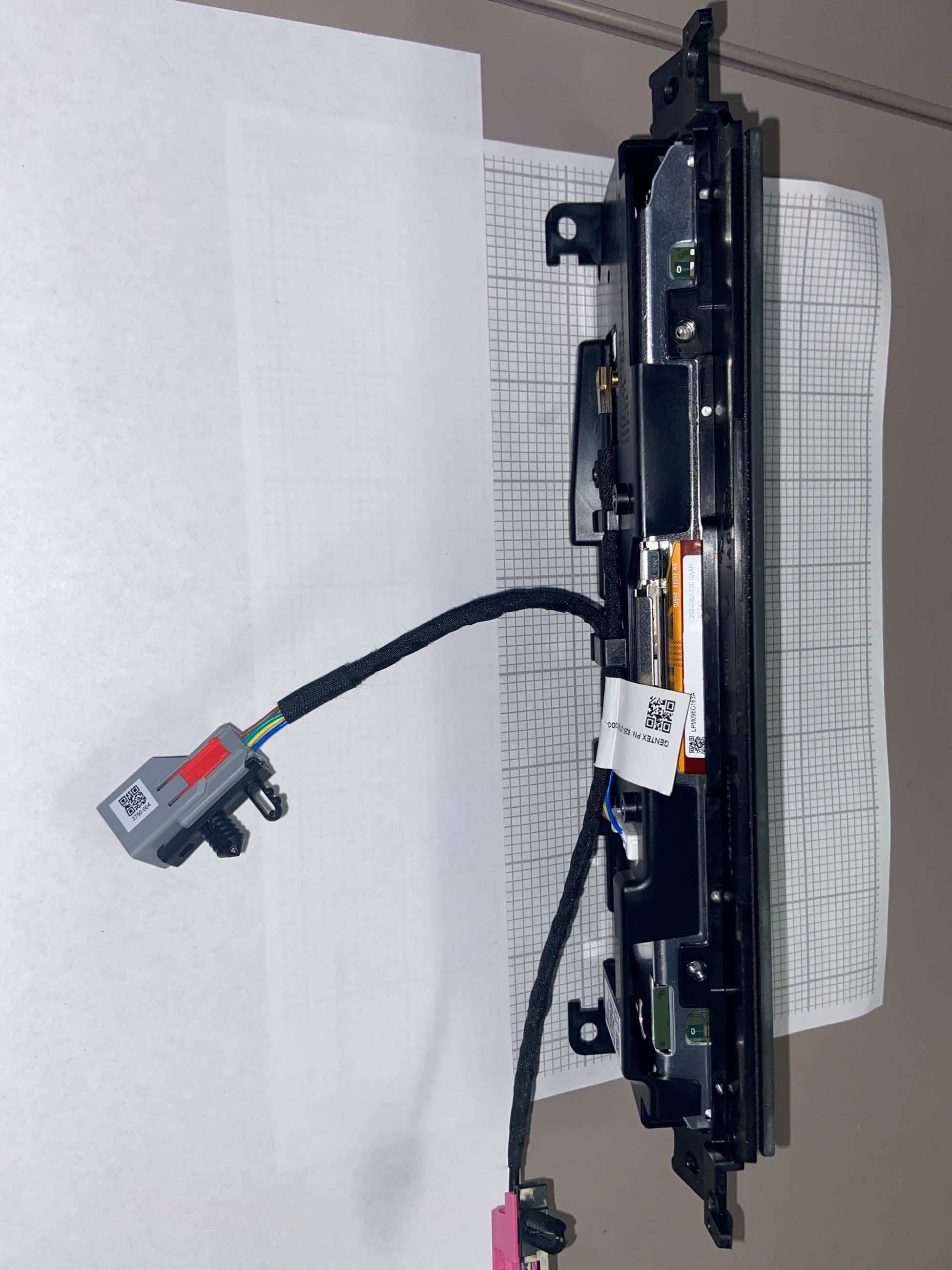
NZLRDHL6A
Jul 29, 2026Wireless Garage Door Opener
Equipment Class
CYY - Communications Receiver used w/Pt 15 Transmitter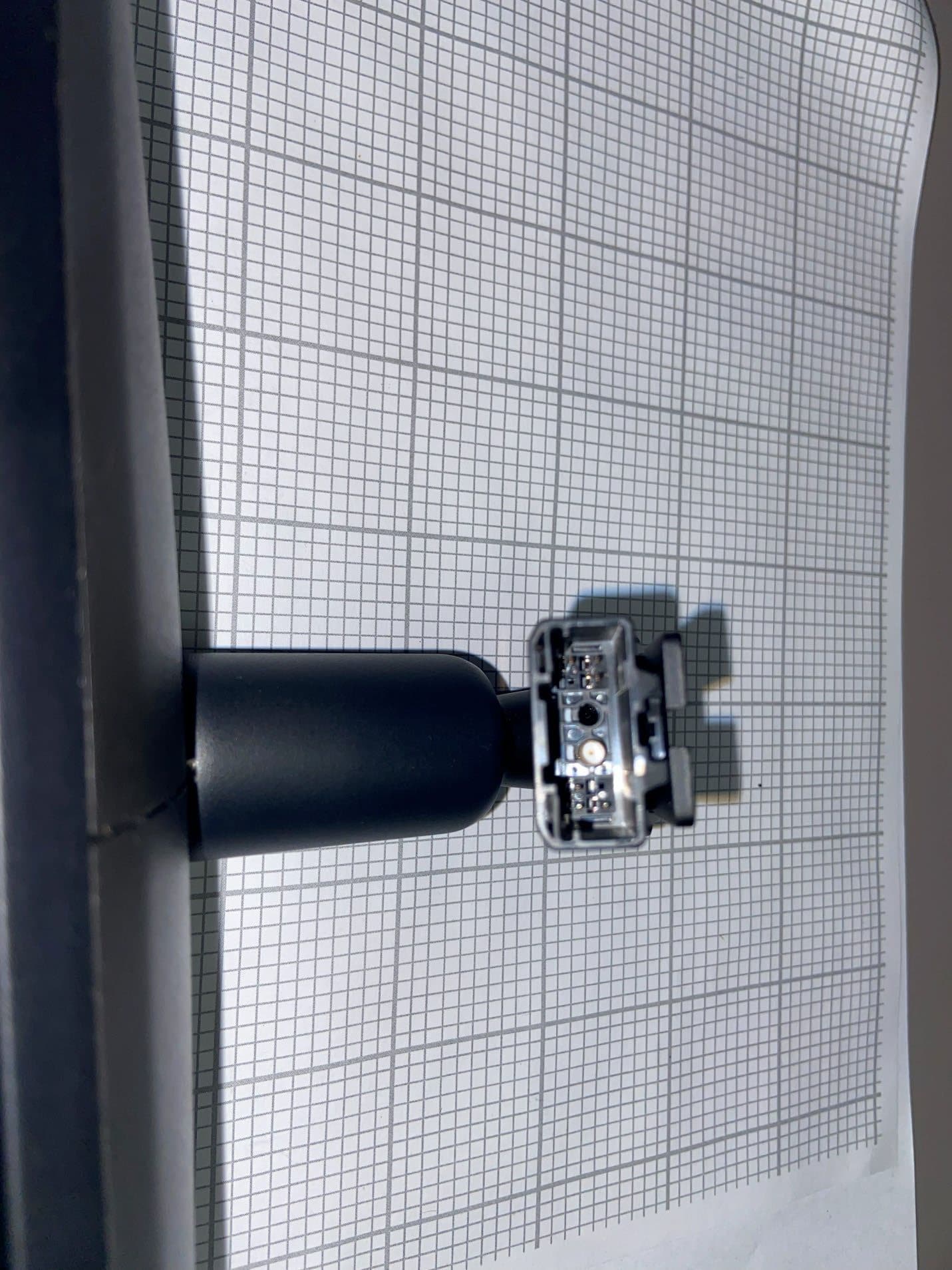
NZLFDMHL6D
Jun 15, 2026Wireless Garage Door Opener
Equipment Class
DTS - Digital Transmission System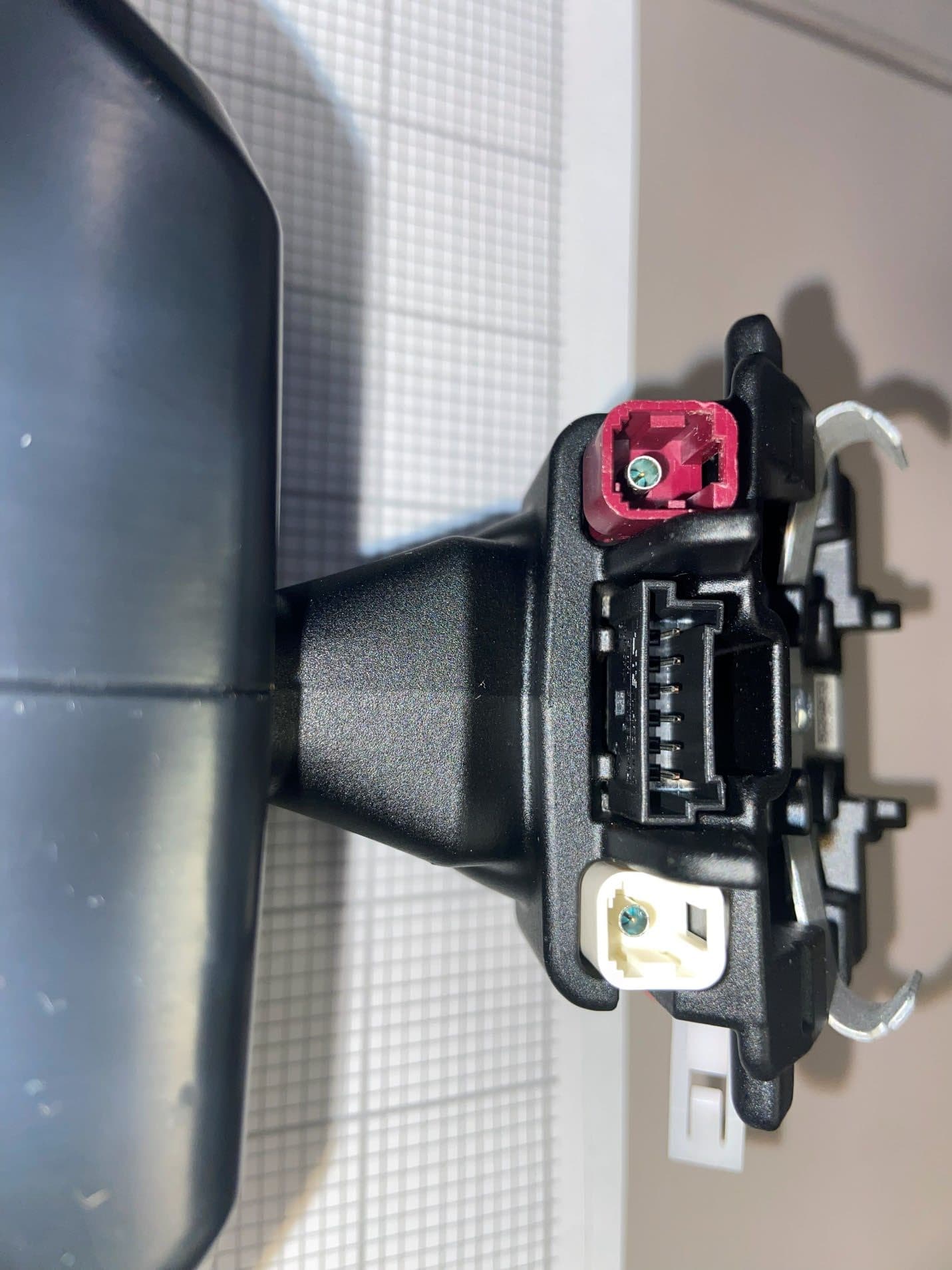
NZLFDMHL6B
May 18, 2026Wireless Garage Door Opener
Equipment Class
DSS - Part 15 Spread Spectrum Transmitter
NZLDEFRX6
May 04, 2026Default Receiver
Equipment Class
DTS - Digital Transmission System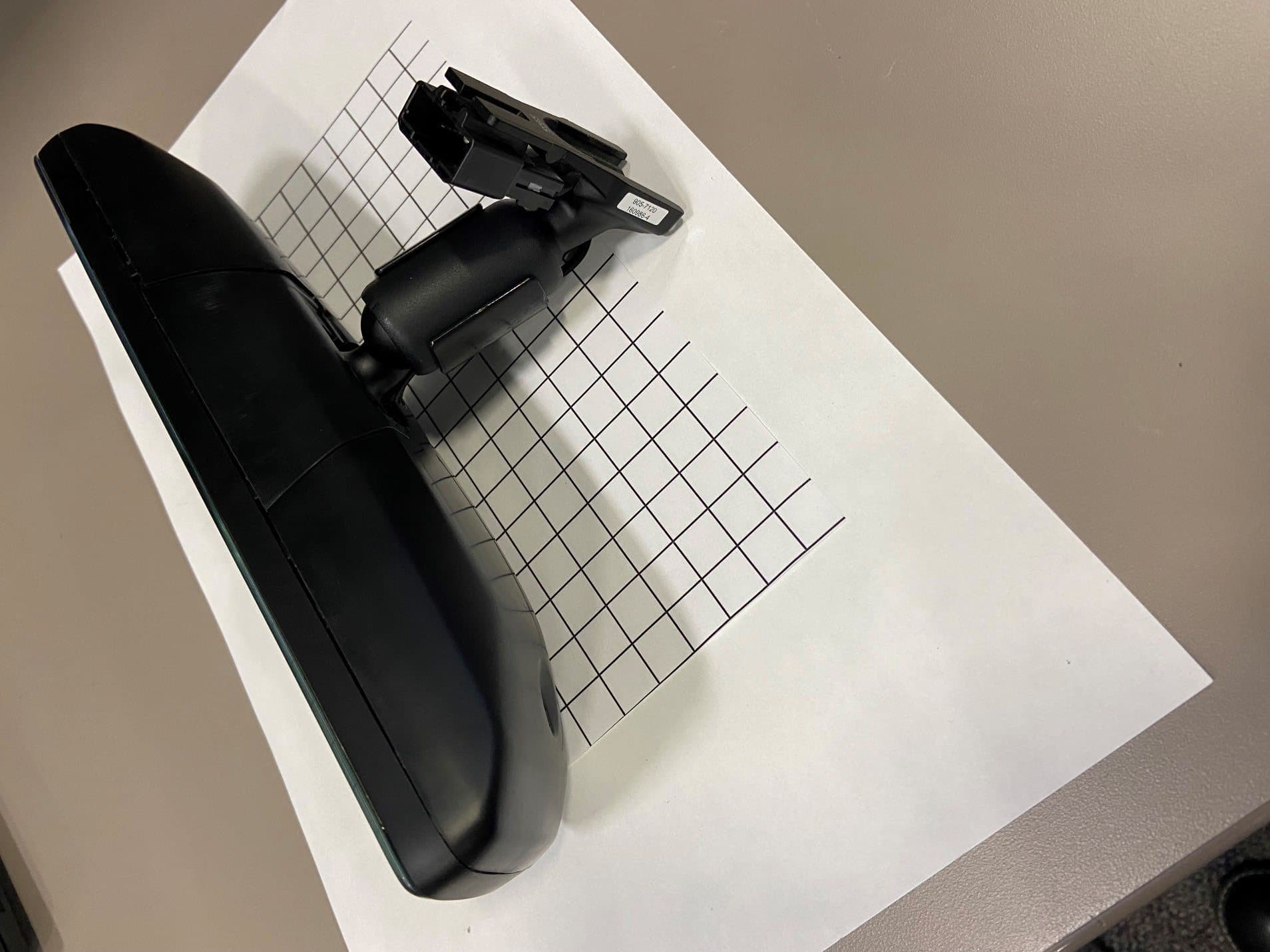
NZLFDMHL6A
Jan 12, 2026Wireless Garage Door Opener
Equipment Class
DTS - Digital Transmission System