NZLDEFRX6Default Receiver
Gentex Corporation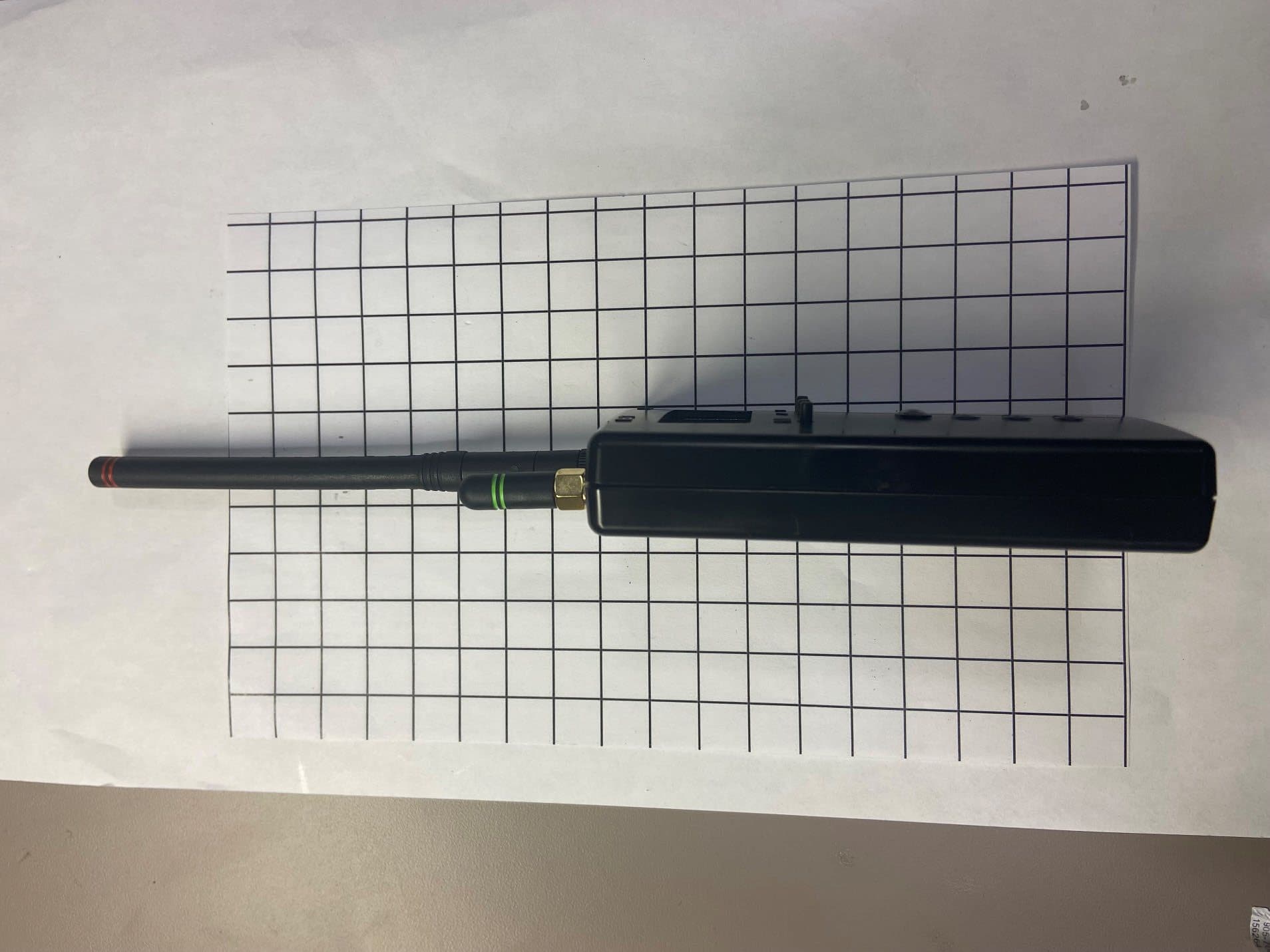
Click to zoom
Application Details
- Equipment Class
- DTS - Digital Transmission System
- Date of Grant
- May 04, 2026
- Application Purpose
- Original Equipment
- Equipment Note
- Default Receiver
- Frequency Range
- 2402.00000000 - 2480.00000000
- Company
- Gentex Corporation
- Country
- United States
Documents & Files
Document Text
Text extracted from the exhibit documents filed with the FCC. Open a document above to read the original.
Users Manual
1 HomeLink® Default Receiver Manual Setup and Instructions Applicable Module Version(s): Hardware: 004 Software: 2.18 ©2025 Gentex Corporation HomeLink® and the HomeLink House® logo are registered trademarks of Gentex Corporation. Bluetooth® is a registered trademark of the Bluetooth SIG, Inc. 2 Contents Document Revision Control & Updates ......................................................................................................... 2 Device Warnings ............................................................................................................................................ 3 Operating Ranges .......................................................................................................................................... 3 Description .................................................................................................................................................... 4 Connections ................................................................................................................................................... 6 Set Up ............................................................................................................................................................ 7 Power Supply ............................................................................................................................................. 7 Software Versions ..................................................................................................................................... 7 Attach the Antennas .................................................................................................................................. 7 Calibration ................................................................................................................................................. 8 Selecting the Operating Mode .................................................................................................................. 8 Legacy Enhanced Default Mode .................................................................................................................... 9 Setting the Sub GHz Receive Threshold .................................................................................................... 9 Receiving Default Signals ......................................................................................................................... 10 Enhanced Default Mode .............................................................................................................................. 12 Setting the BT Thresholds ........................................................................................................................ 12 Receiving Default Signals ......................................................................................................................... 13 Installation Guidelines ................................................................................................................................. 14 Regulatory Information ............................................................................................................................... 16 Document Revision Control & Updates Revision Description/Changes Date 1.0 Initial Release 11/14/2025 3 Device Warnings • This product is intended for indoor use only. • If the Default Receiver is used in a manner not specified in this manual, the protection provided by the receiver may be impaired. • A low voltage double insulated source of electrical supply having limited energy and limited current is required for all connections to this equipment. Voltages shall be limited to 30 VDC and current shall be limited to 4 Amps by fusing or 5 Amps by inherently protected supplies, for all connections. Connections to certified ITE Equipment or certified USB chargers will normally comply with this requirement. • Wear proper grounding equipment while handling the product to prevent ESD instances from occurring. • The cable length used to power the default receiver must be a length of 3 meters or less. Operating Ranges Minimum Maximum Storage Temperature -20 70 °C Operating Temperature -20 45 °C Supply Voltage 1 7 14 V(DC) Supply Current 1 - 150 mA Relay Switch Voltage 2 - 30 125 V(DC) V(AC) Relay Switch Current 2 - 1 0.3 A(DC) A(AC) Note 1: External Power Supply must be a clean, reliable source. Large voltage dips caused by inductive loads could result in Default Receiver resets. Note 2: The maximum allowable switching power in each relay is 30W for a DC resistive load, or 37.5VA for an AC resistive load. 4 Description The Default Receiver is a diagnostic tool for HomeLink products. Originally designed for HomeLink 5, it has been upgraded to provide Bluetooth® capability as well as some of the Sub-GHz features developed in the previous version and forms a diagnostic platform for expanded use in the future. RP-SMA Connectors 5 A detachable screw terminal plug provides connections to the module’s internal relay switches, power, and communications connections. Two reverse polarity SMA terminal connections (RP-SMA) for the module’s antennas. The Default Receiver will only be used for operation in car dealerships, manufacturing plants, etc. (and is not available to the public). Displays channel status information and receiver signal strength data when the module is in operation. Red LEDs that indicate which of the three HomeLink default channel signals are being received, and which of the three corresponding relays are active. A blue LED that indicates a successful Bluetooth connection. To provide module communication a mini-USB port provides a USB-to-serial interface to the module. These buttons provide the interface to set the receiver’s sensitivity threshold. 6 Connections A removable terminal block on the bottom of the module housing provides contact points for power and relay connections. The removable terminal block has 10 sc…
Text truncated - open the document above for the full version.
External Photos
DEFRX6 External Photos Sub GHz antenna (Rx Only) BLE antenna (Tx and Rx) DEFRX6 External Photos DEFRX6 External Photos DEFRX6 External Photos DEFRX6 External Photos DEFRX6 External Photos
Internal Photos
DEFRX6 Internal Photos DEFRX6 Internal Photos DEFRX6 Internal Photos DEFRX6 Internal Photos DEFRX6 Internal Photos DEFRX6 Internal Photos DEFRX6 Internal Photos DEFRX6 Internal Photos DEFRX6 Internal Photos BLE Tx Area SubGig Rx
RF Exposure Info
© 2026 RF Exposure Lab, LLC This report shall not be reproduced except in full without the written approval of RF Exposure Lab, LLC. 802 N. Twin Oaks Valley Road, Suite 105 • San Marcos, CA 92069 • U.S.A. TEL (760) 471-2100 • FAX (760) 471-2121 http://www.rfexposurelab.com CERTIFICATE OF COMPLIANCE SAR EVALUATION Gentex Corp. Dates of Test: January 30, 2026 380 Riley Street Test Report Number: SAR.20260201 Zeeland, MI 49464 Revision A Lab Designation Number: US1195; FCC Registration Number: 513032 This wireless mobile and/or portable device has been shown to be compliant for localized specific absorption rate (SAR) for uncontrolled environment/general exposure limits specified in ANSI/IEEE Std. C95.1-1992 and had been tested in accordance with the measurement procedures specified in IEC 62209- 1528:2020 and KDB 447498 (See test report). I attest to the accuracy of the data. All measurements were performed by myself or were made under my supervision and are correct to the best of my knowledge and belief. I assume full responsibility for the completeness of these measurements and vouch for the qualifications of all persons taking them. RF Exposure Lab, LLC certifies that no party to this application is subject to a denial of Federal benefits that includes FCC benefits pursuant to Section 5301 of the Anti-Drug Abuse Act of 1988, 21 U.S.C. 853(a). Jay M. Moulton Vice President Testing Cert. # 2387.01 FCC ID: NZLDEFRX6 Model(s): DEFRX6 Test Sample: Engineering Unit Same as Production Serial Number: 10680 Equipment Type: Wireless Receiver/Transmitter Classification: Portable Transmitter Next to Body TX Frequency Range: 2402 – 2480 MHz Frequency Tolerance: ± 2.5 ppm Maximum RF Output: 2450 MHz – 8.00 dBm Conducted Signal Modulation: GFSK Antenna Type: External Antenna Application Type: Certification FCC Rule Parts: Part 2, 15 KDB Test Methodology: KDB 447498 D01 v06 Maximum SAR Value: 0.10 W/kg Reported Separation Distance: 0 mm Report Number: SAR.20260201 © 2026 RF Exposure Lab, LLC Page 2 of 62 This report shall not be reproduced except in full without the written approval of RF Exposure Lab, LLC. Table of Contents 1. Introduction ................................................................................................................................................ 4 SAR Definition [5] .......................................................................................................................................... 5 2. SAR Measurement Setup .......................................................................................................................... 6 Robotic System ............................................................................................................................................. 6 System Hardware .......................................................................................................................................... 6 System Electronics ........................................................................................................................................ 7 Probe Measurement System ......................................................................................................................... 7 3. Probe and Dipole Calibration ................................................................................................................... 14 4. Phantom & Simulating Tissue Specifications ........................................................................................... 15 Head Simulating Mixture Characterization ................................................................................................... 15 5. ANSI/IEEE C95.1 – 1992 RF Exposure Limits [2] .................................................................................... 16 Uncontrolled Environment ............................................................................................................................ 16 Controlled Environment ............................................................................................................................... 16 6. Measurement Uncertainty ........................................................................................................................ 17 7. System Validation .................................................................................................................................... 18 Tissue Verification ....................................................................................................................................... 18 Test System Verification .............................................................................................................................. 18 8. SAR Test Data Summary ......................................................................................................................... 19 Procedures Used To Establish Test Signal .................................................................................................. 19 Device Test Condition .................................................................................................................................. 19 9. SAR Test Results .................................................................................................................................... 23 10. Test Equipment List ............................................................................................................................. 25 11. Conclusion ........................................................................................................................................... 26 12. References .......................................................................................................................................... 27 Appendix A – System Validation Plots and Data .............................................................................................. 28 Appendix B – SAR Test Data Plots ....…
Text truncated - open the document above for the full version.
Test Report
Lab Project ID#: EMC2026-10681 Test ID: Test-091000, 091003 Model: DEFRX6 FCC Report Form for 15.247 Bluetooth LE – 3m Date: 3/24/2026 Revision: 11/14/2025 Approved By: Jason Vargo Page 1 of 33 Uncontrolled copy if printed unless stamped as a Lab Controlled Document Technical Report to the FCC and ISED Regarding Gentex Corporation Model: DEFRX6 FCC ID: NZLDEFRX6 ISED: 4112A-DEFRX6 Emission Designator: 1M029L1D 3/24/2026 A report concerning approval for Gentex Corporation Homelink® model DEFRX6 Please issue grant immediately upon review. Report Prepared and Measurements made by: Measurements Reviewed by: Patricia Szeszulski Michael Foster Laboratory Validation Engineer I Laboratory Regulatory Engineer I Gentex Corporation Gentex Corporation Report Submitted by: Report Approved by: Brian Miller Jason Vargo Laboratory Group Leader – Regulatory II Laboratory Manager I Gentex Corporation Gentex Corporation Lab Project ID#: EMC2026-10681 Test ID: Test-091000, 091003 Model: DEFRX6 FCC Report Form for 15.247 Bluetooth LE – 3m Date: 3/24/2026 Revision: 11/14/2025 Approved By: Jason Vargo Page 2 of 33 Uncontrolled copy if printed unless stamped as a Lab Controlled Document Test Report Revision REV Number Date Author Description 1.0 1/22/2026 Patricia Szeszulski Initial Release 2.0 3/24/2026 Patricia Szeszulski Updated RSS-247 references. Results relate only to the items tested as received. Compliance has been evaluated based on the Lab Manual section 7.6.2. The decision rule used regarding measurement uncertainty was to determine results solely on whether the measured values met the defined acceptance criteria without factoring in measurement uncertainty values. Lab Project ID#: EMC2026-10681 Test ID: Test-091000, 091003 Model: DEFRX6 FCC Report Form for 15.247 Bluetooth LE – 3m Date: 3/24/2026 Revision: 11/14/2025 Approved By: Jason Vargo Page 3 of 33 Uncontrolled copy if printed unless stamped as a Lab Controlled Document 1. General Information 1.1. Product Description The Gentex Corporation Homelink Default Receiver is a low-power transceiver device. The Default Receiver is a tool developed by Gentex Corporation to verify the default sub-GHz and BLE test signals coming from the Homelink Universal Garage Door opener product in manufacturing. In its operating mode, the Default Receiver operates (receive only) at 310MHz, 315MHz, and 433MHz. It also operates as a transceiver at 2400-2483.5MHz under the requirements of 47 CFR Part 15.247 and RSS-247 issue 4. The antenna system is not integral part of the unit. Antenna description in provided in a separate document 1.2. Related Grants This device will have functionality that is covered under 47 CFR 15B. The device will have an FCC ID # of NZLDEFRX6 and an ISED ID # of 4112A-DEFRX6 under both rule parts. Separate reports were submitted for functionality covered under 47 CFR part 15B 1.3. Test Methodology Radiated Emissions testing was performed according to ANSI C63.10:2020+Cor.1-2023 and ANSI C63.10a:2024. The power source for this product is a USB cable or powered through a serial connecter. Conducted measurements were performed using a power supply. Measurements were performed per FCC OET KDB 558074. For testing purposes, a 2-conductor cable harness was used to interface to the unit. The unit ground is provided through the negative terminal of the harness. 1.4. Test Facility The 3-meter semi-anechoic chamber where these measurements were taken, is located on the grounds of Gentex Corporation’s Corporate Labs, in the city of Zeeland, county of Ottawa, state of Michigan, United States of America. For radiated measurements above 1 GHz, RF absorbing material is placed between the antenna and EUT in accordance with ANSI C63.10:2020+Cor.1-2023 and ANSI C63.10a:2024 Section 5.5 and chamber manufacturer’s instructions. The 3m chamber has been added to our A2LA scope of accreditation on 05/20/2016 and includes accreditation to ANSI C63.4:2014, ANSI C63.10:2020+Cor.1-2023 and ANSI C63.10a:2024. The report filed with ISED, dated February 11, 2015, was accepted via a letter dated February 11, 2015. Our 3m chamber is registered with the ISED under Site# 4112A-2 and FCC under registration number 357351. Corporate Mailing/Shipping Address Gentex Corporation 600 N. Centennial Street Zeeland, MI 49464 Site Address Gentex Corporation 380 Riley Street Zeeland, MI 49423 Lab Project ID#: EMC2026-10681 Test ID: Test-091000, 091003 Model: DEFRX6 FCC Report Form for 15.247 Bluetooth LE – 3m Date: 3/24/2026 Revision: 11/14/2025 Approved By: Jason Vargo Page 4 of 33 Uncontrolled copy if printed unless stamped as a Lab Controlled Document 1.5. Accreditation The Gentex Corporate EMC Lab is accredited to ISO/IEC 17025 by the American Association for Laboratory Accreditation (A2LA). Our laboratory scope and accreditation certificate #2529.01 are available from their web site www.a2la.org. Our scope of accreditation covers ANSI C63.4:2014, ANSI C63.10:2020+Cor.1-2023 and ANSI C63.10a:2024, and Radiated Emissions at 3m, FCC 47 CFR Part 15, ISED RSS-210, and ISED RSS-247 Issue 4. 2. Product Labeling 2.1. Identifiers The FCC Identifier assigned is FCC ID: NZLDEFRX6. The ISED certification number is 4112A-DEFRX6. These identifiers will be labeled on the product housing. The label will be placed on the exterior of the HL housing using laser etching that will permanently affix the label. Because of the small size of the device the following statements will appear in the user’s manual. Refer to attachment “Users Manual.pdf” for the entire text of the user’s manual. “This device complies with FCC rules Part 15 and with ISED RSS-247. Operation is subject to the following two conditions: (1) This device may not cause harmful interference, (2) This device must accept any interference that may be received including interference that may cause undesired operation. WARNING: The transmitter has been tested and complies with FCC and ISED rules. Changes or modifications not expressly approved by…
Text truncated - open the document above for the full version.
Test Report
SPE-11-8-003/J/SS Page 1 of 12 SPECIFICATION Part No. : GW26.0151 Product Name : 2.4GHz Miniature Terminal Mount Monopole Antenna Feature : RP-SMA(M) Connector IP65 Peak Gain Max 1.8dBi Height 30.3mm Diameter 7.9mm ROHS Compliant SPE-11-8-003/J/SS Page 2 of 12 1 Introduction The GW.26 2.4GHz Monopole RP-SMA(M) terminal mount antenna is ideal for 2.4GHz wireless applications such as Bluetooth and Wireless LAN. Many module manufacturers specify peak gain limits for any antennas that are to be connected to that module. Those peak gain limits are based on free-space conditions. In practice, the peak gain of an antenna tested in free-space can degrade by at least 1 or 2dBi when put inside a device. So ideally you should go for a slightly higher peak gain antenna than mentioned on the module specification to compensate for this effect, giving you better performance. Upon testing of any of our antennas with your device and a selection of appropriate layout, integration technique, or cable, Taoglas can make sure any of our antennas’ peak gain will be below the peak gain limits. Taoglas can then issue a specification and/or report for the selected antenna in your device that will clearly show it complying with the peak gain limits, so you can be assured you are meeting regulatory requirements for that module. For example, a module manufacturer may state that the antenna must have less than 2dBi peak gain, but you don’t need to select an embedded antenna that has a peak gain of less than 2dBi in free-space. This will give you a less optimized solution. It is better to go for a slightly higher free-space peak gain of 3dBi or more if available. Once that antenna gets integrated into your device, performance will degrade below this 2dBi peak gain due to the effects of GND plane, surrounding components, and device housing. If you want to be absolutely sure, contact Taoglas and we will test. Choosing a Taoglas antenna with a higher peak gain than what is specified by the module manufacturer and enlisting our help will ensure you are getting the best performance possible without exceeding the peak gain limits. Connector mount is fully customizable. SPE-11-8-003/J/SS Page 3 of 12 2 Specification Wi-Fi 2.4GHz Frequency 2400~2500MHz Bandwidth 100MHz Peak Gain 1.8dBi Radiation Efficiency > 40% Radiation Omni-directional Polarization Vertical Power Handling 1W Max Power Handling 1W Max Electrical Wave ½ Monopole Impedance 50Ω Operating Temperature -40°C ~ +85°C Storage Temperature -40°C ~ +85°C 3 Mechanical Properties Mechanical Properties Colour Black and Green IP rating IP-65 Connector RP-SMA(M) SPE-11-8-003/J/SS Page 4 of 12 4 Antenna Characteristics 4.1 Antenna S11 SPE-11-8-003/J/SS Page 5 of 12 4.2 Antenna Peak Gain 4.3 Antenna Efficiency -4 -3 -2 -1 0 1 2 3 2350 2360 2370 2380 2390 2400 2410 2420 2430 2440 2450 2460 2470 2480 2490 2500 2510 2520 2530 2540 2550 Freq(MHz) Peak Gain(dBi) Peak Gain (dBi) 0 10 20 30 40 50 60 235023602370238023902400241024202430244024502460247024802490250025102520253025402550 Freq(MHz) Efficiency(%) Efficiency (%) SPE-11-8-003/J/SS Page 6 of 12 4.4 Antenna pattern (XY plane) Z Y X SPE-11-8-003/J/SS Page 7 of 12 4.5 Antenna pattern (XY plane) -40 -35 -30 -25 -20 -15 -10 -5 0 5 0 30 60 90 120 150 180 210 240 270 300 330 2400MHz 2420MHz 2440MHz 2460MHz 2480MHz 2500MHz SPE-11-8-003/J/SS Page 8 of 12 4.6 Antenna pattern (XZ plane) -40 -35 -30 -25 -20 -15 -10 -5 0 0 30 60 90 120 150 180 210 240 270 300 330 2400MHz 2420MHz 2440MHz 2460MHz 2480MHz 2500MHz SPE-11-8-003/J/SS Page 9 of 12 4.7 Antenna pattern (YZ plane) -40 -35 -30 -25 -20 -15 -10 -5 0 0 30 60 90 120 150 180 210 240 270 300 330 2400MHz 2420MHz 2440MHz 2460MHz 2480MHz 2500MHz SPE-11-8-003/J/SS Page 10 of 12 5. Outline Drawings and Structure SPE-11-8-003/J/SS Page 11 of 12 6. Packaging SPE-11-8-003/J/SS Page 12 of 12 Taoglas makes no warranties based on the accuracy or completeness of the contents of this document and reserves the right to make changes to specifications and product descriptions at any time without notice. Taoglas reserves the rights to this document and the information contained herein. Reproduction, use or disclosure to third parties without express permission is strictly prohibited. © Taoglas
Test Report
– 1 – Revised 10/31/13 Product Description HWR Series antennas deliver outstanding performance in a rugged and cosmetically attractive package. The articulating base allows the antenna to tilt 90 degrees and rotate 360 degrees. The antennas attach via a standard SMA or Part 15 compliant RP-SMA connector. Custom colors and connectors are available for volume OEM customers. Features • Low cost • Tilts and rotates • Omni-directional pattern • Outstanding VSWR • Rugged & damage-resistant • Standard SMA or Part 15 compliant RP-SMA connector • Custom colors and terminations for volume OEMs • Use with plastic* or metal enclosures • Internal O-ring seal on connector connector * Requires proximity ground plane Electrical Specifications Center Frequency: 315MHz Recmd. Freq. Range: 305–325MHz Wavelength: ¼-wave VSWR: ≤ 2.0 typical at center Peak Gain: 0dBi Impedance: 50-ohms Connection: RP-SMA or SMA Oper. Temp. Range: –30°C to +80°C Electrical specifications and plots measured with a 10.16 cm x 10.16 cm (4.00" x 4.00") reference ground plane ANT-315-CW-HWR-xxx Data Sheet by Ordering Information ANT-315-CW-HWR-RPS (with RP-SMA connector) ANT-315-CW-HWR-SMA (with SMA connector) End View 142 mm (5.59") 116 mm (4.57") 10 mm (0.39") 8.2 mm (0.32") 26 mm (1.02") – 2 – by Data Sheet ANT-315-CW-HWR-xxx 159 Ort Lane, Merlin, OR, US 97532 Phone: +1 541 471 6256 Fax: +1 541 471 6251 www.linxtechnologies.com VSWR Graph What is VSWR? The Voltage Standing Wave Ratio (VSWR) is a measurement of how well an antenna is matched to a source impedance, typically 50-ohms. It is calculated by measuring the voltage wave that is headed toward the load versus the voltage wave that is reflected back from the load. A perfect match will have a VSWR of 1:1. The higher the first number, the worse the match, and the more inefficient the system. Since a perfect match cannot ever be obtained, some benchmark for performance needs to be set. In the case of antenna VSWR, this is usually 2:1. At this point, 88.9% of the energy sent to the antenna by the transmitter is radiated into free space and 11.1% is either reflected back into the source or lost as heat on the structure of the antenna. In the other direction, 88.9% of the energy recovered by the antenna is transferred into the receiver. As a side note, since the “:1” is always implied, many data sheets will remove it and just display the first number. How to Read a VSWR Graph VSWR is usually displayed graphically versus frequency. The lowest point on the graph is the antenna’s operational center frequency. In most cases, this will be different than the designed center frequency due to fabrication tolerances. The VSWR at that point denotes how close to 50-ohms the antenna gets. Linx specifies the recommended bandwidth as the range where the typical antenna VSWR is less than 2:1. VSWRReflected Power 3:1 2:1 1:1 25% 11% 0% 315MHz415MHz215MHz 1.769 Counterpoise Quarter-wave or monopole antennas require an associated ground plane counterpoise for proper operation. The size and location of the ground plane relative to the antenna will affect the overall performance of the antenna in the final design. When used in conjunction with a ground plane smaller than that used to tune the antenna, the center frequency typically will shift higher in frequency and the bandwidth will decrease. The proximity of other circuit elements and packaging near the antenna will also affect the final performance. For further discussion and guidance on the importance of the ground plane counterpoise, please refer to Linx Application Note AN-00501: Understanding Antenna Specifications and Operation.
Test Setup Photos
Test Setup Photos Part 15 C DUT Side Orientation DUT End Orientation DRWG Horn (1-4GHz) Setup Overview DUT Flat Orientation DRWG Horn (4-18GHz) Setup Overview Conducted Setup Test Setup Photos Part 15 C DRWG Horn (18-26GHz) Setup Overview Test Setup Photos Part 15 C Setup Overview LISN Setup EUT Power Cable LISN Setup Laptop Power Cable Setup 1: EUT Connected to LISN Setup 2: EUT powered through Laptop
Contact Information
Applicant
Brian Miller(Corporate Labs Group Leader - Wireless Regulatory)
[email protected]Fax: 616-748-8174
Technical Contact
Test Firm
Gentex CorporationBrian Miller
[email protected]Fax: 6167727348
Technical Specifications
| # | Rule Parts | Frequency Range | Power Output |
|---|---|---|---|
| 1 | 15C | 2.40 GHz - 2.48 GHz | 4.40 mW |
Other Applications from Gentex Corporation
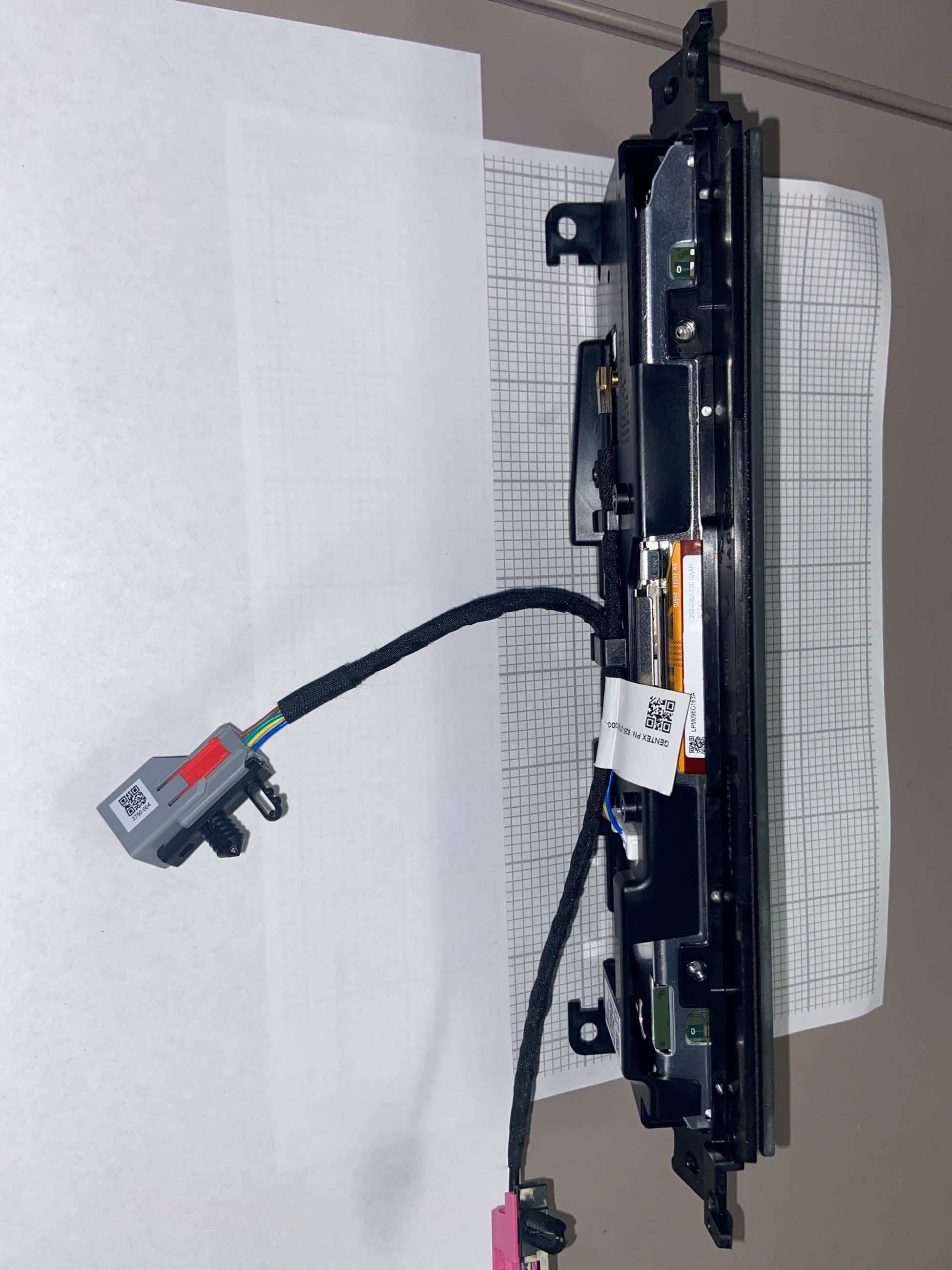
NZLRDHL6A
Jul 29, 2026Wireless Garage Door Opener
Equipment Class
CYY - Communications Receiver used w/Pt 15 Transmitter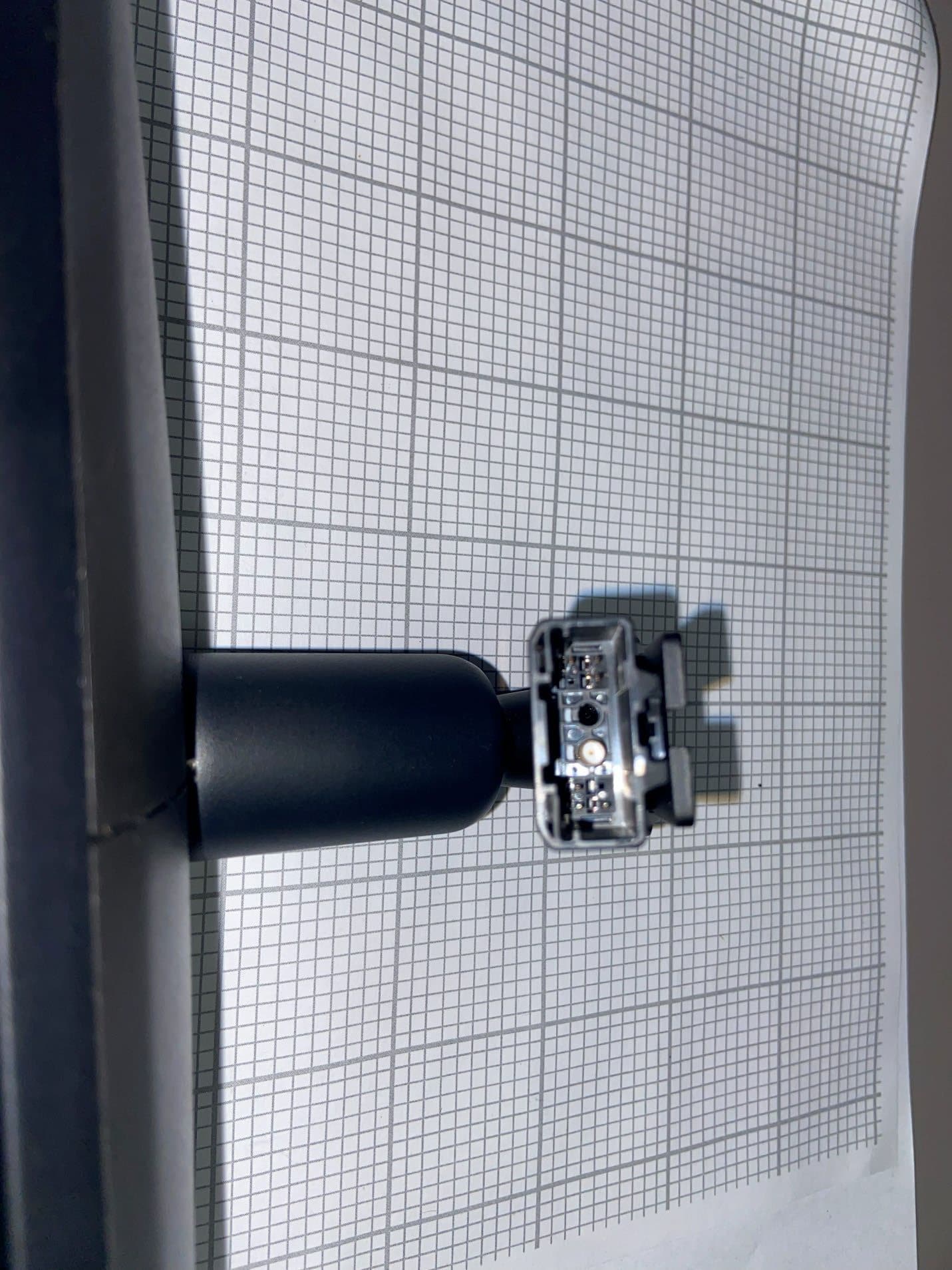
NZLFDMHL6D
Jun 15, 2026Wireless Garage Door Opener
Equipment Class
DTS - Digital Transmission System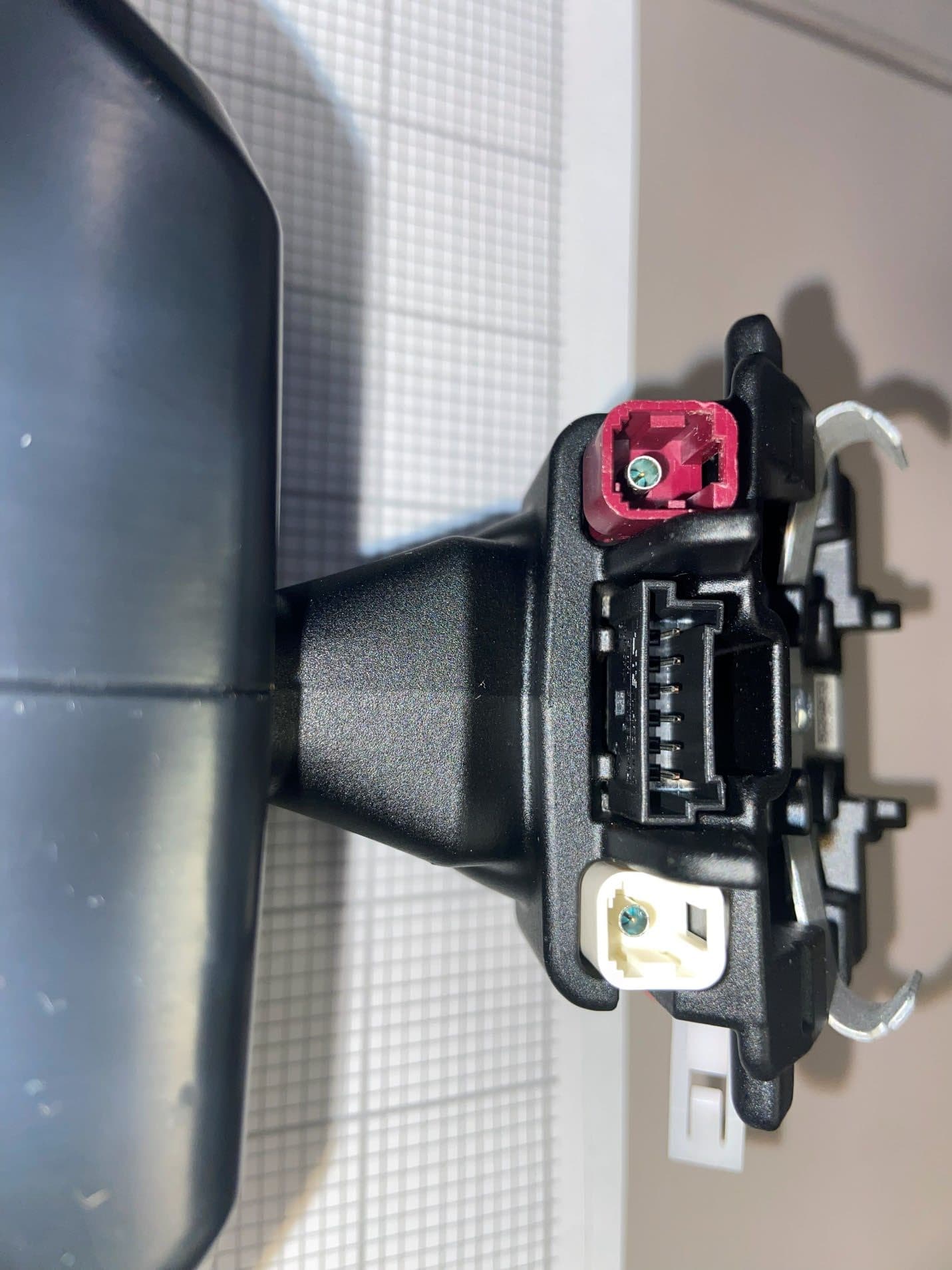
NZLFDMHL6B
May 18, 2026Wireless Garage Door Opener
Equipment Class
DSS - Part 15 Spread Spectrum Transmitter
NZLFDMHL6A
Jan 12, 2026Wireless Garage Door Opener
Equipment Class
DTS - Digital Transmission System
NZLUAHL5O
Dec 11, 2022Wireless Garage Door Opener
Equipment Class
DSC - Part 15 Security/Remote Control Transmitter