NZLFDMHL6AWireless Garage Door Opener
Gentex Corporation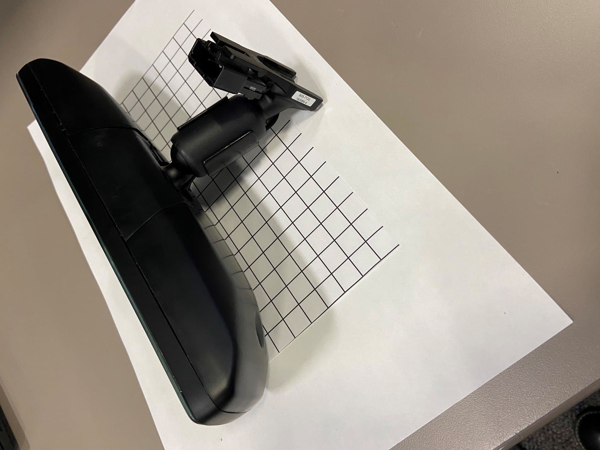
Click to zoom
Application Details
- Equipment Class
- DTS - Digital Transmission System
- Date of Grant
- Jan 12, 2026
- Application Purpose
- Original Equipment
- Equipment Note
- Wireless Garage Door Opener
- Frequency Range
- 2402.00000000 - 2480.00000000
- Company
- Gentex Corporation
- Country
- United States
Documents & Files
Document Text
Text extracted from the exhibit documents filed with the FCC. Open a document above to read the original.
Users Manual
Programming and Information Guide The following is suggested text to be included in the vehicle Owner’s Manual, to assist the End User with functionality of their HomeLink Device. Italicized text is not intended to be part of the manual text, just provided for clarification only. The HomeLink Wireless Control System provides a convenient way to replace up to three hand- held radio-frequency (RF) transmitters used to activate devices such as gate operators, garage door openers, entry door locks, security systems, even home lighting. Additional HomeLink information can be found at www.HomeLink.com , www.youtube.com/HomeLinkGentex, or by calling the toll-free HomeLink-Hotline at 1-800-355-3515 Before Programming HomeLink During programming, it is possible that garage doors, gates, or other devices may operate. For this reason, make sure that people and objects are clear of the garage door or other devices to prevent injury or other potential harm. Do not use HomeLink with any garage door opener that lacks safety stop and reverse features as required by U.S. federal safety standards (this includes any garage door opener model manufactured before April 1, 1982). A garage door that cannot detect an object - signaling the door to stop and reverse - does not meet current U.S. federal safety standards. It is recommended that a new battery be placed in the remote control transmitter for more accurate programming. Garage door opener motors manufactured after 1995 may be equipped with rolling code protection. If this is the case, you may need a stepladder or other sturdy, safe device to reach the “Learn” or “Smart” button on the garage door motor. Retain the original transmitter of the RF device you are programming for use in other vehicles as well as for future HomeLink programming. It is suggested that upon the sale or lease termination of the vehicle, the programmed HomeLink buttons be erased for security purposes. Refer to “Erasing HomeLink Buttons” later in these instructions. You can program a maximum of three devices. To change or replace any of the three devices after it has been initially programmed, you must first erase the current settings. See ‘Erasing HomeLink Buttons’ or ‘Reprogramming a Single HomeLink Button’ later in these instructions. Please note that the instructions below apply to the majority of HomeLink use cases. However, there are some HomeLink applications or HomeLink compatible systems that require slightly different instructions. HomeLink and the HomeLink house are registered trademarks of Gentex Corporation. HomeLink and the HomeLink house are registered trademarks of Gentex Corporation. Programming a New HomeLink Note: Some vehicles may require the ignition switch to be turned on or to the second (“accessories”) position for programming and/or operation of HomeLink. 1.Press the HomeLink button that you would like to program. The indicator light will flash slowly (if not, refer to “Erasing HomeLink Buttons” later in these instructions). You do not need to continue holding the HomeLink button. 2.Position the end of your hand-held transmitter 1–3 inches (2–8 cm) away from the HomeLink button while keeping the indicator light in view. Note: Some hand-held transmitters may actually train better a distance of 6-12 inches (15-20 cm). Keep this in mind if you have difficulty with the Programming Process. 3.Press and hold the hand-held transmitter button while watching the indicator light on HomeLink. Continue pressing the button until the HomeLink indicator light changes from slowly flashing to either rapidly flashing (rolling code) or continuously lit (fixed code). Now you may release the hand-held transmitter button. Note: Some devices may require you to replace this “Programming a New HomeLink” step 3 with procedures noted in the “Gate Operator / Canadian Programming” section. If the HomeLink indicator light does not change to a rapidly flashing light after performing these steps, contact HomeLink at www.HomeLink.com 4.Press the just-trained HomeLink button and observe the indicator light. •If the indicator light stays on constantly, programming is complete and your device should activate when the HomeLink button is pressed and released. •If the indicator rapidly flashes, firmly press, hold for two seconds and release the programmed HomeLink button. Repeat the "press/hold/release" sequence a second time, and, depending on the brand of the garage door opener (or other rolling code equipped device), repeat this sequence a third time to complete the programming process. At this point if your device operates, programming is complete. •If the garage door does not operate, continue with “Programming a New HomeLink” steps 5-7 to complete the programming of a rolling code equipped device. 5.At the garage door opener receiver (motor-head unit) in the garage, locate the “Learn” or “Smart” Button. This can usually be found where the hanging antenna wire is attached to the motor-head unit (see the Garage Door Opener manual to identify the “Learn Button”). Figure 1: Approximate Learn Button Location 6.Firmly press and release the “Learn” or “Smart” button. (The name and color of the button may vary by manufacturer.) There are typically 30 seconds to initiate step 7. 7.Return to the vehicle and firmly press, hold for two seconds and release the programmed HomeLink button. Repeat the “press/hold/release” sequence a second time, and, depending on the brand of the garage door opener (or other rolling code equipped device), repeat this sequence a third time to complete the programming process. HomeLink should now activate your rolling code equipped device. In the event that there are still programming difficulties or questions, additional HomeLink information and programming videos can be found online at www.HomeLink.com , youtube.com/HomeLinkGentex or by calling the HomeLink Hotline. Gate Operator / Canadian Programming Canadian radio-frequency laws require transmitter signals to “time-out” …
Text truncated - open the document above for the full version.
External Photos
FDMHL6A External Photos FDMHL6A External Photos FDMHL6A External Photos FDMHL6A External Photos FDMHL6A External Photos FDMHL6A External Photos FDMHL6A External Photos FDMHL6A External Photos
Internal Photos
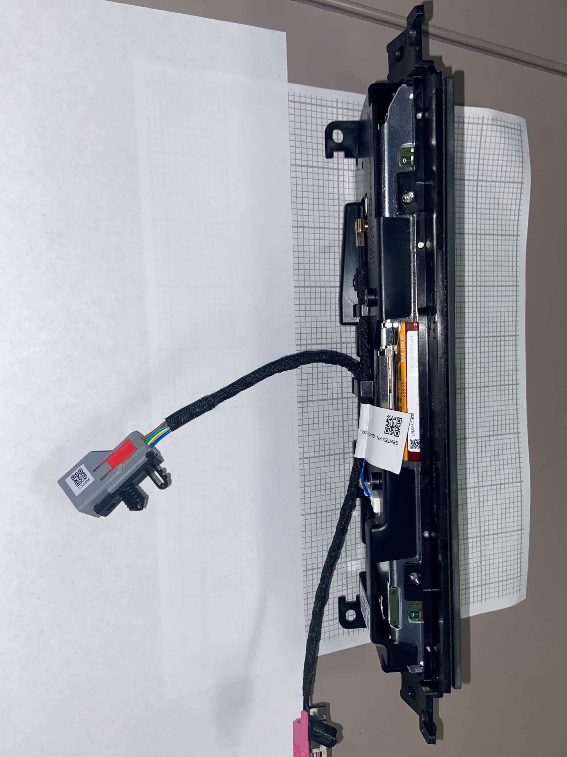
FDMHL6A Internal Photos FDMHL6A Internal Photos FDMHL6A Internal Photos FDMHL6A Internal Photos FDMHL6A Internal Photos FDMHL6A Internal Photos FDMHL6A Internal Photos FDMHL6A Internal Photos FDMHL6A Internal Photos FDMHL6A Internal Photos FDMHL6A Internal Photos FDMHL6A Internal Photos FDMHL6A Internal Photos FDMHL6A Internal Photos FDMHL6A Internal Photos FDMHL6A Internal Photos FDMHL6A Internal Photos FDMHL6A Internal Photos FDMHL6A Internal Photos FDMHL6A Internal Photos Sub GHz Tx Area FDMHL6A Internal Photos Sub GHz Trace Antenna Dimensions – Length= 62mm Width= 1mm FDMHL6A Internal Photos 2.4 GHz BLE Tx Area FDMHL6A Internal Photos 2.4 GHz BLE Trace Antenna Dimensions – Length= 20mm Width= 1mm FDMHL6A Internal Photos Top Side of PCB with shields removed
RF Exposure Info
NZLFDMHL6A FDMHL6A 3 20 Mobile 80.31 83.1 87.16 88.66 5.7 4.3 -8.28 -3.18 Antenna Gain Mobile or Portable Field Strength or Worse Case Output Power Radiated Field Strength - 288MHz(dBuV/m) Radiated Field Strength - 310MHz(dBuV/m) Radiated Field Strength - 365MHz(dBuV/m) Radiated Field Strength - 430MHz(dBuV/m) Worse Case Output Power - 902-928MHz (dBm) Worse Case Output Power - BLE - 2.4GHz (dBm) Model Information FCC ID: Model: # of Transmitters Simultaneously Transmitting Distance to User (cm) Worse Case Antenna Gain - HL High Band (dBi) Worse Case Antenna Gain - BLE (dBi) Distance to User (cm): d>20 Frequency (MHz):288 Measured Field Strength (dBuV/m): 80.31 Distance to User (cm):20 dBuV/m to V/m 0.010 Worst Case EIRP (mW)0.032220 Power Density (mW/cm 2 ) 0.000006 Power Density Limit (mW/cm 2 ) 0.2 Ratio 3.20495E-05 Model Information Requirements Exposure Condition:Mobile ExposureEvaluation Equation from page 18 of OET Bulletin 65, Edition 97-01 S=(PG)/4πR 2 Where S: power density P: power input to the antenna G: power gain of the antenna in the direction of interest relative to an isotropic radiator. R: distance to the center of radiation of the antenna Table 1 from47 CFR1.1310—Limits for Maximum Permissible Exposure (MPE) According to KDB447498 Section 3, the RF exposure guidelines adopted by the FCC are based on SAR and MPE limits. The basic restrictions for human exposure is defined by SAR limits. MPE limits are derived from the SAR limits, in terms of free-space field strength and power density. Distance to User (cm): d>20 Frequency (MHz):310 Measured Field Strength (dBuV/m): 83.10 Distance to User (cm):20 dBuV/m to V/m 0.014 Worst Case EIRP (mW)0.061252 Power Density (mW/cm 2 ) 0.000012 Power Density Limit (mW/cm 2 ) 0.206666667 Ratio 5.89632E-05 Requirements Exposure Condition:Mobile Model Information ExposureEvaluation Equation from page 18 of OET Bulletin 65, Edition 97-01 S=(PG)/4πR 2 Where S: power density P: power input to the antenna G: power gain of the antenna in the direction of interest relative to an isotropic radiator. R: distance to the center of radiation of the antenna Table 1 from47 CFR1.1310—Limits for Maximum Permissible Exposure (MPE) According to KDB447498 Section 3, the RF exposure guidelines adopted by the FCC are based on SAR and MPE limits. The basic restrictions for human exposure is defined by SAR limits. MPE limits are derived from the SAR limits, in terms of free-space field strength and power density. Distance to User (cm): d>20 Frequency (MHz):365 Measured Field Strength (dBuV/m): 87.16 Distance to User (cm):20 dBuV/m to V/m 0.023 Worst Case EIRP (mW)0.155999 Power Density (mW/cm 2 ) 0.000031 Power Density Limit (mW/cm 2 ) 0.243333333 Ratio 0.000127541 Requirements Exposure Condition:Mobile Model Information ExposureEvaluation Equation from page 18 of OET Bulletin 65, Edition 97-01 S=(PG)/4πR 2 Where S: power density P: power input to the antenna G: power gain of the antenna in the direction of interest relative to an isotropic radiator. R: distance to the center of radiation of the antenna Table 1 from47 CFR1.1310—Limits for Maximum Permissible Exposure (MPE) According to KDB447498 Section 3, the RF exposure guidelines adopted by the FCC are based on SAR and MPE limits. The basic restrictions for human exposure is defined by SAR limits. MPE limits are derived from the SAR limits, in terms of free-space field strength and power density. Distance to User (cm): d>20 Frequency (MHz):430 Measured Field Strength (dBuV/m): 88.66 Distance to User (cm):20 dBuV/m to V/m 0.027 Worst Case EIRP (mW)0.220354 Power Density (mW/cm 2 ) 0.000044 Power Density Limit (mW/cm 2 ) 0.286666667 Ratio 0.000152923 Requirements Exposure Condition:Mobile Model Information ExposureEvaluation Equation from page 18 of OET Bulletin 65, Edition 97-01 S=(PG)/4πR 2 Where S: power density P: power input to the antenna G: power gain of the antenna in the direction of interest relative to an isotropic radiator. R: distance to the center of radiation of the antenna Table 1 from47 CFR1.1310—Limits for Maximum Permissible Exposure (MPE) According to KDB447498 Section 3, the RF exposure guidelines adopted by the FCC are based on SAR and MPE limits. The basic restrictions for human exposure is defined by SAR limits. MPE limits are derived from the SAR limits, in terms of free-space field strength and power density. Distance to User (cm): d> 20 Frequency (MHz):902 Distance to User (cm):20 Worse Case Output Power (dBm): 5.70 Distance to User (cm):20.1 Antenna Gain (dBi)-8.28 Numerical Antenna Gain0.148593564 Tune Up Adjustment (dB)1 Worse Case Output Power with tune up tolerance (dBm): 6.70 Worse Case Output Power with tune up tolerance (mW): 4.677 EIRP (mW)0.695024 Power Density (mW/cm 2 ) 0.000931 Power Density Limit (mW/cm 2 ) 0.601333333 Ratio 0.001548229 Requirements Exposure Condition:Mobile Model Information ExposureEvaluation Equation from page 18 of OET Bulletin 65, Edition 97-01 S=(PG)/4πR 2 Where S: power density P: power input to the antenna G: power gain of the antenna in the direction of interest relative to an isotropic radiator. R: distance to the center of radiation of the antenna Table 1 from47 CFR1.1310—Limits for Maximum Permissible Exposure (MPE) According to KDB447498 Section 3, the RF exposure guidelines adopted by the FCC are based on SAR and MPE limits. The basic restrictions for human exposure is defined by SAR limits. MPE limits are derived from the SAR limits, in terms of free-space field strength and power density. Distance to User (cm): d> 20 Frequency (MHz):2402 Distance to User (cm):20 Worse Case Output Power (dBm): 4.30 Distance to User (cm):20 Antenna Gain (dBi)-3.18 Numerical Antenna Gain0.480839348 Tune Up Adjustment (dB)1 Worse Case Output Power with tune up tolerance (dBm): 5.30 Worse Case Output Power with tune up tolerance (mW): 3.388 EIRP (mW)1.629296 Power Density (mW/cm 2 ) 0.000674 Power Density Limit (mW/cm 2 ) 1 Ratio 0.000674451 Requirements Expo…
Text truncated - open the document above for the full version.
Test Report
600 N. Centennial Street, Zeeland, MI 49464 Electrical Engineering Department Antenna Information Template Rev 001 (2022‐11) Page 1 of 11 Gentex Confidential Information WLAN ANTENNA INFORMATION ODM Antenna Manufacturer Gentex Corporation Address 600 N. Centennial, Zeeland, MI 49464 FCC Model Antenna Type Monopole and Inverted F ODM Test Personnel Christian Ro and Denise Shaw Test Date 11/26/2025 Test Location 600 N. Centennial, Zeeland, MI 49464 USA Performance Specifications Antenna Peak Gain w/ Cable Loss (dBi) Frequency 902.25 MHz 914.75 MHz 926.75 MHz 2402 MHz 2440 MHz 2480 MHz Ex: Monopole Antenna ‐8.28 ‐8.42 ‐8.87 Ex: Inverted F Antenna ‐3.18 ‐4.31 ‐4.87 For the 15.231 bands, only radiated measurements are used to show compliance with the FCC limits for fundamental and spurious emissions. Revision Notes / Changes Test Personnel/ Author Reviewer Approver Date AAA Initial approved release Denise Shaw Christian Ro Doug Papay 12/10/2025 600 N. Centennial Street, Zeeland, MI 49464 Electrical Engineering Department Antenna Information Template Rev 001 (2022‐11) Page 2 of 11 Gentex Confidential Information CONTENTS WLAN Antenna Information ........................................................................................................................................................ 1 Contents....................................................................................................................................................................................... 2 1 Test Setup ............................................................................................................................................................................ 3 1.1 Test Methodology ......................................................................................................................................................... 3 1.2 Test Setup diagram ........................................................................................................................................................ 3 1.3 Equipment Description .................................................................................................................................................. 4 2 Antenna Information ........................................................................................................................................................... 5 600 N. Centennial Street, Zeeland, MI 49464 Electrical Engineering Department Antenna Information Template Rev 001 (2022‐11) Page 3 of 11 Gentex Confidential Information 1 TEST SETUP 1.1 TEST METHODOLOGY The radiation pattern of the Antenna Under Test is measured in both horizontal and vertical polarization. These measurements are performed in an anechoic chamber using cross polarized Vivaldi Antennas mounted to a boom. The AMS32 software controls the equipment and records the measurements. The data is translated to a 3D image for each frequency tested. 1.2 TEST SETUP DIAGRAM 600 N. Centennial Street, Zeeland, MI 49464 Electrical Engineering Department Antenna Information Template Rev 001 (2022‐11) Page 4 of 11 Gentex Confidential Information 1.3 EQUIPMENT DESCRIPTION Device Model Serial # Manufacturer Last Cal Date Cal Due Date Radio communication tester CMW 270 1201.0002K75‐ 102483‐zQ Rohde & Schwarz 11/22/2023 11/22/2025 Network analyzer ZNB 8 1311.6010K44‐ 104394‐nz Rohde & Schwarz 2/17/2023 2/17/2026 Open Switch and Control Unit OSP230 1528.3105K03‐ 101719‐GF Rohde & Schwarz VBU VBU Position Controller for the WPTC NCD 557/3222.01 Maturo VBU VBU Anechoic chamber TC‐OTAXS N/A Rohde & Schwarz 4/7/2025 4/7/2026 Cross Polarized Vivaldi Antenna DST‐B215 N/A Rohde & Schwarz VBU VBU Broadband Link Antenna TS‐F24‐V2 N/A Rohde & Schwarz VBU VBU Cable Set TS8991‐CAB N/A Rohde & Schwartz 4/7/2025 4/7/2026 Over‐the‐Air performance Software AMS32 N/A Rohde & Schwartz VBU VBU 600 N. Centennial Street, Zeeland, MI 49464 Electrical Engineering Department Antenna Information Template Rev 001 (2022‐11) Page 5 of 11 Gentex Confidential Information 2 ANTENNA INFORMATION Antenna Pattern 902.25 MHz Peak Realized Gain: ‐8.28 dBi 600 N. Centennial Street, Zeeland, MI 49464 Electrical Engineering Department Antenna Information Template Rev 001 (2022‐11) Page 6 of 11 Gentex Confidential Information Antenna Pattern 914.75 MHz Peak Realized Gain: ‐8.42 dBi 600 N. Centennial Street, Zeeland, MI 49464 Electrical Engineering Department Antenna Information Template Rev 001 (2022‐11) Page 7 of 11 Gentex Confidential Information Antenna Pattern 926.75 MHz Peak Realized Gain: ‐8.87 dBi 600 N. Centennial Street, Zeeland, MI 49464 Electrical Engineering Department Antenna Information Template Rev 001 (2022‐11) Page 8 of 11 Gentex Confidential Information Antenna Pattern 2402 MHz Peak Realized Gain: ‐3.18 dBi 600 N. Centennial Street, Zeeland, MI 49464 Electrical Engineering Department Antenna Information Template Rev 001 (2022‐11) Page 9 of 11 Gentex Confidential Information Antenna Pattern 2440 MHz Peak Realized Gain: ‐4.31 dBi 600 N. Centennial Street, Zeeland, MI 49464 Electrical Engineering Department Antenna Information Template Rev 001 (2022‐11) Page 10 of 11 Gentex Confidential Information Antenna Pattern 2480 MHz Peak Realized Gain: ‐4.87 dBi 600 N. Centennial Street, Zeeland, MI 49464 Electrical Engineering Department Antenna Information Template Rev 001 (2022‐11) Page 11 of 11 Gentex Confidential Information APPENDIX SETUP PHOTOS Z X Y
Test Report
Lab Project ID#: EMC2025-15019 Test ID: Test-128197, 128200 Model: FDMHL6A FCC Report Form for 15.247 Bluetooth LE – 3m Date: 12/8/2025 Revision: 11/14/2025 Approved By: Jason Vargo Page 1 of 36 Uncontrolled copy if printed unless stamped as a Lab Controlled Document Technical Report to the FCC and ISED Regarding Gentex Corporation - Homelink© VI Model: FDMHL6A FCC ID: NZLFDMHL6A ISED: 4112A-FDMHL6A Emission Designator: 1M055L1D 12/8/2025 A report concerning approval for Gentex Corporation Homelink® model FDMHL6A Please issue grant immediately upon review. Measurements Made by: Bolay Pacheco Laboratory Validation Engineer III Gentex Corporation Report Prepared Measurements Reviewed by: Patricia Szeszulski Michael Foster Laboratory Validation Engineer I Laboratory Regulatory Engineer I Gentex Corporation Gentex Corporation Report Submitted by: Report Approved by: Brian Miller Jason Vargo Laboratory Group Leader – Regulatory II Laboratory Manager I Gentex Corporation Gentex Corporation Lab Project ID#: EMC2025-15019 Test ID: Test-128197, 128200 Model: FDMHL6A FCC Report Form for 15.247 Bluetooth LE – 3m Date: 12/8/2025 Revision: 11/14/2025 Approved By: Jason Vargo Page 2 of 36 Uncontrolled copy if printed unless stamped as a Lab Controlled Document Test Report Revision REV Number Date Author Description 1.0 12/8/2025 Patricia Szeszulski Initial Release Results relate only to the items tested as received. Compliance has been evaluated based on the Lab Manual section 7.6.2. The decision rule used regarding measurement uncertainty was to determine results solely on whether the measured values met the defined acceptance criteria without factoring in measurement uncertainty values. Lab Project ID#: EMC2025-15019 Test ID: Test-128197, 128200 Model: FDMHL6A FCC Report Form for 15.247 Bluetooth LE – 3m Date: 12/8/2025 Revision: 11/14/2025 Approved By: Jason Vargo Page 3 of 36 Uncontrolled copy if printed unless stamped as a Lab Controlled Document 1. General Information 1.1. Product Description The Gentex Corporation HomeLink® HLVI Universal Garage Door Opener is a low-power transceiver OEM device that is installed into the automotive rearview mirror. The installation is provided by trained technicians during the course of the manufacture of the automobile. It is powered by the 12 Volt system of the automobile. This Universal Garage Door Opener has the capability to 1. Learn the frequency and bit code format of the user’s existing garage door remote control devices 2. Transmit and receive frequency hopping spread spectrum in the 902 to 928 MHz band using an internal antenna as per Federal Communications Commission “Code of Federal Regulations”, Title 47, Part 15.247 3. Transmit and receive frequency digital transmission system in the 2402 to 2480MHz band using an internal antenna as per Federal Communications Commission “Code of Federal Regulations”, Title 47, Part 15.247. The unit is designed for the periodic operation of a control signal, which typically activates a garage door opener receiver. The unit is supplied to the automobile manufacturer without harness. For testing purposes, a typical assembly and 2-conductor cable harness were used to power to the unit. The three-button HomeLink® unit replaces up to three hand-held transmitters. In addition to the typical operation of the garage door, the unit will learn the radio frequency codes of other transmitter types to activate entry door locks, estate gates, security systems, and home or office lighting. The antenna system is an integral part of the unit. It cannot be altered nor replaced by the user. The service of this system is only available from the Automobile Manufacturer’s Dealerships and Gentex Corporation. 1.2. Related Grants This device will have functionality that is covered under 47 CFR 15.247, 15.231, and 15B and ISED RSS-247, and 210. The device will have an FCC ID # of NZLFDMHL6A and an ISED ID # of 4112A-FDMHL6A under both rule parts. Separate reports were submitted for functionality covered under other rule parts. 1.3. Test Methodology Radiated Emissions testing was performed according to ANSI C63.10:2020+Cor.1-2023 and ANSI C63.10a:2024. The power source for this product is a 12V automotive vehicle battery. Conducted measurements were performed using a power supply. Measurements were performed per FCC OET KDB 558074. The unit is supplied to the automobile manufacturer without harness. For testing purposes, a 2-conductor cable harness was used to interface to the unit. The unit ground is provided through the negative terminal of the harness. Lab Project ID#: EMC2025-15019 Test ID: Test-128197, 128200 Model: FDMHL6A FCC Report Form for 15.247 Bluetooth LE – 3m Date: 12/8/2025 Revision: 11/14/2025 Approved By: Jason Vargo Page 4 of 36 Uncontrolled copy if printed unless stamped as a Lab Controlled Document 1.4. Test Facility The 3-meter semi-anechoic chamber where these measurements were taken, is located on the grounds of Gentex Corporation’s Corporate Labs, in the city of Zeeland, county of Ottawa, state of Michigan, United States of America. For radiated measurements above 1 GHz, RF absorbing material is placed between the antenna and EUT in accordance with ANSI C63.10:2020+Cor.1-2023 and ANSI C63.10a:2024 Section 5.5 and chamber manufacturer’s instructions. The 3m chamber has been added to our A2LA scope of accreditation on 05/20/2016 and includes accreditation to ANSI C63.4:2014, ANSI C63.10:2020+Cor.1-2023 and ANSI C63.10a:2024. The report filed with ISED, dated February 11, 2015, was accepted via a letter dated February 11, 2015. Our 3m chamber is registered with the ISED under Site# 4112A-2 and FCC under registration number 357351. Corporate Mailing/Shipping Address Gentex Corporation 600 N. Centennial Street Zeeland, MI 49464 Site Address Gentex Corporation 380 Riley Street Zeeland, MI 49423 1.5. Accreditation The Gentex Corporate EMC Lab is accredited to ISO/IEC 17025 by the American Association for Laboratory Accredita…
Text truncated - open the document above for the full version.
Test Setup Photos
Test Setup Photos Part 15.231 and 15.247 DUT Vehicle Orientation LPA (200-1000MHz) Setup Overview DRWG Horn (1-18GHz) Setup Overview DRWG Horn (18-26GHz) Setup Overview Conducted Setup Bicon (30-200MHz) Setup Overview
Contact Information
Applicant
Brian Miller(Corporate Labs Group Leader - Wireless Regulatory)
[email protected]Fax: 616-748-8174
Technical Contact
Gentex CorporationDave Newhouse
600 N. Centennial Street · Zeeland, Michigan, 49464 · United States
Test Firm
Gentex CorporationBrian Miller
[email protected]Fax: 6167727348
Technical Specifications
| # | Rule Parts | Frequency Range | Power Output |
|---|---|---|---|
| 1 | 15C | 2.40 GHz - 2.48 GHz | 3.00 mW |
Other Applications from Gentex Corporation
NZLRDHL6A
Jul 29, 2026Wireless Garage Door Opener
Equipment Class
CYY - Communications Receiver used w/Pt 15 Transmitter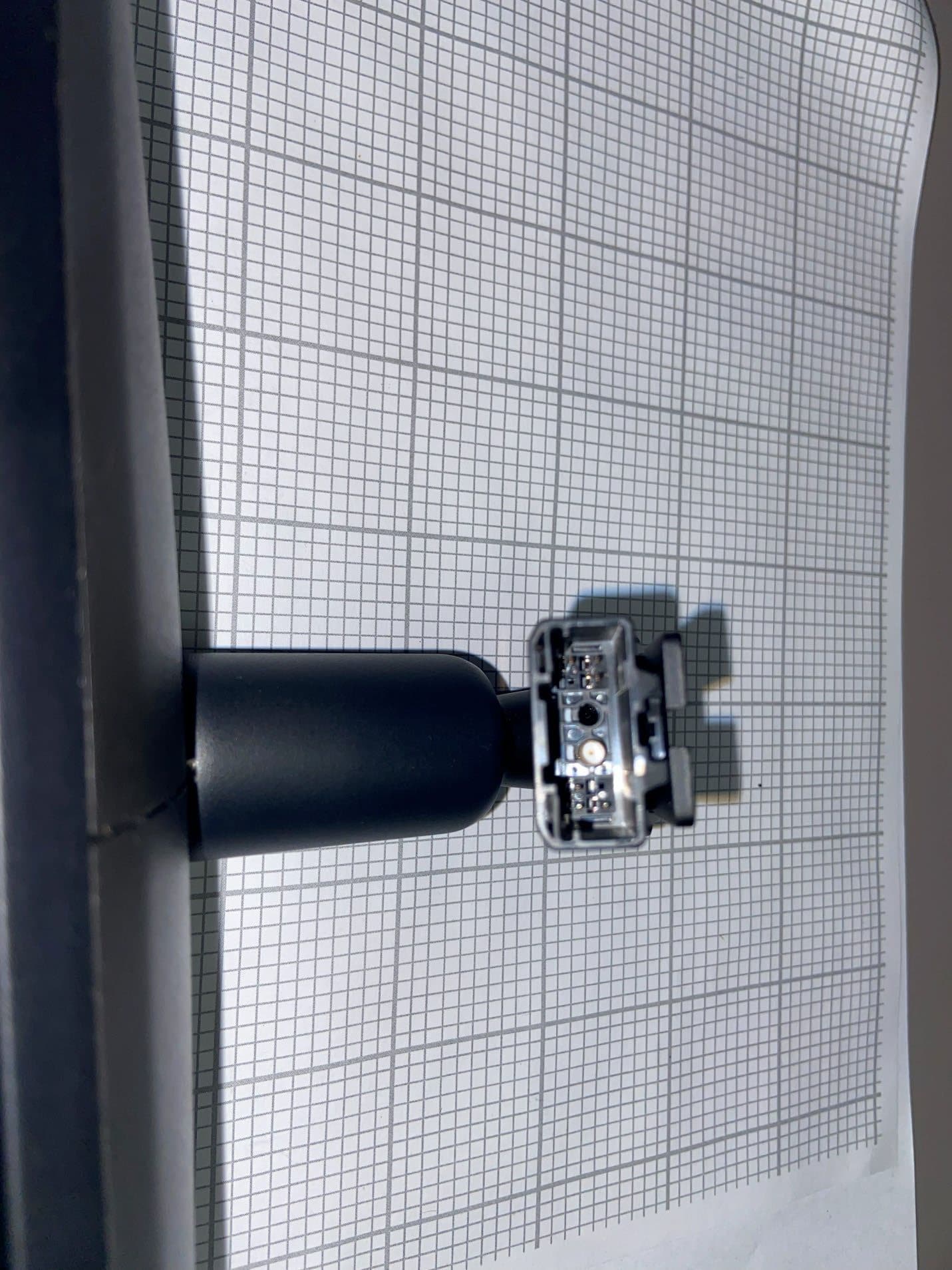
NZLFDMHL6D
Jun 15, 2026Wireless Garage Door Opener
Equipment Class
DTS - Digital Transmission System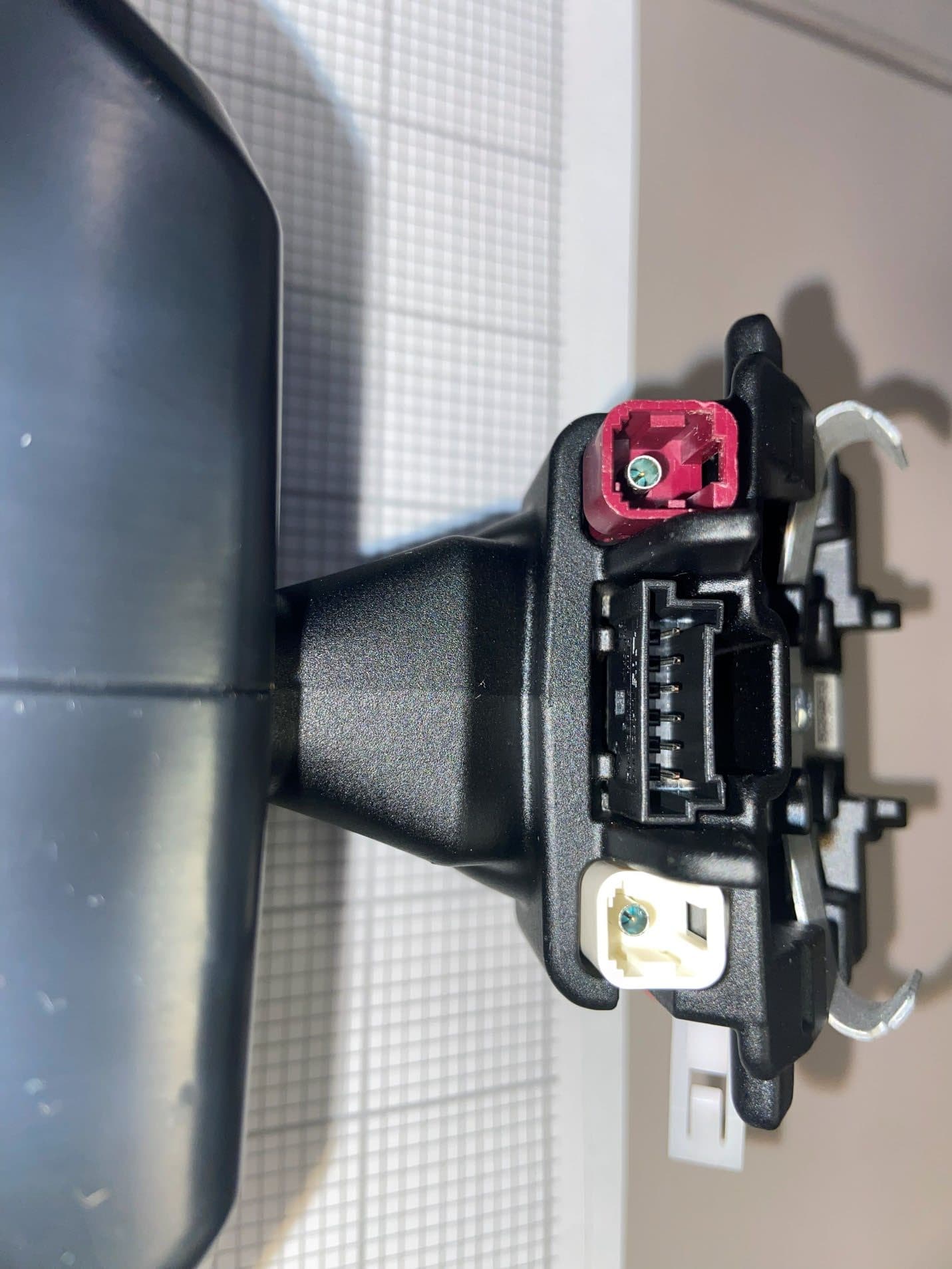
NZLFDMHL6B
May 18, 2026Wireless Garage Door Opener
Equipment Class
DSS - Part 15 Spread Spectrum Transmitter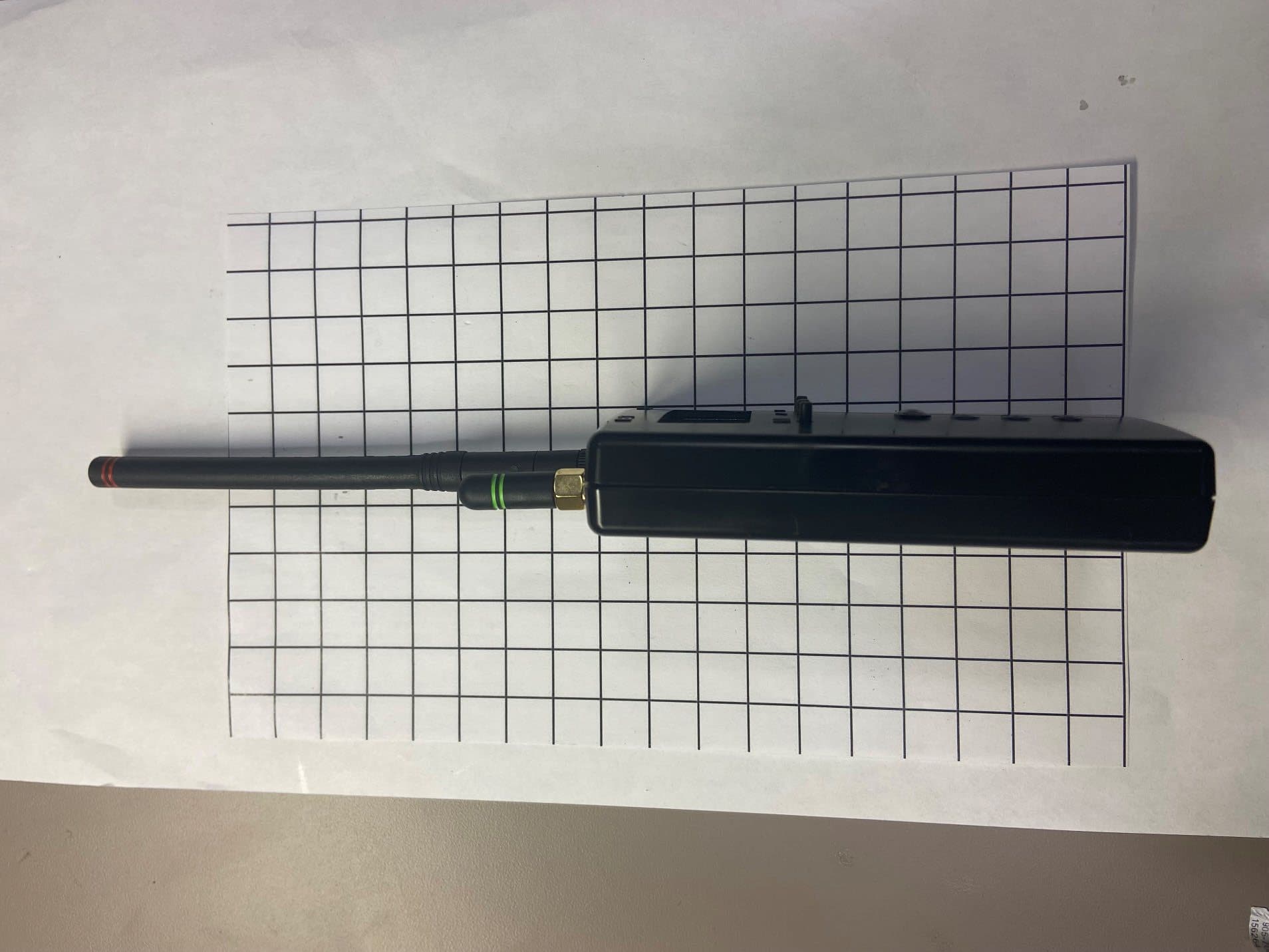
NZLDEFRX6
May 04, 2026Default Receiver
Equipment Class
DTS - Digital Transmission System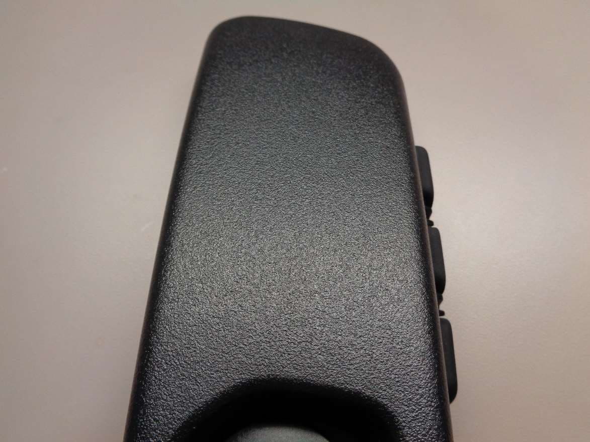
NZLUAHL5O
Dec 11, 2022Wireless Garage Door Opener
Equipment Class
DSC - Part 15 Security/Remote Control Transmitter