NZLJLXHL4HomeLink TX
Gentex Corporation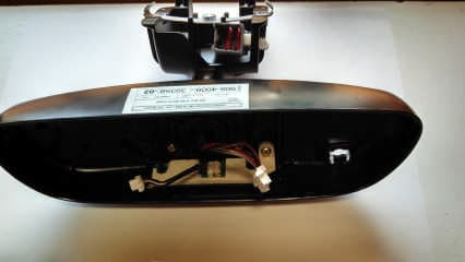
Click to zoom
Application Details
- Equipment Class
- DSR - Part 15 Remote Control/Security Device Transceiver
- Date of Grant
- Nov 26, 2013
- Application Purpose
- Original Equipment
- Date of Application
- Nov 26, 2013
- Equipment Note
- HomeLink TX
- Frequency Range
- 411.00000000 - 452.00000000
- Company
- Gentex Corporation
- Country
- United States
Documents & Files
Document Text
Text extracted from the exhibit documents filed with the FCC. Open a document above to read the original.
Users Manual
Programming and Information Guide The HomeLink Wireless Control System provides a convenient way to replace up to three hand- held radio-frequency (RF) transmitters used to activate devices such as gate operators, garage door openers, entry door locks, security systems, even home lighting. Additional HomeLink information can be found on the Internet at www.homelink.com . Precautions ! Before programming HomeLink to a garage door opener or gate operator, make sure that people and objects are out of the way of the device to prevent potential harm or damage. When programming a garage door opener, it is advised to park outside of the garage. Do not use HomeLink with any garage door opener that lacks safety stop and reverse features as required by U.S. federal safety standards (this includes any garage door opener model manufactured before April 1, 1982). A garage door that cannot detect an object - signaling the door to stop and reverse - does not meet current U.S. federal safety standards. For more information, contact HomeLink at: www.homelink.com . Certain garage door drives are incompatible with HomeLink Wireless Control System. If you have any difficulty programming, please contact the HomeLink® Hotline Assistance Center at 1- 800-355-3515. Retain the original transmitter of the RF device you are programming for use in other vehicles as well as for future HomeLink programming. It is also suggested that upon the sale of the vehicle, the programmed HomeLink buttons be erased for security purposes. Refer to “Erasing HomeLink Buttons”. Programming HomeLink Note: Some vehicles may require the ignition switch to be turned on or to the second (“accessories”) position for programming and/or operation of HomeLink. It is also recommended that a new battery be placed in the hand-held transmitter of the device being programmed to HomeLink for quicker training and accurate transmission of the radio-frequency signal. 1. Position the end of your hand-held transmitter 1–3 inches (5–14 cm) away from the HomeLink button you wish to program while keeping the indicator light in view. 2. Simultaneously press and hold both the chosen HomeLink and hand-held transmitter buttons until the HomeLink indicator light changes from a slow to a rapidly blinking light. Now you may release both the HomeLink and hand-held transmitter buttons. Note: Some devices may require you to replace this Programming Step 2 with procedures noted in the “Gate Operator / Canadian Programming” section. If the HomeLink indicator light does not change to a rapidly blinking light after performing these steps, contact HomeLink at www.homelink.com. 3. Firmly press, hold for five seconds and release the programmed HomeLink button up to two separate times to activate the door. If the door does not activate, press and hold the just- trained HomeLink button and observe the indicator light. • If the indicator light stays on constantly, programming is complete and your device should activate when the HomeLink button is pressed and released. • If the indicator light blinks rapidly for two seconds and then turns to a constant light continue with “Programming” steps 4-6 to complete the programming of a rolling code equipped device (most commonly a garage door opener). 4. At the garage door opener receiver (motor-head unit) in the garage, locate the “learn” or “smart” button. This can usually be found where the hanging antenna wire is attached to the motor-head unit. 5. Firmly press and release the “learn” or “smart” button. (The name and color of the button may vary by manufacturer.) There are 30 seconds to initiate step 6. 6. Return to the vehicle and firmly press, hold for two seconds and release the programmed HomeLink button. Repeat the “press/hold/release” sequence a second time, and, depending on the brand of the garage door opener (or other rolling code equipped device), repeat this sequence a third time to complete the programming process. HomeLink should now activate your rolling code equipped device. Gate Operator / Canadian Programming Canadian radio-frequency laws require transmitter signals to “time-out” (or quit) after several seconds of transmission – which may not be long enough for HomeLink to pick up the signal during programming. Similar to this Canadian law, some U.S. gate operators are designed to “time-out” in the same manner. If you live in Canada or you are having difficulties programming a gate operator or garage door opener by using the “Programming” procedures, replace “Programming HomeLink” step 2 with the following: Note: If programming a garage door opener or gate operator, it is advised to unplug the device during the “cycling” process to prevent possible overheating. 2. Continue to press and hold the HomeLink button while you press and release - every two seconds (“cycle”) your hand-held transmitter until the HomeLink indicator light changes from a slow to a rapidly blinking light. Now you may release both the HomeLink and hand-held transmitter buttons. Proceed with “Programming” step 3 to complete. Using HomeLink To operate, simply press and release the programmed HomeLink button. Activation will now occur for the trained device (i.e. garage door opener, gate operator, security system, entry door lock, home/office lighting, etc.). For convenience, the hand-held transmitter of the device may also be used at any time. In the event that there are still programming difficulties or questions, contact HomeLink at: www.homelink.com. Erasing HomeLink Buttons To erase programming from the three buttons (individual buttons cannot be erased but can be “reprogrammed” as outlined below), follow the step noted: • Press and hold the two outer HomeLink buttons until the indicator light begins to flash-after 10 seconds. Release both buttons. Do not hold for longer that 20 seconds. HomeLink is now in the train (or learning) mode and can be programmed at any time beginning with “Programming” - step 1. Reprogramming a Single HomeLink But…
Text truncated - open the document above for the full version.
External Photos
Exterior Mirror View Front Exterior View Mirror Assy Front Exterior View Rear
Internal Photos
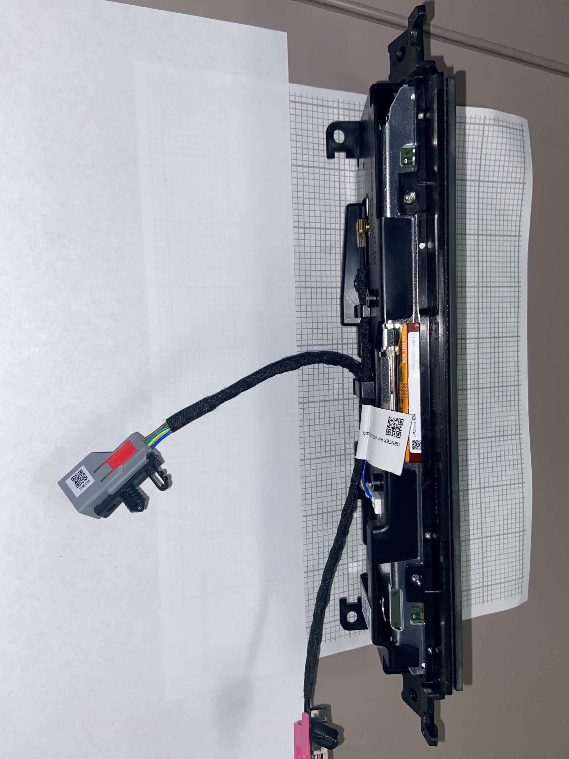
JLX Homelink PCB Top View JLX Homelink PCB Bottom View Homelink PCB Bottom Cover
Test Report
Amber Helm Development L.C. 92723 Michigan Hwy-152 Sister Lakes, MI 49047 A copy of this Report will be on file with AHD to:November, 2023Page1 of 40 EMC Test Report #1301752FX-JLXHL4 Issued11/27/13 Regarding the FCC Part 15 testing Rear View Mirror Model Number:JLXHL4 Family Category:15.231 Transmitting Device FCC ID NZLJLXHL4 Judgments:FCC Part 15.231 – Compliant NVLAP LAB CODE 200129-0 Prepared for:Craig Harder Gentex Corp. 600 N Centenial St Zeeland, Mi. 49464 Test Date(s):08/8/13-11/14/13 Report prepared by:Report reviewed by David J. Miller, NCEGordon L. Helm, NCE Data recorded by:_________________________ Gordon L. Helm, NCE Test Engineer, AHD Test report #1301752FX-JLXHL4Tested date: 8/8/13-11/14/13 FCC 15.231 Testing for JLXHL4 Auto Mirror Assy Family AHD EMC Lab, 92723 Michigan Hwy-152, Sister Lakes, MI 49047 (269) 429-8352 Page 2 of 40 Table of Contents Statements concerning this report ................................................................................................... 3 FCC Required user statements: .............................................................................................................. 4 FCC Part 15 Class A or B Digital Devices or Peripherals: .................................................................... 4 Industry Canada Required user statements: ........................................................................................... 5 Summary of Results ........................................................................................................................ 7 Changes Made to Achieve Compliance: ................................................................................................ 8 EUT Descriptions ............................................................................................................................ 9 Specifications: ...................................................................................................................................... 10 EUT Block Diagram:............................................................................................................................ 10 EUT Pictures ........................................................................................................................................ 11 Equipment Test Setup: .................................................................................................................. 15 Support Equipment & Cabling ............................................................................................................. 15 Setup Pictures ....................................................................................................................................... 16 Measurement Report ..................................................................................................................... 18 Standards Applied to Test .................................................................................................................... 18 Equipment Configuration ..................................................................................................................... 18 Test Methodology................................................................................................................................. 18 Transmit: .............................................................................................................................................. 18 Receive: ................................................................................................................................................ 19 Radiated:............................................................................................................................................... 19 Variance from Test Procedure:............................................................................................................. 19 Test Data............................................................................................................................................... 20 Restricted Band Harmonic Peak Compliance ...................................................................................... 24 Transmit Mode Non-Harmonic Spurious Emissions ........................................................................... 24 Receive Mode Manufacturing Test Burst ............................................................................................ 24 Receive Spurious Measurements.......................................................................................................... 25 Device Deactivation ............................................................................................................................. 26 Band Edge and Restricted Band Testing .............................................................................................. 27 Band Edge Testing Results Table ........................................................................................................ 27 Duty Cycle............................................................................................................................................ 28 20 dB Bandwidth Measurement: .......................................................................................................... 30 Training Pulse Measurement................................................................................................................ 32 Environment ......................................................................................................................................... 33 APPENDIX A ............................................................................................................................... 34 Measurement Procedures ..................................................................................................................... 34 Line Conducted .................................................................................…
Text truncated - open the document above for the full version.
Test Setup Photos
Radiated Prescreen Setup Front Orientation Transmit End Orientation Transmit Side Orientation Transmit
Contact Information
Applicant
Brian Miller(Corporate Labs Group Leader - Wireless Regulatory)
Test Firm
AHD EMC LaboratoryGordon Helm
Technical Specifications
| # | Rule Parts | Frequency Range | Power Output |
|---|---|---|---|
| 3 | 15.231 | 411 MHz - 452 MHz | - |
Other Applications from Gentex Corporation
NZLRDHL6A
Jul 29, 2026Wireless Garage Door Opener
Equipment Class
CYY - Communications Receiver used w/Pt 15 Transmitter
NZLFDMHL6D
Jun 15, 2026Wireless Garage Door Opener
Equipment Class
DTS - Digital Transmission System
NZLFDMHL6B
May 18, 2026Wireless Garage Door Opener
Equipment Class
DSS - Part 15 Spread Spectrum Transmitter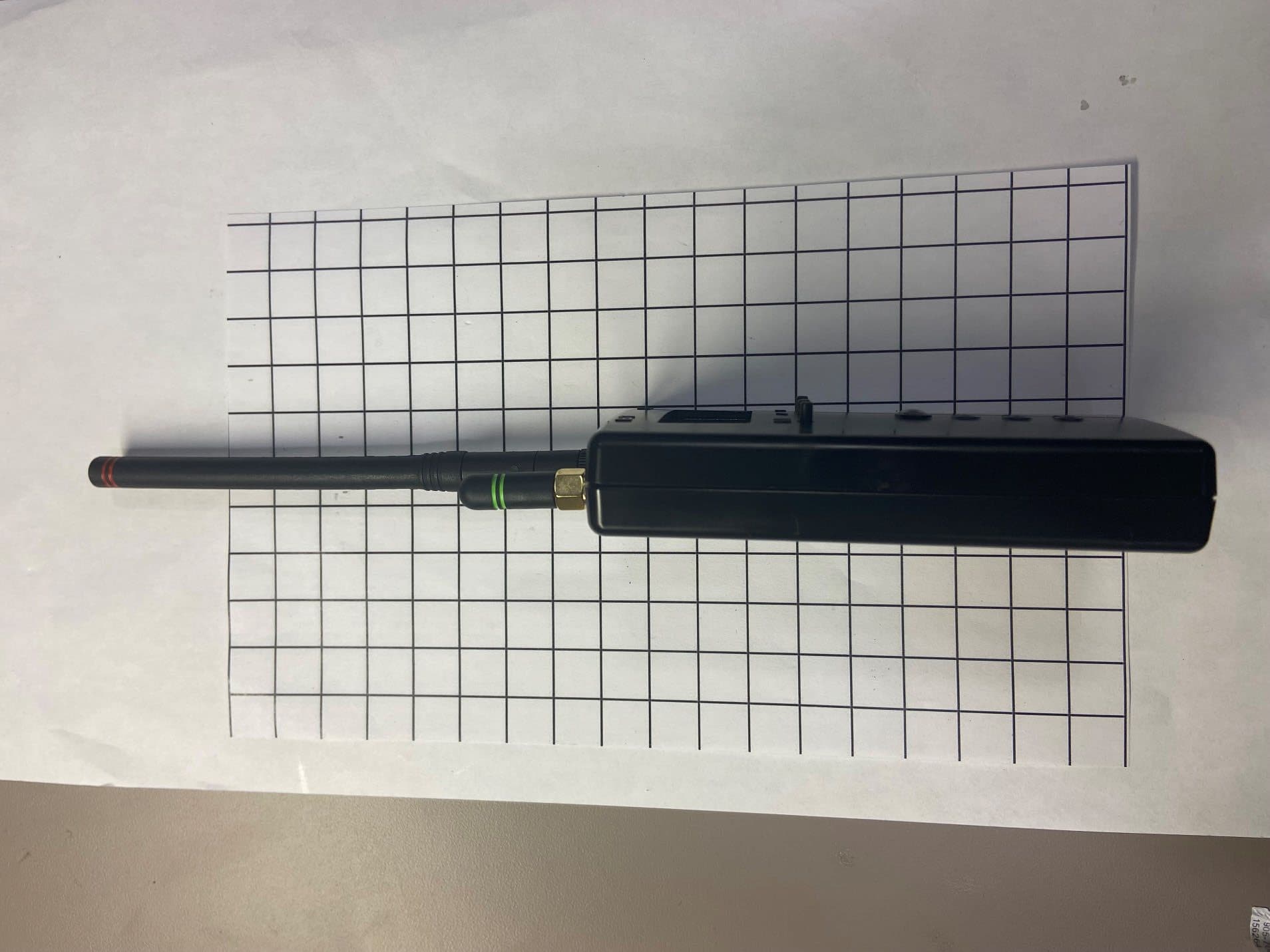
NZLDEFRX6
May 04, 2026Default Receiver
Equipment Class
DTS - Digital Transmission System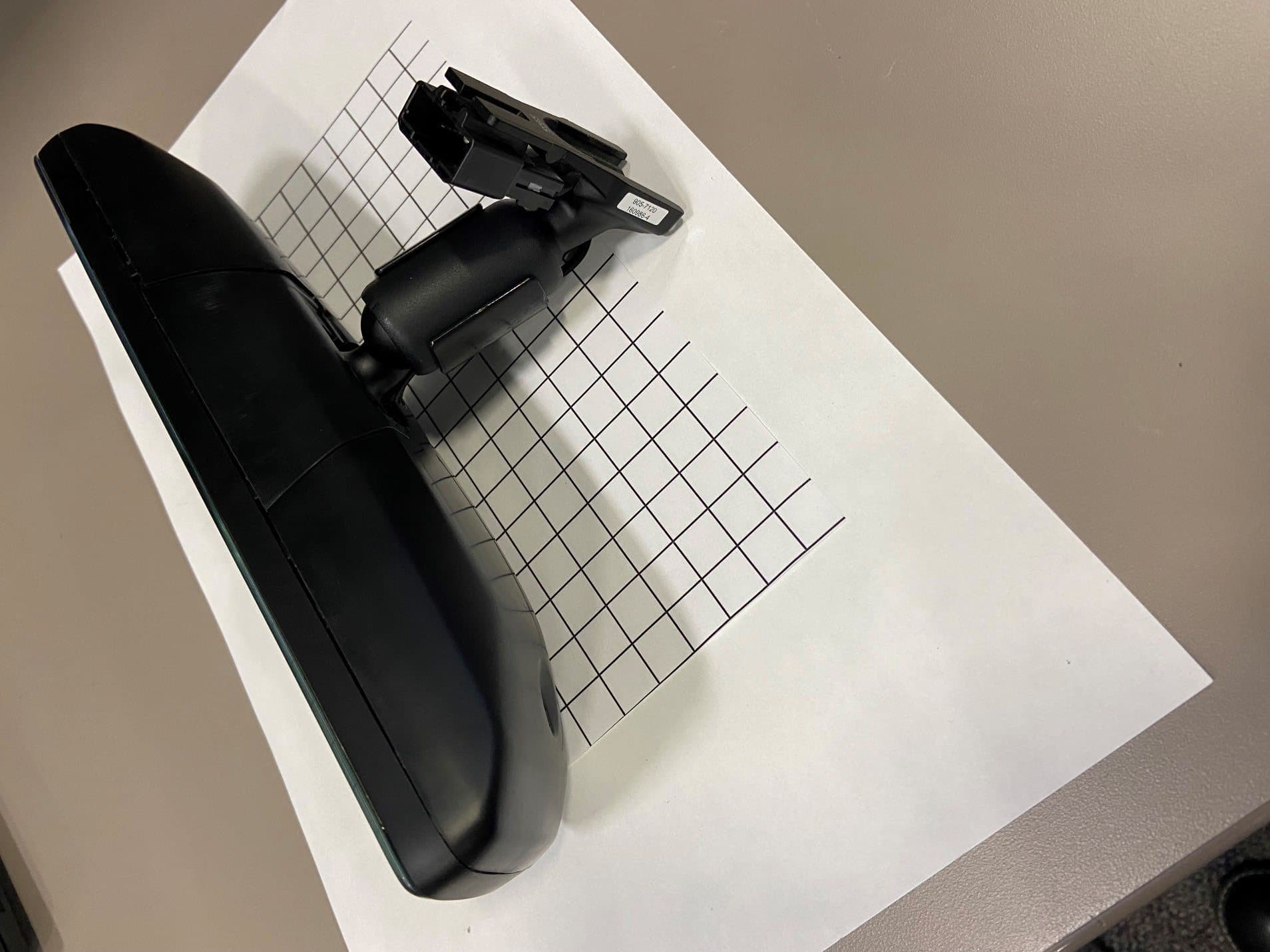
NZLFDMHL6A
Jan 12, 2026Wireless Garage Door Opener
Equipment Class
DTS - Digital Transmission System