NZLLCTHL3Universal Garage Door Opener in Mirror
Gentex Corporation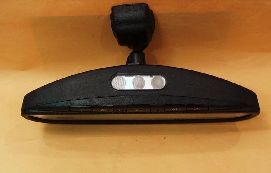
Click to zoom
Application Details
- Equipment Class
- DSC - Part 15 Security/Remote Control Transmitter
- Date of Grant
- Apr 25, 2002
- Application Purpose
- Original Equipment
- Date of Application
- Apr 25, 2002
- Equipment Note
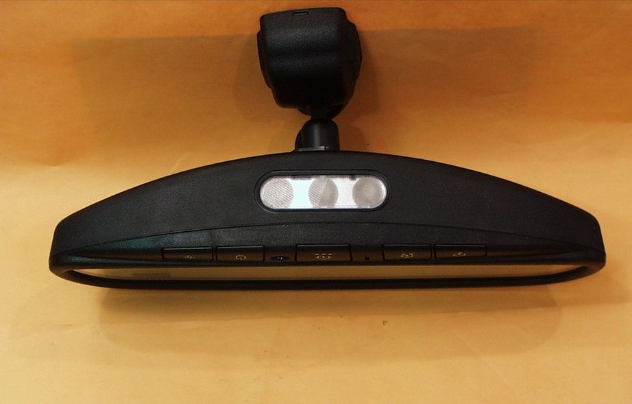
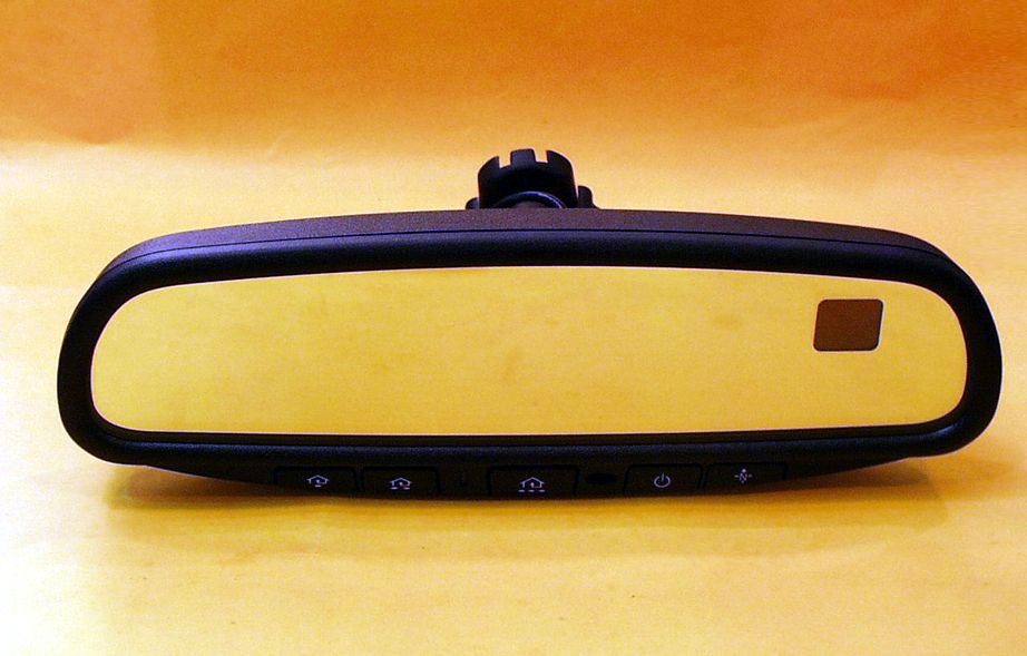
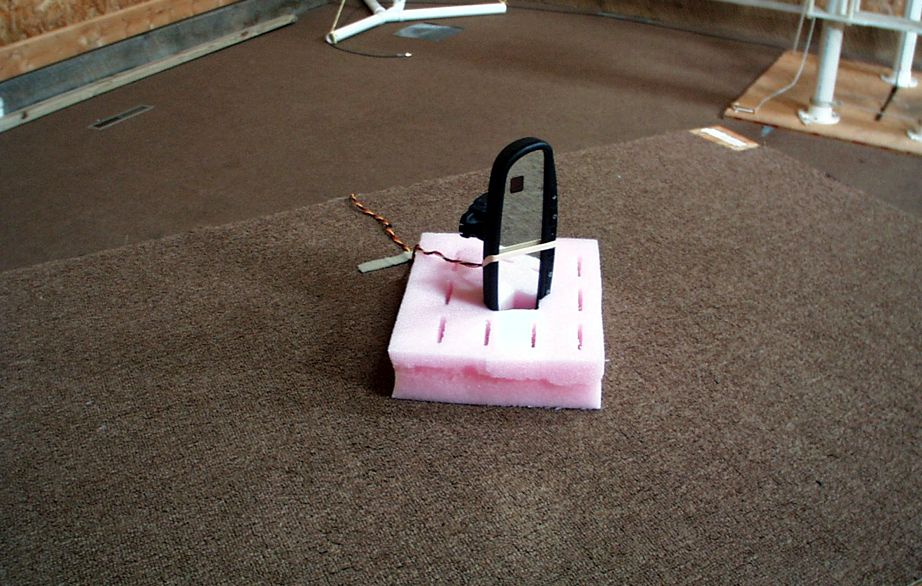
- Universal Garage Door Opener in Mirror
- Frequency Range
- 411.00000000 - 420.00000000
- Company
- Gentex Corporation
- Country
- United States
Documents & Files
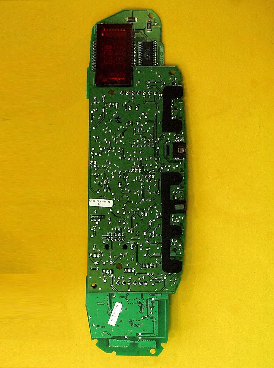
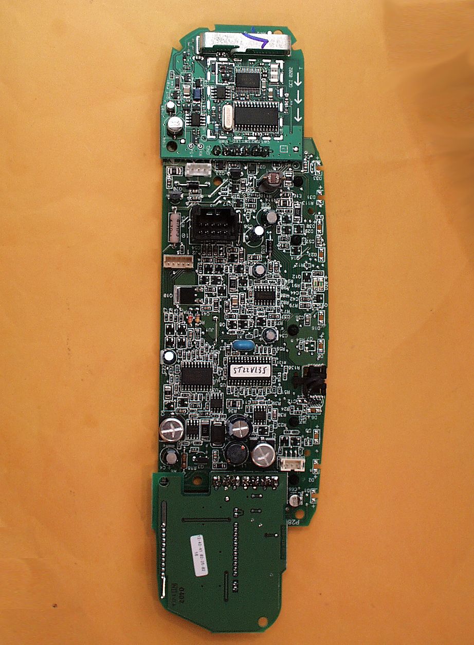
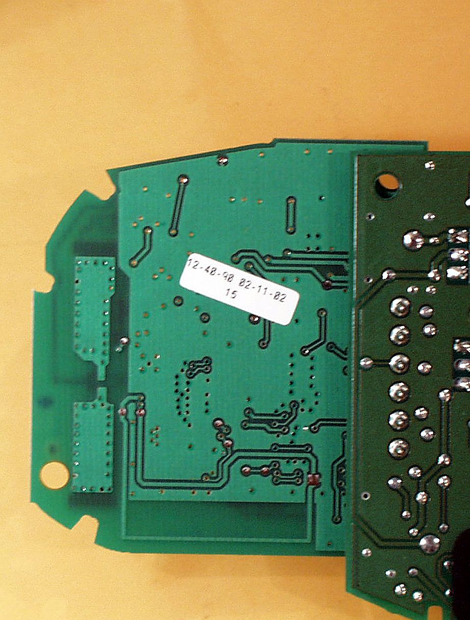
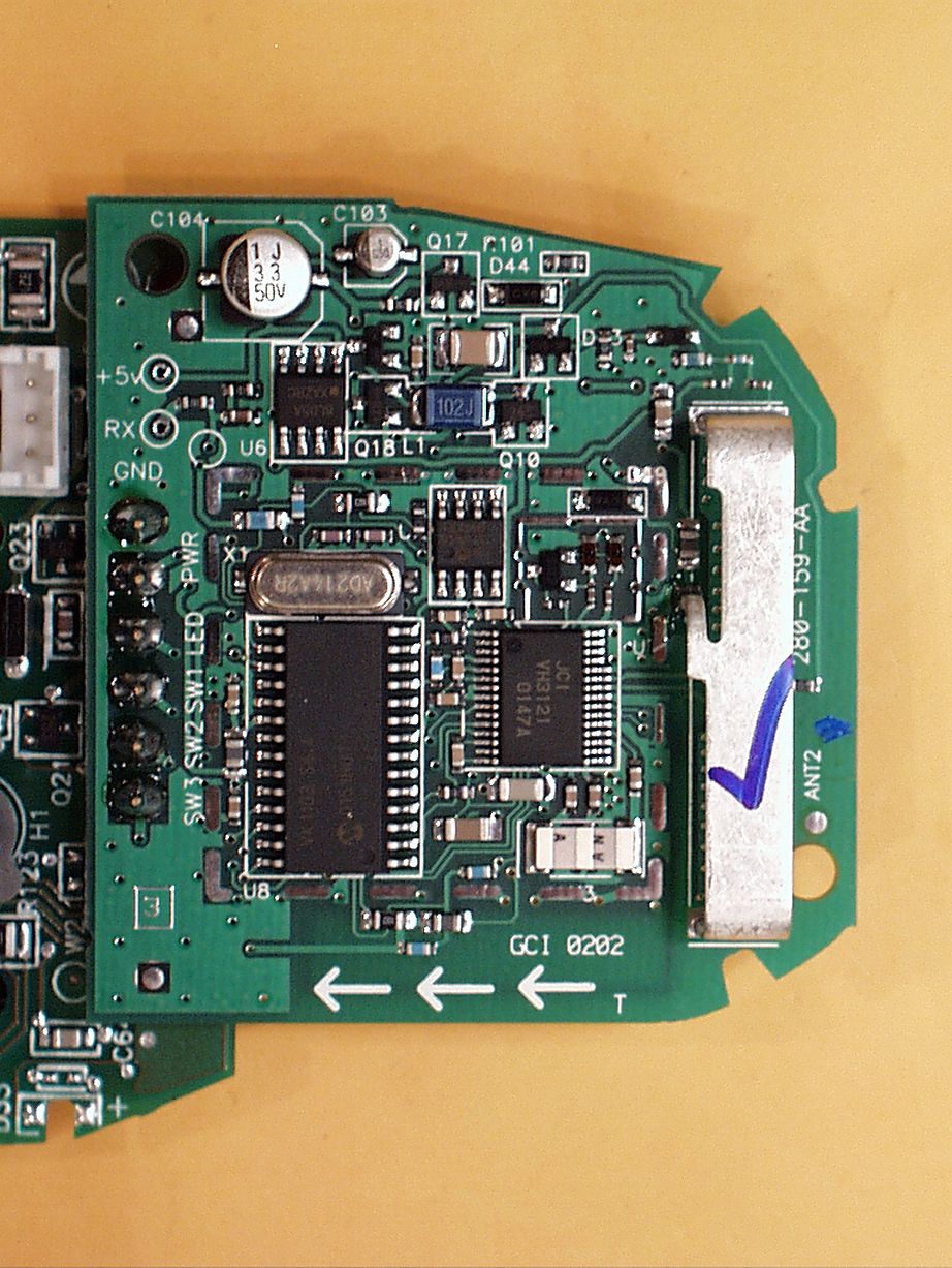
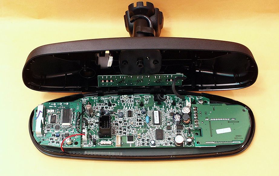
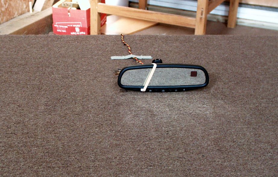
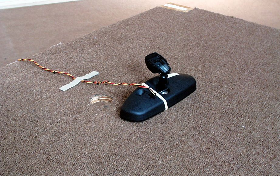
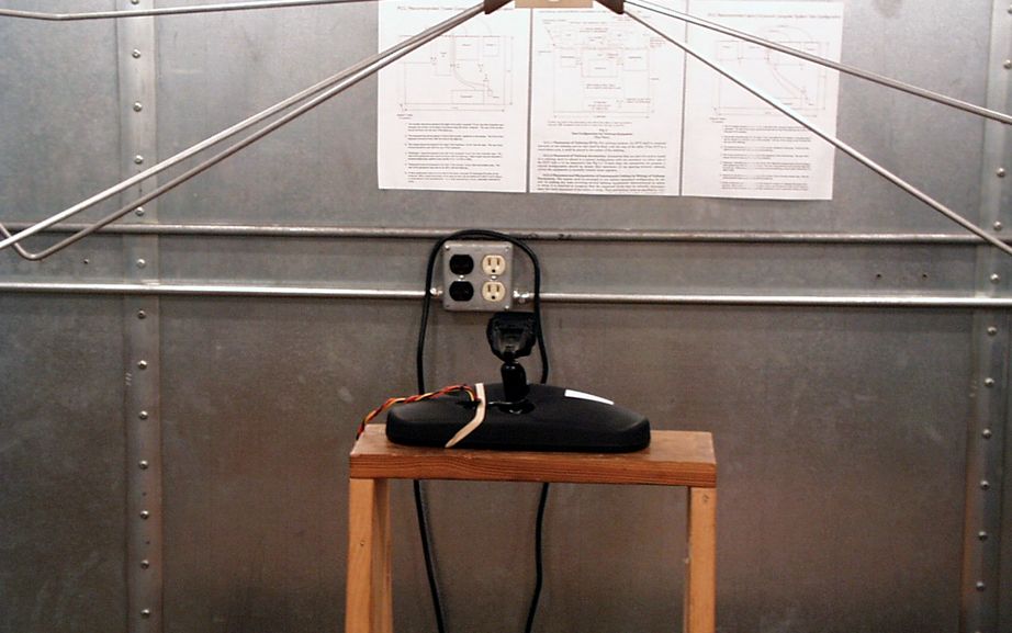
Document Text
Text extracted from the exhibit documents filed with the FCC. Open a document above to read the original.
Users Manual
EXHIBIT D: OWNER’S MANUAL [2.1033(A3)] Recommended Owners Manual for Automatic-Dimming NVS Mirror with Homelink® series Universal Garage Door Opener, Electronic Compass, Outside Temperature Display and LED Lights. Automatic-Dimming NVS Mirror with Homelink®, Electronic Compass, Outside Temperature Display and LED Lights Suggested Owner’s Manual Text April 2002 Automatic-Dimming Night Vision Safety (NVS) Mirror The NVS Mirror in your vehicle is the most advanced way to eliminate dangerous and annoying glare in the rearview mirror during any driving situation. For more information regarding NVS mirrors and other applications, please refer to the Gentex website – www.gentex.com. Precautions The NVS Mirror automatically reduces glare during driving conditions based upon light levels monitored in front of the vehicle and from the rear of the vehicle. These light sensors are visible through openings in the front and rear of the mirror case. Any object that would obstruct either light sensor will degrade the automatic dimming control feature. Operation The NVS Mirror operates automatically whenever the vehicle ignition is ON. The status of the automatic dimming feature is indicated by a green light on the face of the mirror. To turn the automatic dimming feature off, press and hold the button with the symbol for more than 9 seconds but less than 12 seconds. The indicator light will turn off to indicate that the automatic dimming feature is off. To turn the automatic dimming feature on, press and hold the button with the symbol for more than 9 seconds but less than 12 seconds again. The indicator light will also turn on. If the automatic dimming feature is off when the vehicle ignition is turned off, the automatic dimming feature will become active when the vehicle ignition is turned back on. Electronic Compass and Outside Temperature Display The NVS Mirror in your vehicle is also equipped with a display the shows the vehicle heading using the 8 basic cardinal headings (N, NE, E, SE, etc.). This NVS Mirror also includes a display of the outside temperature. For more information regarding these features in the NVS mirrors, please refer to the Gentex website – www.gentex.com. Electronic Compass with Outside Temperature Mirror Operation The Compass and Outside Temperature display operates automatically whenever the vehicle ignition is ON. To turn the display feature off, press the button with the symbol. To turn the display feature on, press the button with the symbol again. If the compass and outside temperature display feature is off when the vehicle ignition is turned off, the display feature will turn on again when the vehicle ignition is turned back on. To adjust the outside temperature units (°F or °C) setting press and hold the button for more than 3 seconds. The °F (or °C) will start flashing. Press the button until the correct units are displayed. Wait a few seconds and the mirror will display the current and compass heading and the outside temperature using the selected units. There is a difference between magnetic north and true north. The compass in the mirror can compensate for this difference when it knows what region in which it is operating. This is set either by the dealer or by the user. These operating regions or zones for the continental United States are shown in the figure below. To adjust the zone setting press and hold the button with the symbol for more than 12 seconds. Determine the appropriate zone number based upon your current location and the map provided above. Press and hold the button until the new zone setting appears on the display (note: the numbers will repeat, ...13, 14, 15, 1, 2, ...). Release the button and within about 5 seconds the compass will start displaying a compass direction again. There are some conditions that can cause changes to the vehicle magnets. Items such as installing a ski rack or a CB antenna or even some body repair work on the vehicle can cause changes to the vehicle's magnetic field. In these situations, the compass will need to be re-calibrated to quickly correct for these changes. To re-calibrate the compass, press and hold the button for more than 15 seconds. When the compass memory is cleared a “C” will appear in the display. To calibrate the compass, drive the vehicle is 3 complete circles at less than five mph. To adjust the zone setting press and hold the button with the symbol for more than 3 seconds. LED Light Operation The LED lights in the bottom of the mirror provide interior lighting under a variety of different circumstances. In most cases, the LED lights are controlled by the same vehicle control module that operates the other interior lights of the vehicle. However, these LED lights can also be controlled by the operator by simply pressing the button. These lights are operational when the vehicle is ON or OFF (please note that there may be a slight delay when turning the LED lights on while the vehicle is OFF). HomeLink ® Universal Transceiver The HomeLink ® Universal Transceiver included in your NVS Mirror with Homelink® provides a convenient way to replace up to three hand-held transmitters with a single built-in component. This innovative feature will learn the radio frequency codes of most current transmitters used to activate devices such as garage doors, entry door locks, estate gates, security systems, and home or office lighting. For additional information on HomeLink and/or HomeLink compatible products, call 1-800-355-3515 or refer to the HomeLink web site at www.homelink.jci.com. Precautions When programming the HomeLink Universal Transceiver to a garage door opener or entry gate, make sure that people and objects are out of the way to prevent potential harm or damage. Do not use the HomeLink Universal Transceiver with any garage door opener that lacks the safety stop and reverse feature as required by federal safety standards. (This includes any garage door opener model manufactured before April 1,…
Text truncated - open the document above for the full version.
Cover Letter(s)
AHD EMC Lab, 92723 M152, Dowagiac, MI 49047, (616) 424-7014 TCB_CvrLttr1.doc Cover / Confidentiality Request Letter: Page 1 of 2 NVLAP ACCREDITED NARTE Certified Engineer Professional Engineer ELITE Electronic Engineering April 20, 2002 TCB Services 1516 Centre Circle Downers Grove, IL 60515-1082 Re: Application for Certification of Gentex Corporation Transmitter under 47CFR 15.231. FCC ID: NZLLCTHL3 Gentlemen: On behalf of the applicant, Gentex Corporation, please find attached the submittal materials for certification of the Universal Garage Door Opener in a “super” Mirror with Compass, Temperature displays, and high intensity LED lights. The model is NZLLCTHL3. This unit is capable of learning the current garage door transmit frequencies from 288MHz through 420MHz except in the forbidden frequency regions. Pursuant to 47CRF 0.459, Gentex Corporation requests that these listed exhibits be held confidential. Circuit Block Diagrams page 2 of Exhibit B Theory/Description of Operation, page 3 of Exhibit B Schematics pages 5 through 12 of Exhibit B The complete List of the Exhibits in this submittal package appears on Page 2 of this cover letter. The enclosed CD contains the electronic copies of the printed materials. A copy of a ‘Power of Attorney” is included to demonstrate that AHD has been authorized to provide the service of preparing this application. Your prompt consideration of this application for product certification will be greatly appreciated. Should you have any questions regarding the content of this report, kindly contact me. Sincerely, Ted Chaffee, Technical Lab Manager Narte Certified Engineer, #EMC-002025-NE tel/fax: 616. 424.7014 email: [email protected], or [email protected] Test report #0200514F FCC 15.231 for NZLLCTHL3 FCC ID: NZLLCTHL3 Tested March 15, 2002 AHD EMC Lab, 92723 M152, Dowagiac, MI 49047, (616) 424-7014 TCB_CvrLttr1.doc Cover / Confidentiality Request Letter: Page 2 of 2 Table of Contents Cover Letter / Table of Contents Total Pages 2 EXHIBIT A: ID Label / Location [2.925,2.926,2.1033(b2,7),15.19(a3)] Total Pages 2 EXHIBIT B: Description of Product [2.1033(b6)] Total Pages 1 Circuit Block Diagram [2.1033(b5)] Total Pages 1 Description of Operation [2.1033(b4)] Total Pages 2 Schematics [2.1033(b5)] EXB_schematic.pdf Total Pages 8 EXHIBIT C: Product photos eight photos Total Pages 9 : Interior & Printed Circuit Boards [2.1033(b7)] Five photos EXC_3PCBtop.jpg, EXC_3PCBbtm.jpg, EXC_HL3PCBtop.jpg, EXC_HL3PCBbtm.jpg, EXC_InMirror.jpg Exterior views [2.1033(b7)] Four photos EXC_Mirrorfrnt.jpg, EXC_Mirrorrear.jpg, EXC_Mirrorbtm.jpg EXHIBIT D: User’s Manual EXD_OEMUserManual.doc Total Pages 6 EXHIBIT E: Setup photos [2.1033(b8)] Four photos Total Pages 5 EXE_pretest.jpg, EXE_side.jpg, EXE_end.jpg, EXE_flat.jpg Report of Measurements [2.1033(b6)] Total Pages 28 Table of Contents Page 2 Manufacturer/Applicant [2.1033(b1)] Page 4 Measurement/Test Facility & Equipment Page 4 Configuration/Setup [2.1033(b8)] Page 5 Test Standards / Methods Used [2.1033(b6)] Page 8 Test Methodology [2.1033(b6)] Page 8 Test Data [2.1033(b6)] Summary of Results Page 6 Level vs Supply Voltage [15.31(e)] Page 14 Occupied Bandwidth Page 15 Radiated Field Strength [15.231(b)] Page 17 Misc. EXHIBIT: RF Exposure Information [2.1093(c)] Total Pages 1 Tune-up Information [2.1033(b5] Total Pages 1
ID Label/Location Info
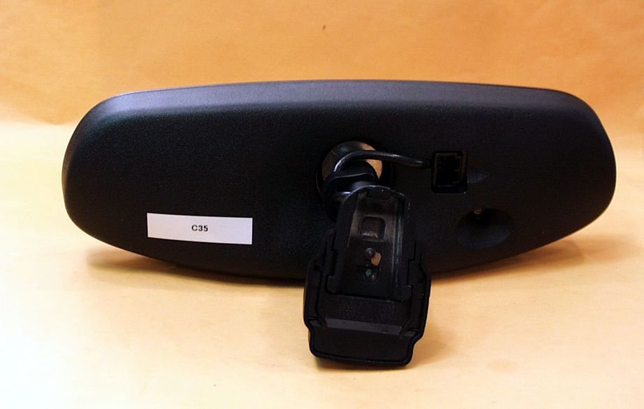
Test report #0200514F FCC 15.231 for NZLLCTHL3 FCC ID: NZLLCTHL3 Tested March 15, 2002 AHD EMC Lab, 92723 M152, Dowagiac, MI 49047, (616) 424-7014 EXA_Label.doc Exhibit A: Page 1 of 2 EXHIBIT A: EQUIPMENT LABEL [2.925, 2.926, 2.1033(B2,7), 15.19(A3)] LABEL EXAMPLE For the label drawing refer to picture file “EXA_Label.jpg” The FCC Identifier assigned to the EUT is FCC ID: NZLLCTHL3. This number will be molded into the rear of the mirror housing. Because of the size and location of the transmitter portion of the product, the following statements will appear in the user’s manual. Refer to Exhibit D for the entire text of the user’s manual. “This device complies with FCC rules Part 15. Operation is subject to the following two conditions: (1) This device may not cause harmful interference, and (2) This device must accept any interference that may be received including interference that may cause undesired operation. WARNING: The transmitter has been tested and complies with FCC and DOC/MDC rules. Changes or modifications not expressly approved by the party responsible for compliance could void the user’s authority to operate the device.” FCC ID Number LOCATION The information will be molded onto the outside of the NZLLCTHL3 plastic housing. Page 1 of 1 4/26/2002file://C:\TCB%20Certifications\FCC%20Work\AHD\Gentex\NZLLCTHL3\TCBEX_a\EX...
RF Exposure Info
Test report #0200514F FCC 15.231 for NZLLCTHL3 FCC ID: NZLLCTHL3 Tested March 15, 2002 AHD EMC Lab, 92723 M152, Dowagiac, MI 49047, (616) 424-7014 EXmisc_RFexpose.doc Misc. EXHIBIT: Page 1 of 2 MISC. EXHIBIT: RF EXPOSURE INFORMATION [2.1093(C)] The manufacturer and applicant: GENTEX CORPORATION 600 N. Centennial St. Zeeland, Michigan 49464 Product: NVSu Mirror with Homelink® III Universal Garage Door Opener with Electronic Compass, Outside Temperature Display, and LED lighting for vehicle interior. Model: NZLLCTHL3 Applicable Rules: 47CFR Part 15.231 Pursuant to 47CFR Part 1.1307(b), 47CFR Part 2.1091(c), and 47CFR Part 2.1093(c) this transmitting device, compliant to 47CFR Part 15.231, is categorically excluded from evaluation regarding the Maximum Permissible Exposure of RF energy.
Test Report
Test report #0100410F FCC 15.231 for NZLLCTHL3 FCC ID: NZLLCTHL3 Tested March 15, 2002 AHD EMC Lab, 92723 M152, Dowagiac, MI 49047, (616) 424-7014 EXE_TestRprt.doc EXHIBIT E: Page 1 of 30 EXHIBIT E: REPORT OF MEASUREMENTS [2.1033(B6)] Test Report for FCC ID: NZLLCTHL3 FCC Part 2.1031, Part 15 Subpart C(15.231) Report #0200514F Issued 04/15/02 MODEL NZLLCTHL3 NVSu MIRROR WITH HOMELINKq III TRANSMITTER, ELECTRONIC COMPASS, TEMPERATURE, & LED LIGHTING Prepared for: Mr. Brian Perschbacher Gentex Corporation 600 N. Centennial St. Zeeland, MI 49464 Test Date(s): March 14-15, 2002 data recorded by witnessed by Ted Chaffee, NCE Brian Perschbacher Test Engineer, AHD This report prepared by: Ted Chaffee, NCE Technical Manager/Test Engineer, AHD Test report #0200514F FCC 15.231 for NZLLCTHL3 FCC ID: NZLLCTHL3 Tested March 15, 2002 AHD EMC Lab, 92723 M152, Dowagiac, MI 49047, (616) 424-7014 EXE_TestRprt.doc EXHIBIT E: Page 2 of 30 TABLE OF CONTENTS EXHIBIT E: Report of Measurements [2.1033(b6)].................................................................................1 TABLE OF CONTENTS................................................................................................................2 Statements Concerning this Report................................................................................................3 Manufacturer/Applicant [2.1033(b1)]..............................................................................................4 Measurement/Test Site Facility & Equipment.................................................................................4 Test Site [2.948, 2.1033(b6)]...............................................................................................4 Measurement Equipment Used [2.947(d), 15.31(b)].................................................................4 Tested Configuration /Setup: [2.1033(b8)].......................................................................................5 Support Equipment & Cabling................................................................................................5 Setup Diagram......................................................................................................................5 Summary of Results:....................................................................................................................6 Changes made to achieve compliance....................................................................................8 Standards Applied to Test: [2.1033(b6)]..........................................................................................8 Test Methodology: [2.1033(b6)].....................................................................................................8 FORMULAS AND SAMPLE CALCULATIONS:.......................................................................10 Test Data [2.1033(b6)]................................................................................................................12 Modulation Characteristics...................................................................................................12 Relative Emission Level vs. Supply Voltage [15.31(e)]............................................................14 Occupied Bandwidth [15.231(c)]...........................................................................................15 Restricted Bands: [15.205]..................................................................................................16 Radiated Field Strength Measurements: [15.231(b), 15.205]..................................................17 Radiated Field Strength Measurements.................................................................................19 Test report #0200514F FCC 15.231 for NZLLCTHL3 FCC ID: NZLLCTHL3 Tested March 15, 2002 AHD EMC Lab, 92723 M152, Dowagiac, MI 49047, (616) 424-7014 EXE_TestRprt.doc EXHIBIT E: Page 3 of 30 Statements Concerning this Report NVLAP Accreditation: NVLAP Lab Code 200129-0 The scope of AHD accreditation is the conducted emissions, radiated emissions test methods of: IEC/CISPR 22: Limits and methods measurement of radio disturbance characteristics of information technology equipment. FCC Method – 47 CFT Part 15 – Digital Devices. AS/NZS 3548: Electromagnetic Interference – Limits and Methods of Measurement of Information Technology Equipment. IEC61000-4-2 and Amend.1: ElectroStatic Discharge Immunity Subcontracted Testing: This report does not contain data produced under subcontract. Test Traceability: The calibration of all measuring and test equipment and the measured data using this equipment are traceable to the National Institute for Standards and Technology (NIST). Limitations on results: The test results contained in this report relate only to the Item(s) tested. Any electrical or mechanical modification made to the test item subsequent to the test date shall invalidate the data presented in this report. Any electrical or mechanical modification made to the test item subsequent to this test date shall require an evaluation to verify continued compliance. Limitations on copying: This report shall not be reproduced, except in full, without the written approval of AHD. Limitations of the report: This report shall not be used to claim product endorsement by NVLAP, FCC, or any agency of the US Government. Statement of Test Results Uncertainty: Following the guidelines of NAMAS publication NIS81 and NIST Technical Note 1297, the Measurement Uncertainty at a 95% confidence level is determined to be: ± 1.4 dB Test report #0200514F FCC 15.231 for NZLLCTHL3 FCC ID: NZLLCTHL3 Tested March 15, 2002 AHD EMC Lab, 92723 M152, Dowagiac, MI 49047, (616) 424-7014 EXE_TestRprt.doc EXHIBIT E: Page 4 of 30 Manufacturer/Applicant [2.1033(b1)] The manufacturer and applicant: GENTEX CORPORATION 600 N. Centennial St. Zeeland, Michigan 49464 Measurement/Test Site Facility & Equipment Test Site [2.948, 2.1033(b6)] The AHD test facility is centered on 9 acres of rural prop…
Text truncated - open the document above for the full version.
Contact Information
Applicant
Brian Miller(Corporate Labs Group Leader - Wireless Regulatory)
Non-Technical Contact
AHDTed Chaffee
[email protected]1 616 424 7014
Test Firm
AHD EMC LaboratoryGordon Helm
Technical Specifications
| # | Rule Parts | Frequency Range | Power Output |
|---|---|---|---|
| 4 | 15.231 | 411 MHz - 420 MHz | - |
Other Applications from Gentex Corporation
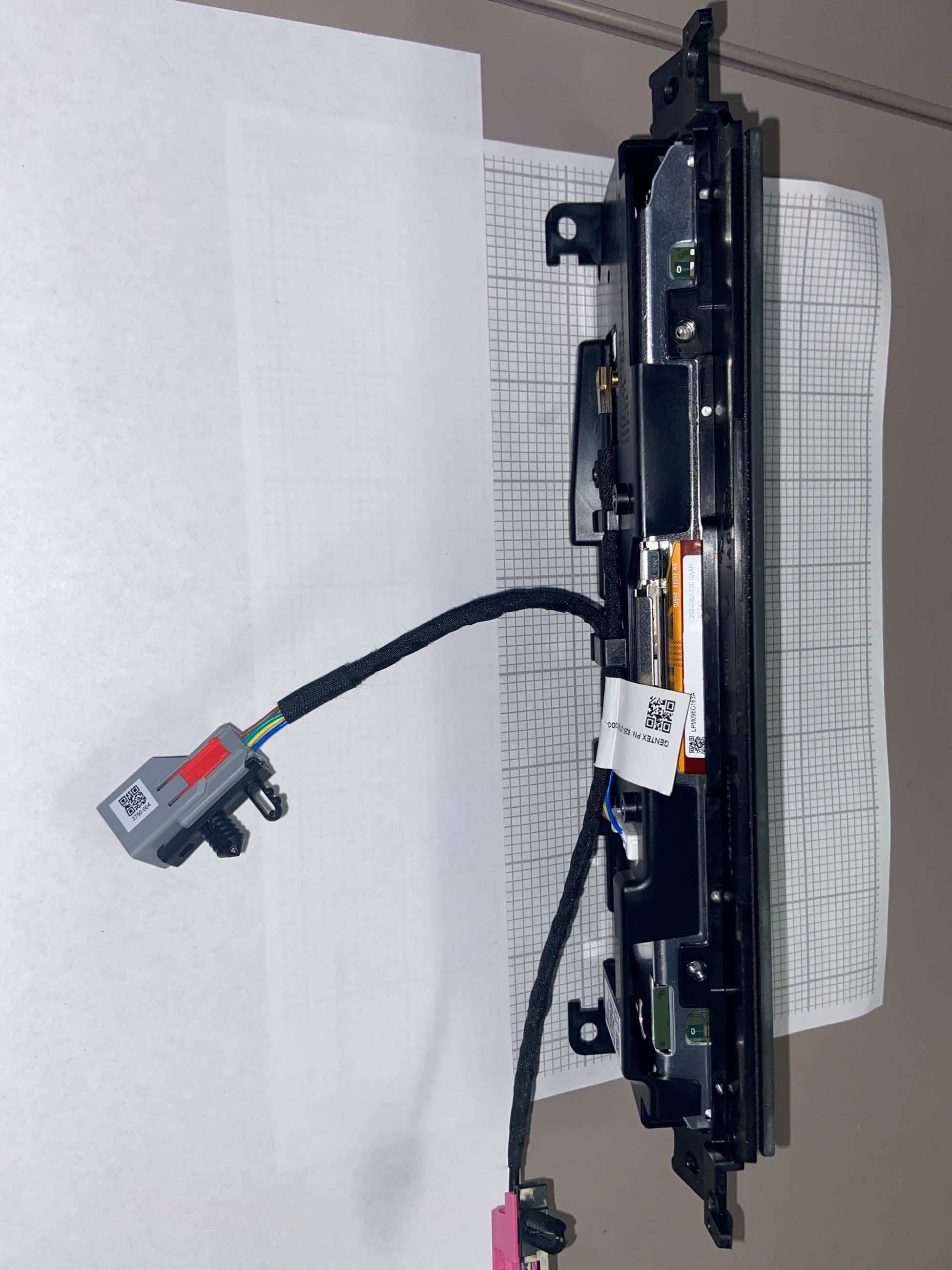
NZLRDHL6A
Jul 29, 2026Wireless Garage Door Opener
Equipment Class
CYY - Communications Receiver used w/Pt 15 Transmitter
NZLFDMHL6D
Jun 15, 2026Wireless Garage Door Opener
Equipment Class
DTS - Digital Transmission System
NZLFDMHL6B
May 18, 2026Wireless Garage Door Opener
Equipment Class
DSS - Part 15 Spread Spectrum Transmitter
NZLDEFRX6
May 04, 2026Default Receiver
Equipment Class
DTS - Digital Transmission System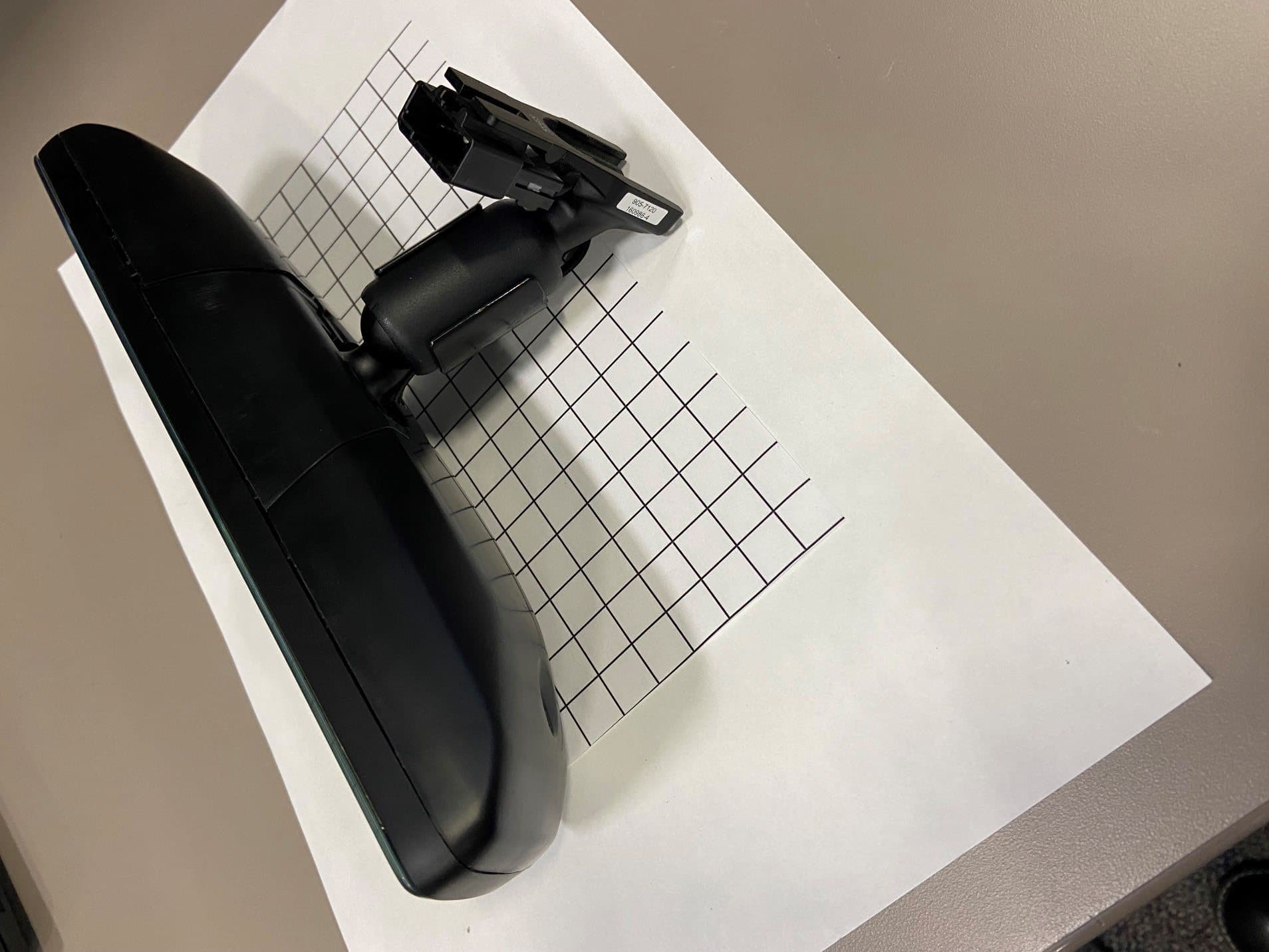
NZLFDMHL6A
Jan 12, 2026Wireless Garage Door Opener
Equipment Class
DTS - Digital Transmission System