NZLNI13HL4HomeLink TX
Gentex Corporation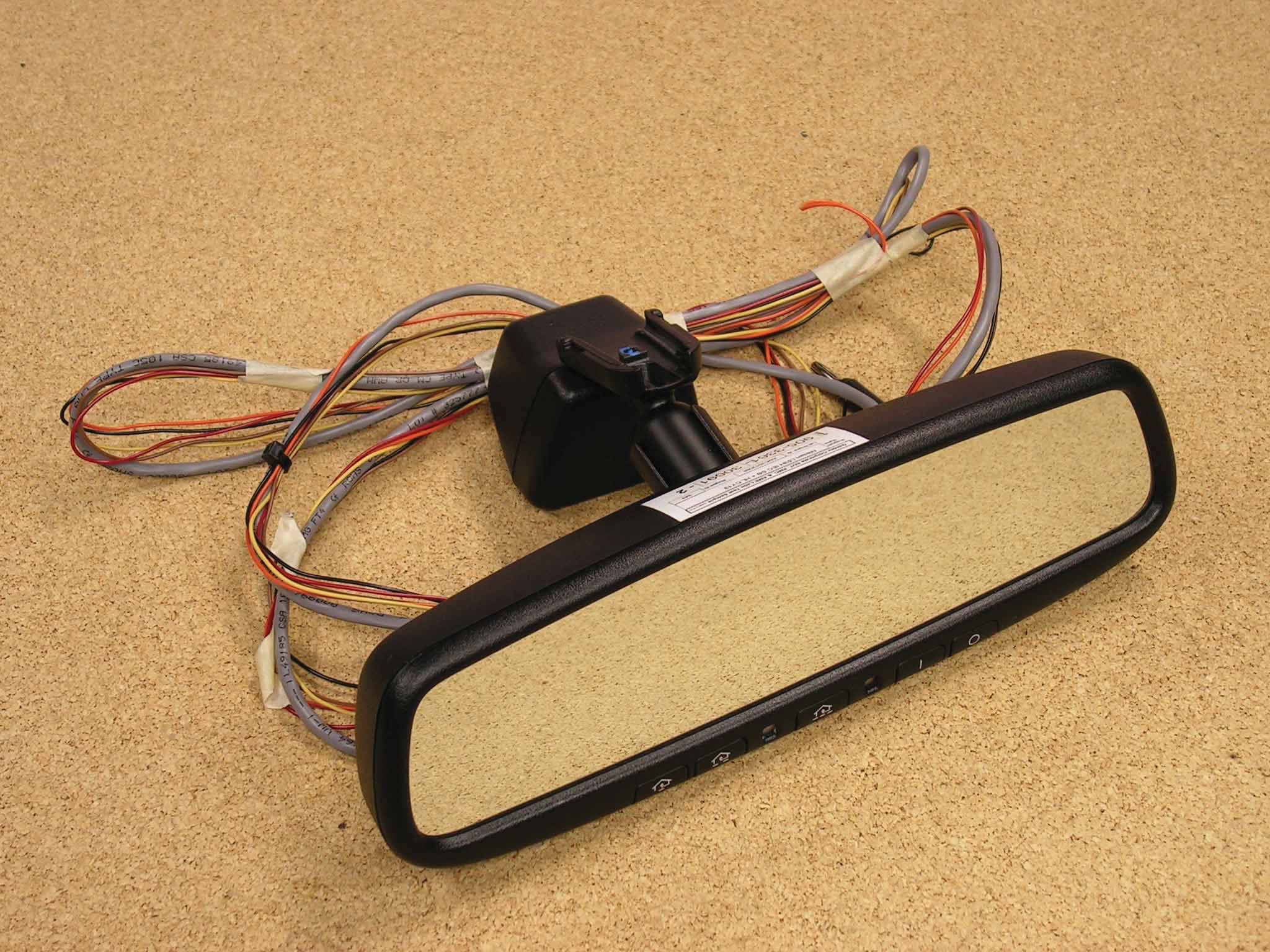
Click to zoom
Application Details
- Equipment Class
- DSC - Part 15 Security/Remote Control Transmitter
- Date of Grant
- Dec 13, 2012
- Application Purpose
- Original Equipment
- Date of Application
- Dec 11, 2012
- Equipment Note
- HomeLink TX
- Frequency Range
- 411.00000000 - 450.00000000
- Company
- Gentex Corporation
- Country
- United States
Documents & Files
Document Text
Text extracted from the exhibit documents filed with the FCC. Open a document above to read the original.
Users Manual
Programming and Information Guide The HomeLink Wireless Control System provides a convenient way to replace up to three hand- held radio-frequency (RF) transmitters used to activate devices such as gate operators, garage door openers, entry door locks, security systems, even home lighting. Additional HomeLink information can be found on the Internet at www.homelink.com . Precautions ! Before programming HomeLink to a garage door opener or gate operator, make sure that people and objects are out of the way of the device to prevent potential harm or damage. When programming a garage door opener, it is advised to park outside of the garage. Do not use HomeLink with any garage door opener that lacks safety stop and reverse features as required by U.S. federal safety standards (this includes any garage door opener model manufactured before April 1, 1982). A garage door that cannot detect an object - signaling the door to stop and reverse - does not meet current U.S. federal safety standards. For more information, contact HomeLink at: www.homelink.com . Certain garage door drives are incompatible with HomeLink Wireless Control System. If you have any difficulty programming, please contact the HomeLink® Hotline Assistance Center at 1- 800-355-3515. Retain the original transmitter of the RF device you are programming for use in other vehicles as well as for future HomeLink programming. It is also suggested that upon the sale of the vehicle, the programmed HomeLink buttons be erased for security purposes. Refer to “Erasing HomeLink Buttons”. Programming HomeLink Note: Some vehicles may require the ignition switch to be turned on or to the second (“accessories”) position for programming and/or operation of HomeLink. It is also recommended that a new battery be placed in the hand-held transmitter of the device being programmed to HomeLink for quicker training and accurate transmission of the radio-frequency signal. 1. Position the end of your hand-held transmitter 1–3 inches (5–14 cm) away from the HomeLink button you wish to program while keeping the indicator light in view. 2. Simultaneously press and hold both the chosen HomeLink and hand-held transmitter buttons until the HomeLink indicator light changes from a slow to a rapidly blinking light. Now you may release both the HomeLink and hand-held transmitter buttons. Note: Some devices may require you to replace this Programming Step 2 with procedures noted in the “Gate Operator / Canadian Programming” section. If the HomeLink indicator light does not change to a rapidly blinking light after performing these steps, contact HomeLink at www.homelink.com. 3. Firmly press, hold for five seconds and release the programmed HomeLink button up to two separate times to activate the door. If the door does not activate, press and hold the just- trained HomeLink button and observe the indicator light. • If the indicator light stays on constantly, programming is complete and your device should activate when the HomeLink button is pressed and released. • If the indicator light blinks rapidly for two seconds and then turns to a constant light continue with “Programming” steps 4-6 to complete the programming of a rolling code equipped device (most commonly a garage door opener). 4. At the garage door opener receiver (motor-head unit) in the garage, locate the “learn” or “smart” button. This can usually be found where the hanging antenna wire is attached to the motor-head unit. 5. Firmly press and release the “learn” or “smart” button. (The name and color of the button may vary by manufacturer.) There are 30 seconds to initiate step 6. 6. Return to the vehicle and firmly press, hold for two seconds and release the programmed HomeLink button. Repeat the “press/hold/release” sequence a second time, and, depending on the brand of the garage door opener (or other rolling code equipped device), repeat this sequence a third time to complete the programming process. HomeLink should now activate your rolling code equipped device. Gate Operator / Canadian Programming Canadian radio-frequency laws require transmitter signals to “time-out” (or quit) after several seconds of transmission – which may not be long enough for HomeLink to pick up the signal during programming. Similar to this Canadian law, some U.S. gate operators are designed to “time-out” in the same manner. If you live in Canada or you are having difficulties programming a gate operator or garage door opener by using the “Programming” procedures, replace “Programming HomeLink” step 2 with the following: Note: If programming a garage door opener or gate operator, it is advised to unplug the device during the “cycling” process to prevent possible overheating. 2. Continue to press and hold the HomeLink button while you press and release - every two seconds (“cycle”) your hand-held transmitter until the HomeLink indicator light changes from a slow to a rapidly blinking light. Now you may release both the HomeLink and hand-held transmitter buttons. Proceed with “Programming” step 3 to complete. Using HomeLink To operate, simply press and release the programmed HomeLink button. Activation will now occur for the trained device (i.e. garage door opener, gate operator, security system, entry door lock, home/office lighting, etc.). For convenience, the hand-held transmitter of the device may also be used at any time. In the event that there are still programming difficulties or questions, contact HomeLink at: www.homelink.com. Erasing HomeLink Buttons To erase programming from the three buttons (individual buttons cannot be erased but can be “reprogrammed” as outlined below), follow the step noted: • Press and hold the two outer HomeLink buttons until the indicator light begins to flash-after 10 seconds. Release both buttons. Do not hold for longer that 20 seconds. HomeLink is now in the train (or learning) mode and can be programmed at any time beginning with “Programming” - step 1. Reprogramming a Single HomeLink But…
Text truncated - open the document above for the full version.
Cover Letter(s)
Re: Certification for Gentex Transceiver Model/PN(s): NI13HL4 FCC ID: NZLNI13HL4 IC: 4112A-NI13HL4 POWER OF ATTORNEY A letter granting Valdis V. Liepa the Power of Attorney is on file and can be provided when so requested. November 9, 2012 Re: Certification for Gentex Transceiver Model/PN(s): NI13HL4 FCC ID: NZLNI13HL4 IC: 4112A-NI13HL4 STATEMENT OF MODIFICATIONS There were no modifications made to the DUT by this test laboratory. (Also see Section 3.1 of the attached Test Report). _____________________ Valdis V. Liepa Research Scientist
Cover Letter(s)
GENTEX CORPORATION 600 N. Centennial Street, Zeeland, MI 49464 Federal Communication Commission Equipment Approval Services, P.O. Box 358315 Pittsburgh, PA 15251‐5315 Attention: Authorization & Evaluation Division To whom it may concern, Gentex Corporation assures there are no means (either software or hardware) for the end user to change the operating parameters from those reported in the application. In addition, the commission will be notified, in writing, of any changes in the software or programming of the device that could affect the device’s RF characteristics. Sincerely, Craig Harder
Cover Letter(s)
Re: Certification for Gentex Transceiver FCC ID: NZLNI13HL4 IC: 4112A-NI13HL4 REQUEST FOR CONFIDENTIALITY Pursuant to FCC 47 CRF 0.457(d) and 0.459 and IC RSP-100, Section 10, Gentex requests that a part of the subject application be held confidential. Gentex has spent substantial effort in developing this product and it is one of the first of its kind in industry. Having the subject information easily available to "competition" would negate the advantage they have achieved by developing this product. Not protecting the details of the design will result in financial hardship. Type of Confidentiality Requested Exhibit Short Term Permanent (1) ID Label & Location Short Term Permanent (3) External Photos Short Term Permanent 1 (4) Block Diagram Short Term Permanent (5) Schematics Short Term Permanent (7) Test Setup Photos Short Term Permanent (8) User’s Manual Short Term Permanent (9) Internal Photos Short Term Permanent (10) Parts List & Placement Short Term Permanent (11) RF Exposure Short Term Permanent 2 (12) Description of Operation (partial) 1. Block Diagram includes internal oscillator frequency information that the manufacturer considers to be proprietary. 2. A portion of the Description of Operation exhibit contains proprietary information that Gentex wishes to remain confidential. A public description has also been provided that describes the operation of the device in more general terms. Permanent Confidentiality: Gentex requests the exhibits listed above as permanently confidential be permanently withheld from public review. Short-Term Confidentiality (FCC Only): Gentex requests the exhibits selected above as short term confidential be withheld from public view for a period of 45 days from the date of the Grant of Equipment Authorization and prior to marketing. If there are any questions regarding this request, please contact me at the above address or call 734-483-4211, fax 734-647-2106 or e-mail [email protected]. Sincerely, Valdis V. Liepa, Research Scientist University of Michigan
Test Report
University of Michigan Radiation Laboratory FCC Part 15, IC RSS-210/Gen - Test Report No. 417124-648 Page 1 of 23 The University of Michigan Radiation Laboratory 3228 EECS Building Ann Arbor, MI 48109-2122 Tel: (734) 764-0500 Fax: (734) 647-2106 Measured Radio Frequency Emissions From Gentex Corporation Transceiver FCC ID: NZLNI13HL4 IC: 4112A-NI13HL4 Test Report No. 417124-648 November 26, 2012 Copyright © 2012 For: Gentex Corporation 600 N. Centennial St., Zeeland, MI 49464 Contact: Craig Harder, [email protected] Phone: (616) 772-1590 Fax: (616) 748-8174 Testing supervised by: Measurements made by: Valdis V. Liepa Report Approved by:__________________________ Vald is V. Liepa Test report written by: Valdis V. Liepa Research Scientist Summary Tests for compliance with FCC Regulations, CFR 47, Part 15 and with Industry Canada RSS-210/Gen, were performed on a Gentex, FCC ID: NZLNI13HL4, IC: 4112A-NI13HL4. This device under test (DUT) is subject to the rules and regulations as a Universal Garage Door Opener Transceiver. As such, the DUT was trained to and fully tested for three duty factors (30%, 50%, and 80%) and at four frequencies (288 MHz, 310 MHz, 390 MHz, and 434 MHz). In testing completed on November 21, 2012, the DUT met the allowed limits for radiated emissions by 0.7 dB at the fundamental and by 7.4 dB a t the harmonics, in the worst case. Besides har monics there were no other significant spurious emissions found. It was also verified that the device does not tra nsmit in Restricted Bands. AC mains power conducted emissions limits do not apply as the device is powered from a 12VDC vehicular source. University of Michigan Radiation Laboratory FCC Part 15, IC RSS-210/Gen - Test Report No. 417124-648 Page 2 of 23 Table of Contents 1. Introduction ...................................................................................................................................... 3 2. Equipment Used ............................................................................................................................... 3 3. Device Under Test ........................................................................................................................... 4 3.1 Description & Block Diagram .............................................................................................. 4 3.2 Variants and Samples ............................................................................................................ 4 3.3 Modes of Operation .............................................................................................................. 4 3.4 Exemptions ........................................................................................................................... 4 3.5 EMC Relevant Modifications ............................................................................................... 4 4. Emissions Limits .............................................................................................................................. 5 4.1 Radiated Emissions Limits .................................................................................................... 5 5. Measurement Procedures ................................................................................................................. 6 5.1 Semi -Anechoic Chamber Radiated Emissions ...................................................................... 6 5.2 Outdoor Radiated Emissions ................................................................................................. 6 5.3 Radiated Field Computations ................................................................................................ 6 5.4 Indoor Power Line Conducted Emissions ............................................................................. 6 5.5 Supply Voltage Variation ...................................................................................................... 7 6. Test Results ...................................................................................................................................... 7 6.1 Radiated Emissions ............................................................................................................... 7 6.1.1 Correction for Pulse Operation ......................................................................................... 7 6.1.2 Emission Spectrum ........................................................................................................... 7 6.1.3 Emission Bandwidth ......................................................................................................... 7 6.1.4 Verification of Non-operation in Restricted Bands........................................................... 8 6.1.5 Learning receiver emissions .............................................................................................. 8 6.1.6 Supply Voltage and Supply Voltage Variation ................................................................. 8 6.2 AC Mains Conducted Emissions .......................................................................................... 8 University of Michigan Radiation Laboratory FCC Part 15, IC RSS-210/Gen - Test Report No. 417124-648 Page 3 of 23 1. Introduction This Gentex Transceiver was tested for compliance with FCC Regulations, Part 15, adopted under Docket 87-389, April 18, 1989 as subsequently amended, and with Industry Canada RSS-210/Gen, Issue 8. T ests were performed at the University of Michigan Radiation Laboratory Willow Run Test Range following the procedures described in ANSI C63.4-2003 "Methods of Measurement of Radio-Noise Emissions from Low -Voltage Electrical and Electronic Equipment in the Range of 9 kHz to 40 GHz". The Site description and attenuation characteristics of the Open Site facility are on file with FCC Laboratory, Columbia, Maryland (FCC Reg. No: 91050) and with Industry Canada, Ottawa, ON (File Ref. No: IC 2057A-1). 2. Equipment Used The test equipment c…
Text truncated - open the document above for the full version.
Contact Information
Applicant
Brian Miller(Corporate Labs Group Leader - Wireless Regulatory)
Technical Contact
University of Michigan / EECSValdis V. Liepa
[email protected]7344834211
1301 Beal Ave. · Ann Arbor, Michigan · United States
Test Firm
University of MichiganValdis Liepa
Technical Specifications
| # | Rule Parts | Frequency Range | Power Output |
|---|---|---|---|
| 4 | 15.231 | 411 MHz - 450 MHz | - |
Other Applications from Gentex Corporation
NZLRDHL6A
Jul 29, 2026Wireless Garage Door Opener
Equipment Class
CYY - Communications Receiver used w/Pt 15 Transmitter
NZLFDMHL6D
Jun 15, 2026Wireless Garage Door Opener
Equipment Class
DTS - Digital Transmission System
NZLFDMHL6B
May 18, 2026Wireless Garage Door Opener
Equipment Class
DSS - Part 15 Spread Spectrum Transmitter
NZLDEFRX6
May 04, 2026Default Receiver
Equipment Class
DTS - Digital Transmission System
NZLFDMHL6A
Jan 12, 2026Wireless Garage Door Opener
Equipment Class
DTS - Digital Transmission System