NZLPZLHL4Universal Garage Door Opener in Mirror
Gentex Corporation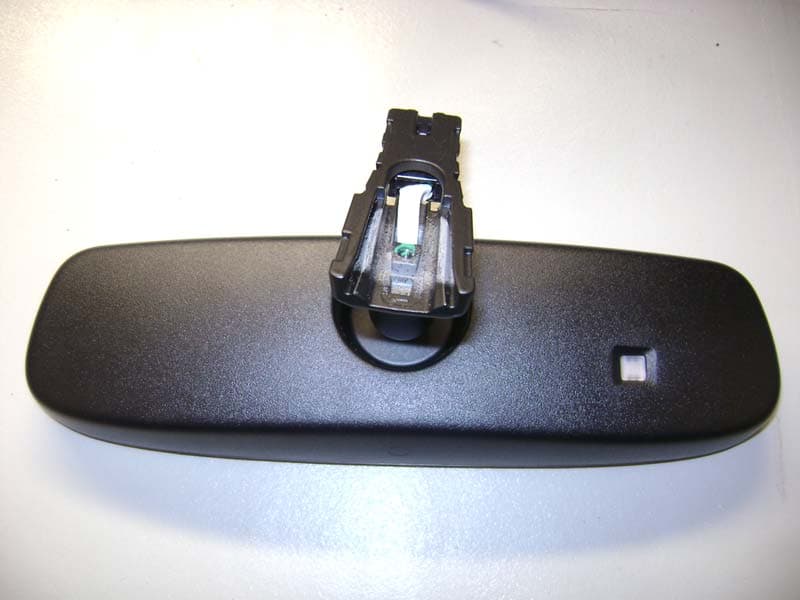
Click to zoom
Application Details
- Equipment Class
- DSR - Part 15 Remote Control/Security Device Transceiver
- Date of Grant
- Mar 08, 2012
- Application Purpose
- Original Equipment
- Date of Application
- Mar 08, 2012
- Equipment Note
- Universal Garage Door Opener in Mirror
- Frequency Range
- 411.00000000 - 420.00000000
- Company
- Gentex Corporation
- Country
- United States
Documents & Files
Document Text
Text extracted from the exhibit documents filed with the FCC. Open a document above to read the original.
Users Manual
Suggested Owner’s Manual Text for Gentex Auto-Dimming Mirror with HomeLink ® Automatic–Dimming Mirror with HomeLink ® Your new vehicle comes with an Automatic-Dimming Mirror with an Integrated HomeLink ® Wireless Control System. During nighttime driving, this safety feature will automatically detect and eliminate dangerous rearview mirror glare while the HomeLink ® Universal Transceiver allows you to activate your garage door(s), estate gate, home lighting, etc. Automatic-Dimming Mirror The Automatic-Dimming Mirror in your vehicle is the most advanced way to eliminate dangerous and annoying glare in the rearview mirror during any driving situation. For more information regarding Gentex Corporation mirrors and other applications, please refer to the Gentex website: www.gentex.com . Precautions The Automatic-Dimming Mirror automatically reduces glare during driving conditions based upon light levels monitored in front of the vehicle and from the rear of the vehicle. These light sensors are visible through openings in the front and rear of the mirror case. Any object that would obstruct either light sensor will degrade the automatic dimming control feature. Automatic-Dimming Function To protect your vision during nighttime driving, your mirror will automatically dim upon detecting glare from the vehicles traveling behind you. The auto-dimming function is active when the Ignition is “ON” and cannot be disabled. Suggested Owner’s Manual Text for Gentex Auto-Dimming Mirror with HomeLink ® Integrated HomeLink ® Wireless Control System The HomeLink ® Wireless Control System provides a convenient way to replace up to three hand-held radio-frequency (RF) transmitters with a single built-in device. This innovative feature will learn the radio frequency codes of most current transmitters to operate devices such as gate operators, garage door openers, entry door locks, security systems, even home lighting. Both standard and rolling code-equipped transmitters can be programmed by following the outlined procedures. Additional HomeLink ® information can be found at: www.homelink.com or by calling 1-800-355-3515. Precautions Before programming HomeLink ® to a garage door opener or gate operator, make sure that people and objects are out of the way of the device to prevent potential harm or damage. Do not use HomeLink ® with any garage door opener that lacks the safety stop and reverse features as required by U.S. federal safety standards (this includes any garage door opener model manufactured before April 1, 1982). A garage door that cannot detect an object - signaling the door to stop and reverse - does not meet current U.S. federal safety standards. Using a garage door opener without these features increases the risk of serious injury or death. Retain the original transmitter of the RF device you are programming for use in other vehicles as well as for future HomeLink ® programming. It is also suggested that upon the sale of the vehicle, the programmed HomeLink ® buttons be erased for security purposes. Programming HomeLink ® Notes: • When programming a garage door opener, it is advised to park the vehicle outside of the garage. • It is recommended that a new battery be placed in the hand-held transmitter of the device being programmed to HomeLink ® for quicker training and accurate transmission of the radio-frequency signal. • Some vehicles may require the ignition switch to be turned to the second (or “accessories”) position for programming and/or operation of HomeLink. • In the event that there are still programming difficulties or questions after following the programming steps listed below, contact HomeLink ® at: www.homelink.com or 1–800–355–3515. Standard Programming To train most devices, follow these instructions: 1. For first-time programming, press and hold the two outside buttons, HomeLink ® Channel 1 and Channel 3 Buttons, until the indicator light begins to flash (after 20 seconds). Release both buttons. Do not hold the buttons for longer than 30 seconds. 2. Position the end of your hand-held transmitter 1–3 inches (5–14 cm) away from the HomeLink ® buttons while keeping the indicator light in view. Suggested Owner’s Manual Text for Gentex Auto-Dimming Mirror with HomeLink ® 3. Simultaneously press and hold both the HomeLink ® and hand-held transmitter button. DO NOT release the buttons until step 4 has been completed. 4. While continuing to hold the buttons the red Indicator Status LED will flash slowly and then rapidly after HomeLink ® successfully trains to the frequency signal from the hand-held transmitter. Release both buttons. 5. Press and hold the just-trained HomeLink ® button and observe the red Status Indicator LED. If the indicator light stays on constantly, programming is complete and your device should activate when the HomeLink ® button is pressed and released. 6. To program the remaining two HomeLink ® buttons, follow steps 2 through 5. Rolling Code Programming Rolling code devices which are “code-protected” and manufactured after 1996 may be determined by the following: • Reference the device owner’s manual for verification. • The handheld transmitter appears to program the HomeLink Universal Transceiver but does not activate the device. • Press and hold the trained HomeLink button. The device has the rolling code feature if the indicator light flashes rapidly and then turns solid after 2 seconds. To train rolling code devices, follow these instructions: 1. At the garage door opener receiver (motor-head unit) in the garage, locate the “learn” or “smart” button. This can usually be found where the hanging antenna wire is attached to the motor-head unit. Exact location and color of the button may vary by garage door opener brand. If there is difficulty locating the training button, reference the device owner’s manual or please visit our Web site at www.homelink.com. 2. Firmly press and release the “learn” or “smart” button (which activates the “training light”). Note: Ther…
Text truncated - open the document above for the full version.
ID Label/Location Info
FCC 15.231 for PZLHL4 FCC ID: NZLPZLHL4 Tested January 31, 2012 Gentex Corporation 600 N. Centennial Dr, Zeeland, Mi 49464 (616)772-1800 Label Example LABEL EXAMPLE For additional Information refer to picture below. The FCC Identifier assigned to the EUT is FCC ID: NZLPZLHL4. This number will be placed on a sticker that will be affixed to the rear of the mirror mounting arm. Because of the size and location of the transmitter portion of the product, the following statements will appear in the user’s manual. Refer to Example D for the entire text of the user’s manual. From Section 15.19 Information to the user: NOTE: This device complies with Part 15 of the FCC Rules. Operation is subject to the following two conditions: (1) This device may not cause harmful interference, and (2) this device must accept any interference received, including interference that may cause undesired operation. FCC ID Number LOCATION The information will be lased into the rear of the case to one side of the mounting arm on the outside of the PZLHL4 mirror assembly.
Test Report
Engineering Test Report No. 1200265-01 Measurement of RF Emissions from a Model PZLHL4 and OBI2HL4 Transceiver For Gentex Corporation 600 N. Centennial Street Zeeland, MI 49464 P.O. Number 1294263 Date Tested January 31 2012 through February 27, 2012 Test Personnel Richard E. King, Mark Longinotti Test Specification FCC "Code of Federal Regulations” Title 47 Part15, Subpart C Industry Canada RSS-GEN Industry Canada RSS-210 Test Report By: Mark Longinotti EMC Engineer Requested By: Rohn Kunnen Gentex Corporation Approved By: Raymond J. Klouda Registered Professional Engineer of Illinois - 44894 Elite Electronic Engineering, Inc. 1516 Centre Circle Downers Grove, IL 60515 Tel : (630) 495-9770 Fax: (630) 495-9785 www.elitetest.com Engineering Test Report No. 1200265-01 TABLE OF CONTENTS PARAGRAPH DESCRIPTION OF CONTENTS PAGE NO. THIS REPORT SHALL NOT BE REPRODUCED, EXCEPT IN FULL, WITHOUT THE WRITTEN APPROVAL OF ELITE ELECTRONIC ENGINEERING INCORPORATED. Page 2 of 138 1. Introduction ................................................................................................................................................... 5 1.1. Scope of Tests ..................................................................................................................................... 5 1.2. Purpose ............................................................................................................................................... 5 1.3. Deviations, Additions and Exclusions .................................................................................................. 5 1.4. EMC Laboratory Identification ............................................................................................................. 5 1.5. Laboratory Conditions.......................................................................................................................... 5 2. Applicable Documents .................................................................................................................................. 5 3. EUT Setup and Operation ............................................................................................................................ 5 3.1. General Description ............................................................................................................................. 5 3.1.1. Power Input ................................................................................................................................. 6 3.1.2. Peripheral Equipment ................................................................................................................. 6 3.1.3. Signal Input/Output Leads .......................................................................................................... 6 3.1.4. Grounding ................................................................................................................................... 6 3.2. Operational Mode ................................................................................................................................ 6 3.3. EUT Modifications ................................................................................................................................ 6 4. Test Facility and Test Instrumentation ......................................................................................................... 6 4.1. Shielded Enclosure .............................................................................................................................. 6 4.2. Test Instrumentation ............................................................................................................................ 6 4.3. Calibration Traceability ........................................................................................................................ 6 4.4. Measurement Uncertainty ................................................................................................................... 6 5. Test Procedures ........................................................................................................................................... 7 5.1. Powerline Conducted Emissions ......................................................................................................... 7 5.1.1. Requirements .............................................................................................................................. 7 5.2. Release Time ....................................................................................................................................... 7 5.2.1. Requirements .............................................................................................................................. 7 5.2.2. Procedures .................................................................................................................................. 7 5.2.3. Results ........................................................................................................................................ 7 5.3. Duty Cycle Factor Measurements ....................................................................................................... 7 5.3.1. Procedures .................................................................................................................................. 7 5.3.2. Results ........................................................................................................................................ 8 5.4. Radiated Measurements ..................................................................................................................... 8 5.4.1. Requirements .............................................................................................................................. 8 5.4.2. Procedures .................................................................................................................................. 8 5.4.3. Results ...........…
Text truncated - open the document above for the full version.
Test Setup Photos
Engineering Test Report No. 1200265-01 Page 13 of 138 Figure 2 Test Setup for Radiated Emissions, 30MHz to 1GHz – Horizontal Polarization Test Setup for Radiated Emissions, 30MHz to 1GHz – Vertical Polarization Engineering Test Report No. 1200265-01 Page 14 of 138 Figure 3 Test Setup for Radiated Emissions Above 1GHz – Horizontal Polarization Test Setup for Radiated Emissions Above 1GHz – Vertical Polarization
Contact Information
Applicant
Brian Miller(Corporate Labs Group Leader - Wireless Regulatory)
Technical Contact
Gentex Corp.David Blaker
[email protected]6167721800
600 N. Centennial · Zeeland, Michigan · United States
Non-Technical Contact
Gentex Corp.Rohn Kunnen
[email protected]6167721800
Test Firm
Elite Electronic Engineering Inc.Kevin Halpin
Technical Specifications
| # | Rule Parts | Frequency Range | Power Output |
|---|---|---|---|
| 4 | 15.231 | 411 MHz - 420 MHz | - |
Other Applications from Gentex Corporation
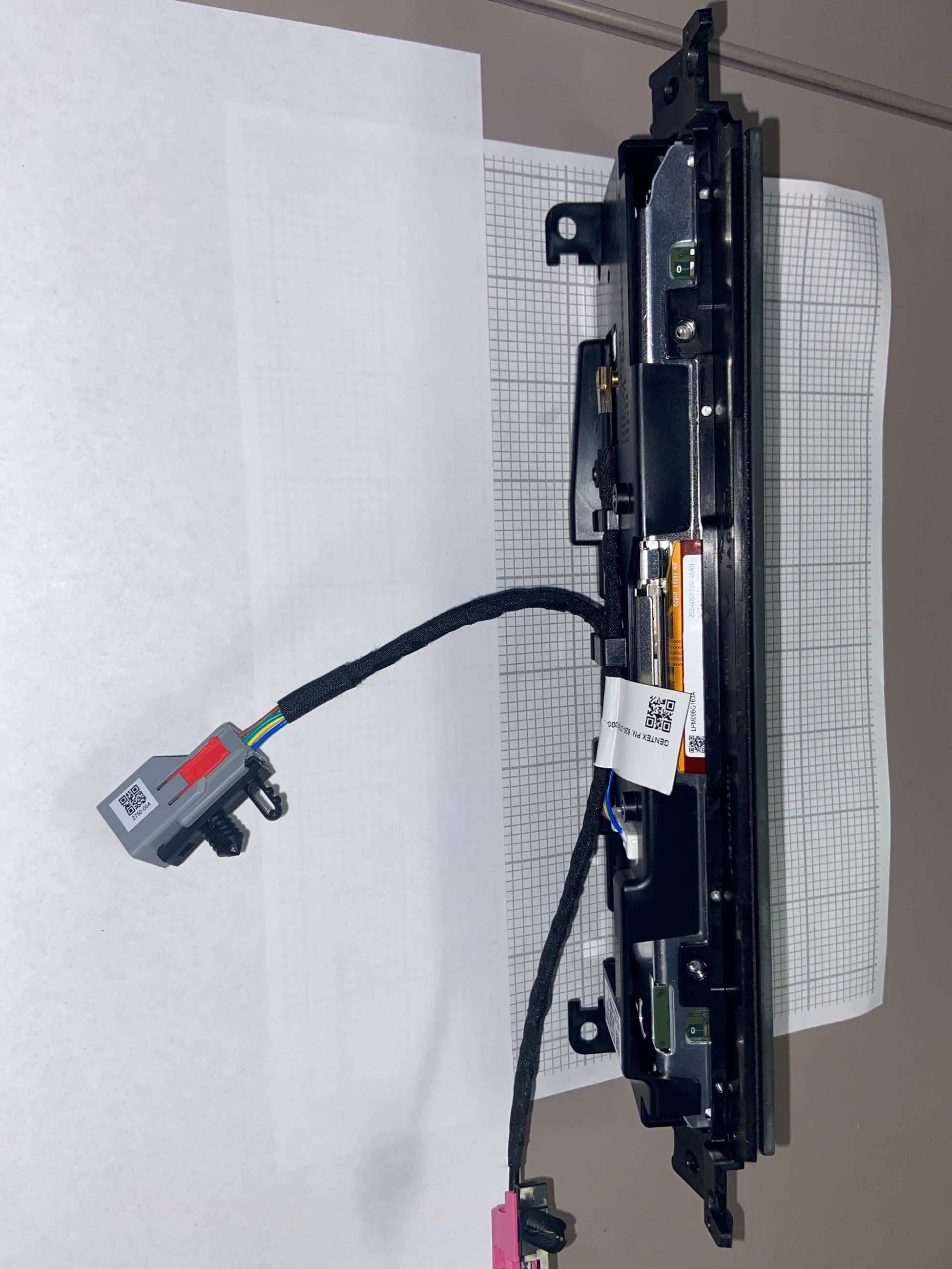
NZLRDHL6A
Jul 29, 2026Wireless Garage Door Opener
Equipment Class
CYY - Communications Receiver used w/Pt 15 Transmitter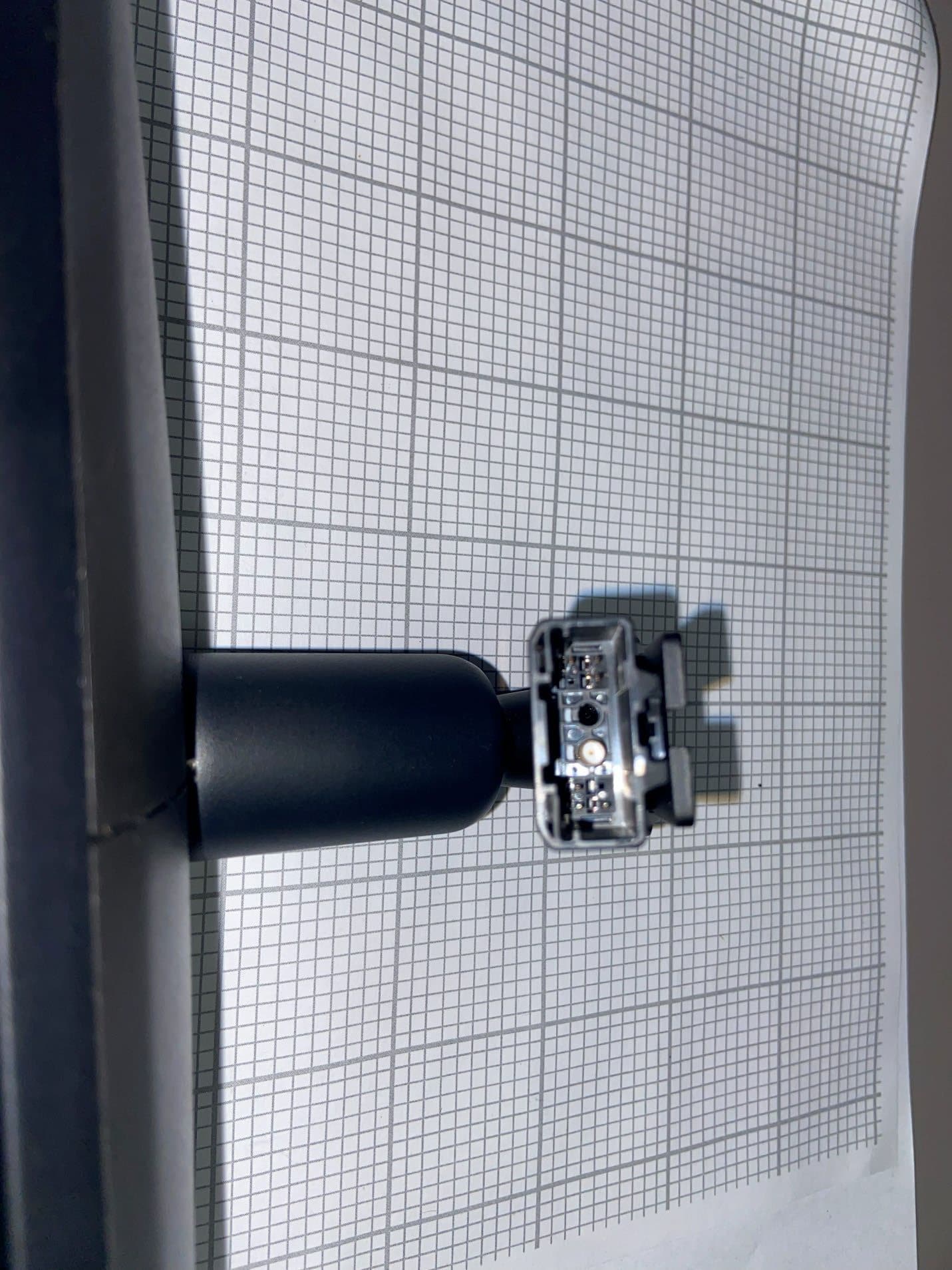
NZLFDMHL6D
Jun 15, 2026Wireless Garage Door Opener
Equipment Class
DTS - Digital Transmission System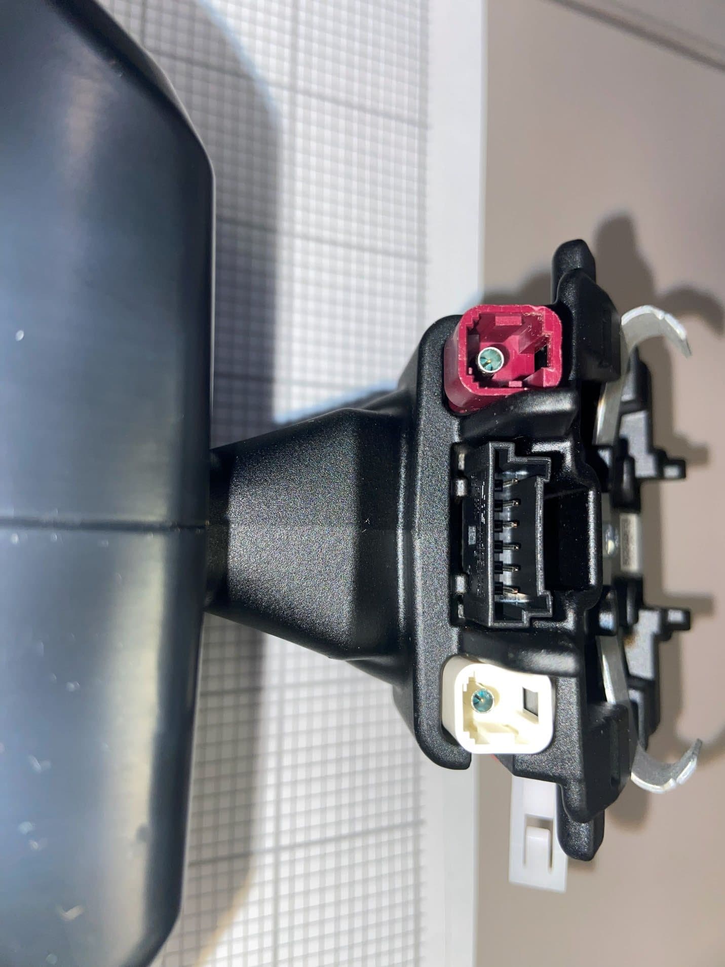
NZLFDMHL6B
May 18, 2026Wireless Garage Door Opener
Equipment Class
DSS - Part 15 Spread Spectrum Transmitter
NZLDEFRX6
May 04, 2026Default Receiver
Equipment Class
DTS - Digital Transmission System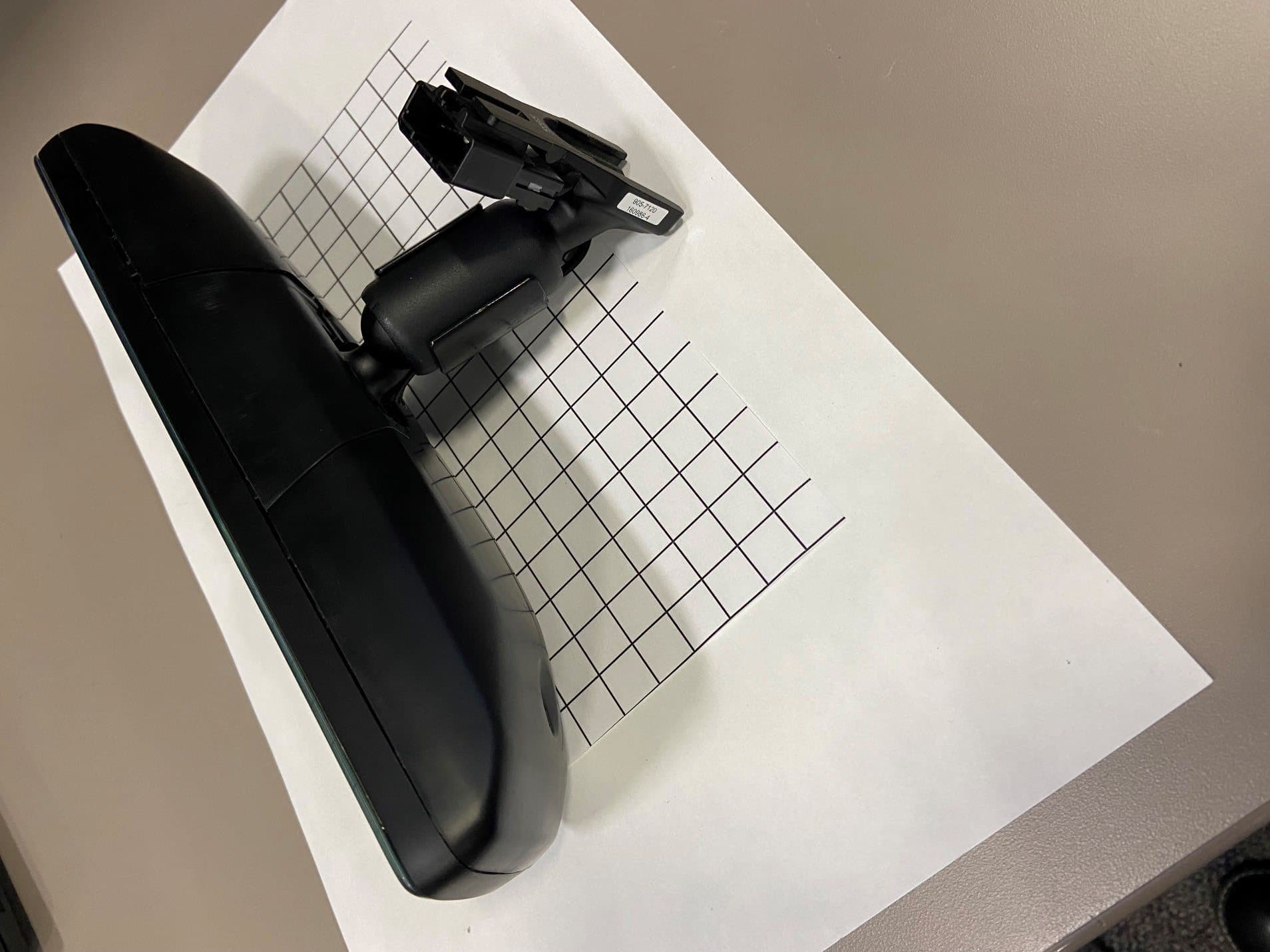
NZLFDMHL6A
Jan 12, 2026Wireless Garage Door Opener
Equipment Class
DTS - Digital Transmission System