NZLUAHL5KWireless Garage Door Opener
Gentex Corporation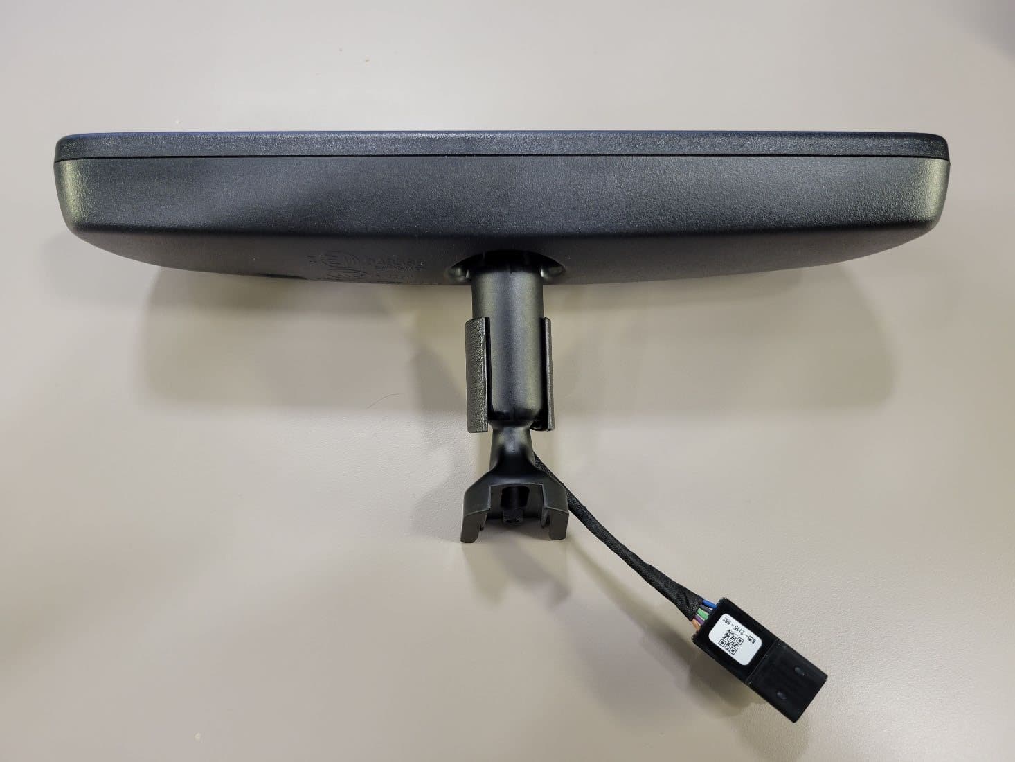
Click to zoom
Application Details
- Equipment Class
- CYY - Communications Receiver used w/Pt 15 Transmitter
- Date of Grant
- Feb 24, 2022
- Application Purpose
- Original Equipment
- Date of Application
- Feb 14, 2022
- Equipment Note
- Wireless Garage Door Opener
- Frequency Range
- 902.25000000 - 926.75000000
- Company
- Gentex Corporation
- Country
- United States
Documents & Files
Document Text
Text extracted from the exhibit documents filed with the FCC. Open a document above to read the original.
Users Manual
HomeLink and the HomeLink house are registered trademarks of Gentex Corporation. Programming and Information Guide The following is suggested text to be included in the vehicle Owner’s Manual, to assist the End User with functionality of their HomeLink Device. Italicized text is not intended to be part of the manual text, just provided for clarification only. The HomeLink Wireless Control System provides a convenient way to replace up to three hand- held radio-frequency (RF) transmitters used to activate devices such as gate operators, garage door openers, entry door locks, security systems, even home lighting. Additional HomeLink information can be found at www.HomeLink.com , www.youtube.com/HomeLinkGentex, or by calling the toll-free HomeLink-Hotline at 1-800-355-3515 (North America), (0) 0800 046 635 465 (Europe), +49 6838 907 277 (Europe, subject to charge). Before Programming HomeLink During programming, it is possible that garage doors, gates, or other devices may operate. For this reason, make sure that people and objects are clear of the garage door or other devices to prevent injury or other potential harm. Do not use HomeLink with any garage door opener that lacks safety stop and reverse features as required by U.S. federal safety standards (this includes any garage door opener model manufactured before April 1, 1982). A garage door that cannot detect an object - signaling the door to stop and reverse - does not meet current U.S. federal safety standards. It i s recommended that a new battery be placed in the remote control transmitter for more accurate programming. Garage door opener motors manufactured after 1995 may be equipped with rolling code protection. If this is the case, you may need a stepladder or other sturdy, safe device to reach the “Learn” or “Smart” button on the garage door motor. Retain the original transmitter of the RF device you are programming for use in other vehicles as well as for future HomeLink programming. It is suggested that upon the sale or lease termination of the vehicle, the programmed HomeLink buttons be erased for security purposes. Refer to “Erasing HomeLink Buttons” later in these instructions. You can program a maximum of three devices. To change or replace any of the three devices after it has been initially programmed, you must first erase the current settings. See ‘Erasing HomeLink Buttons’ or ‘Reprogramming a Single HomeLink Button’ later in these instructions. Please note that the instructions below apply to the majority of HomeLink use cases. However, there are some HomeLink applications or HomeLink compatible systems that require slightly different instructions. HomeLink and the HomeLink house are registered trademarks of Gentex Corporation. Programming a New HomeLink Note: Some vehicles may require the ignition switch to be turned on or to the second (“accessories”) position for programming and/or operation of HomeLink. It is also recommended that a new battery be placed in the hand-held transmitter of the device being programmed to HomeLink for quicker training and accurate transmission of the radio-frequency signal. 1. Press the HomeLink button that you would like to program. The indicator light will flash orange slowly (if not, refer to “Erasing HomeLink Buttons” later in these instructions). You do not need to continue holding the HomeLink button. 2. Position the end of your hand-held transmitter 1–3 inches (2–8 cm) away from the HomeLink button while keeping the indicator light in view. Note: Some hand-held transmitters may actually train better a distance of 6-12 inches (15-20 cm). Keep this in mind if you have difficulty with the Programming Process. 3. Press and hold the hand-held transmitter button while watching the indicator light on HomeLink. Continue pressing the button until the HomeLink indicator light changes from slowly flashing orange to either rapidly flashing green (rolling code) or continuously lit (fixed code) green. Now you may release the hand-held transmitter button. Note: Some devices may require you to replace this “Programming a New HomeLink” step 3 with procedures noted in the “Gate Operator / Canadian / European Programming” section. If the HomeLink indicator light does not change to rapidly flashing green or continuously lit green after performing these steps, contact HomeLink at www.HomeLink.com 4. Press the just-trained HomeLink button and observe the indicator light. • If the indicator light stays on constantly green, programming is complete and your device should operate when the HomeLink button is pressed and released. • If the indicator light rapidly flashes green, firmly press, hold for two seconds and release the programmed HomeLink button. Repeat the "press/hold/release" sequence a second time, and, depending on the brand of the garage door opener (or other rolling code equipped device), repeat this sequence a third time to complete the programming process. At this point if your device operates, programming is complete. • If the device does not operate, continue with “Programming a New HomeLink” steps 5-7 to complete the programming of a rolling code equipped device. 5. At the garage door opener receiver (motor-head unit) in the garage, locate the “Learn” or “Smart” Button. This can usually be found where the hanging antenna wire is attached to the motor-head unit (see the Garage Door Opener manual to identify the “Learn Button”). HomeLink and the HomeLink house are registered trademarks of Gentex Corporation. Figure 1: Approximate Learn Button Location 6. Firmly press and release the “Learn” or “Smart” button. (The name and color of the button may vary by manufacturer.) There are typically 30 seconds to initiate step 7. 7. Return to the vehicle and firmly press, hold for two seconds and release the programmed HomeLink button. Repeat the “press/hold/release” sequence a second time, and, depending on the brand of the garage door opener (or other rolling code equipped device), repeat this sequ…
Text truncated - open the document above for the full version.
External Photos
UAHL5K UAHL5K UAHL5K UAHL5K UAHL5K
ID Label/Location Info
Label Location
Internal Photos
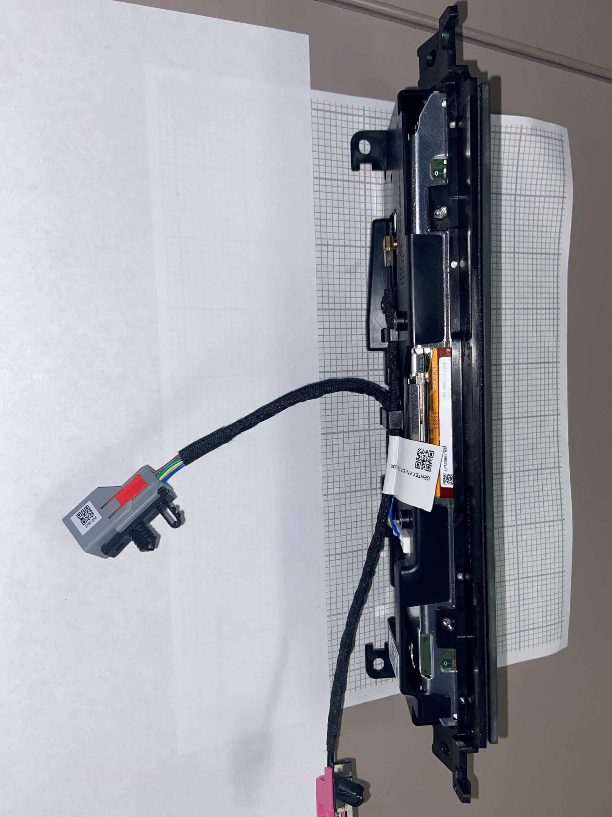
UAHL5K – Internal Photos UAHL5K – Internal Photos UAHL5K – Internal Photos UAHL5K – Internal Photos UAHL5K – Internal Photos Trace Antenna TX Area
Test Report
Lab Project ID#: EMC2021-07104 Test ID: Test-079918 Model: UAHL5K FCC Report Form for Part 15 Class B Emissions Date: 2/2/22 Revision: 12/06/2021 Approved By: Craig Harder Page 1 of 8 Uncontrolled copy if printed unless stamped as a Lab Controlled Document Technical Report to the FCC Gentex Corporation Model: UAHL5K FCC ID: NZLUAHL5K ISED: 4112A-UAHL5K 2/2/22 A report concerning approval for Gentex Corporation model UAHL5K Please issue grant immediately upon review. Measurements Made by: Measurements Reviewed by: Bolay Pannell Dan Brasier Laboratory Validation Engineer III Laboratory Development Engineer II Gentex Corporation Gentex Corporation Report Approved, Prepared, and Submitted by: Brian Miller Laboratory Group Leader – Regulatory II Gentex Corporation Lab Project ID#: EMC2021-07104 Test ID: Test-079918 Model: UAHL5K FCC Report Form for Part 15 Class B Emissions Date: 2/2/22 Revision: 12/06/2021 Approved By: Craig Harder Page 2 of 8 Uncontrolled copy if printed unless stamped as a Lab Controlled Document Test Report Revision REV Number Date Author Description 1.0 2/2/22 Brian Miller Initial Release. Results relate only to the items tested as received. Compliance has been evaluated based on the Lab Manual section 7.6.2. The decision rule used regarding measurement uncertainty was to determine results solely on whether the measured values met the defined acceptance criteria without factoring in measurement uncertainty values. Lab Project ID#: EMC2021-07104 Test ID: Test-079918 Model: UAHL5K FCC Report Form for Part 15 Class B Emissions Date: 2/2/22 Revision: 12/06/2021 Approved By: Craig Harder Page 3 of 8 Uncontrolled copy if printed unless stamped as a Lab Controlled Document 1. General Information 1.1. Product Description The Gentex Corporation HomeLink OEM device that is installed into the rearview mirror. The installation is provided by trained technicians during the manufacture of the automobile. It is powered by the 12 Volt system of the automobile. The unit is supplied to the automobile manufacturer without harness. For testing purposes, a typical assembly and 2-conductor cable harness were used to power to the unit. The antenna system is an integral part of the unit. It cannot be altered nor replaced by the user. Service of this system is only available from the Automobile Manufacturer’s Dealerships and Gentex Corporation. 1.2. Related Grants This device will have functionality that is covered under 47 CFR Part 15.231 and 15.247 and ISED Canada RSS-210 and RSS-247. The device will have FCC ID # of NZLUAHL5K and ISED ID # of 4112A-UAHL5K. 1.3. Test Methodology Radiated Emissions testing was performed according to ANSI C63.4:2014. The power source for this product is a 12V automotive vehicle battery, thus conducted emissions measurements are not required. The DUT was tested by placing it in RX mode with a signal generator transmitting to a loop antenna within proximity of the DUT. The emissions sweeps were performed with the signal generator transmitting a CW signal at the low, mid, and high frequency of the intentional radiator frequency bands. The unit is supplied to the automobile manufacturer without harness. For testing purposes a 2- conductor cable harness was used to interface to the unit. The DUT was tested in receive mode only. 1.4. Test Facility The 3-meter semi-anechoic chamber where these measurements were taken is located on the grounds of Gentex Corporation’s Corporate Labs, in the city of Zeeland, county of Ottawa, state of Michigan, United States of America. For radiated measurements above 1 GHz, RF absorbing material is placed between the antenna and EUT in accordance with ANSI C63.4:2014 Section 5.5 and chamber manufacturer’s instructions. Tabletop testing was conducted on a 3m turntable described in the site recertification report. The 3m chamber has been added to our A2LA scope of accreditation on 4/18/2019 and includes accreditation to ANSI C63.4:2014, ANSI C63.10:2013, and C63.26:2015. Our 3m chamber is registered with the ISED under Site# 4112A-2 and FCC under registration number 357351. Lab Project ID#: EMC2021-07104 Test ID: Test-079918 Model: UAHL5K FCC Report Form for Part 15 Class B Emissions Date: 2/2/22 Revision: 12/06/2021 Approved By: Craig Harder Page 4 of 8 Uncontrolled copy if printed unless stamped as a Lab Controlled Document Corporate Mailing/Shipping Address Gentex Corporation 600 N. Centennial Street Zeeland, MI 49464 Site Address Gentex Corporation 380 Riley Street Zeeland, MI 49464 1.5. Accreditation The Gentex Corporate EMC Lab is accredited to ISO/IEC 17025 by the American Association for Laboratory Accreditation (A2LA). Our laboratory scope and accreditation certificate #2529.01 are available from their web site www.a2la.org. Our scope of accreditation covers ANSI C63.4:2014, ANSI C63.10:2013, ANSI C63.26:2015 and Radiated Emissions at 3m, FCC 47 CFR Part 90, ISED RSS-137. 2. Product Labeling 2.1. Identifiers The FCC Identifier assigned is FCC ID: NZLUAHL5K. The ISED certification number is 4112A- UAHL5K. These identifiers will be labeled on the product housing. The label will be printed on a label, which will be placed on the exterior of the housing and permanently affixed. Because of the small size of the device and because the installation is inside a portion of the automobile, the following statements will appear in the user’s manual. Refer to attachment “Users Manual.pdf” for the entire text of the user’s manual. “The receiver portion of the device complies with FCC rule Part 15. Operation is subject to the following two conditions: (1) This device may not cause harmful interference, (2) This device must accept any interference that may be received including interference that may cause undesired operation. WARNING: The transmitter has been tested and complies with FCC and ISED rules. Changes or modifications not expressly approved by the party responsible for the compliance could void the user’s authority to operate the device…
Text truncated - open the document above for the full version.
Test Setup Photos
Test Setup Photos Test Setup – Bicon Test Setup Photos Test Setup – Log Test Setup Photos Test Setup – Horn Test Setup Photos Test Setup – End Orientation Test Setup Photos Test Setup – Flat Orientation Test Setup Photos Test Setup – Side Orientation
Contact Information
Applicant
Brian Miller(Corporate Labs Group Leader - Wireless Regulatory)
Technical Contact
Non-Technical Contact
Gentex CorporationJason Vargo
[email protected]6167721800
Test Firm
Gentex CorporationBrian Miller
Technical Specifications
| # | Rule Parts | Frequency Range | Power Output |
|---|---|---|---|
| 5 | 15B | 902.25 MHz - 926.75 MHz | - |
Other Applications from Gentex Corporation
NZLRDHL6A
Jul 29, 2026Wireless Garage Door Opener
Equipment Class
CYY - Communications Receiver used w/Pt 15 Transmitter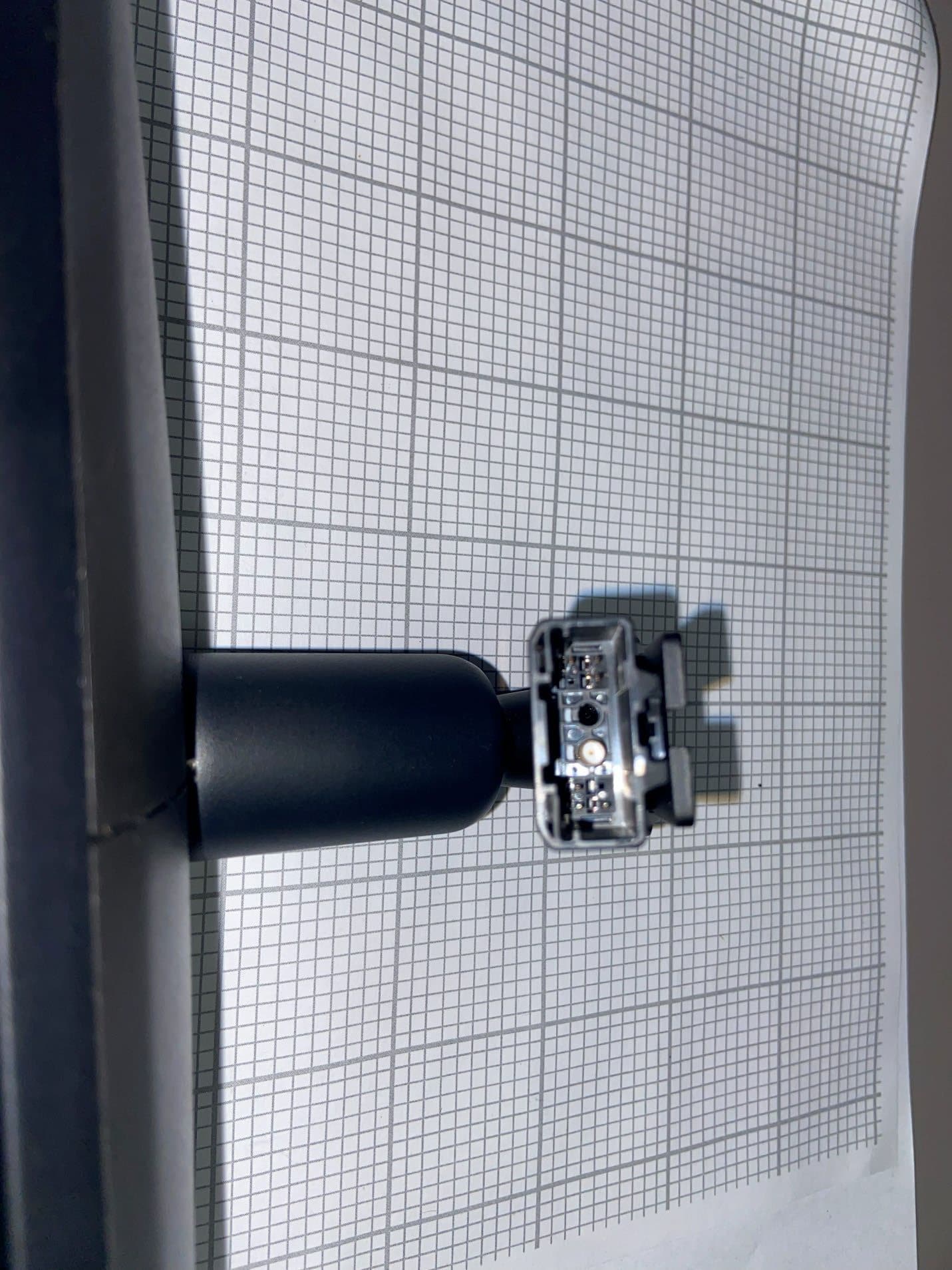
NZLFDMHL6D
Jun 15, 2026Wireless Garage Door Opener
Equipment Class
DTS - Digital Transmission System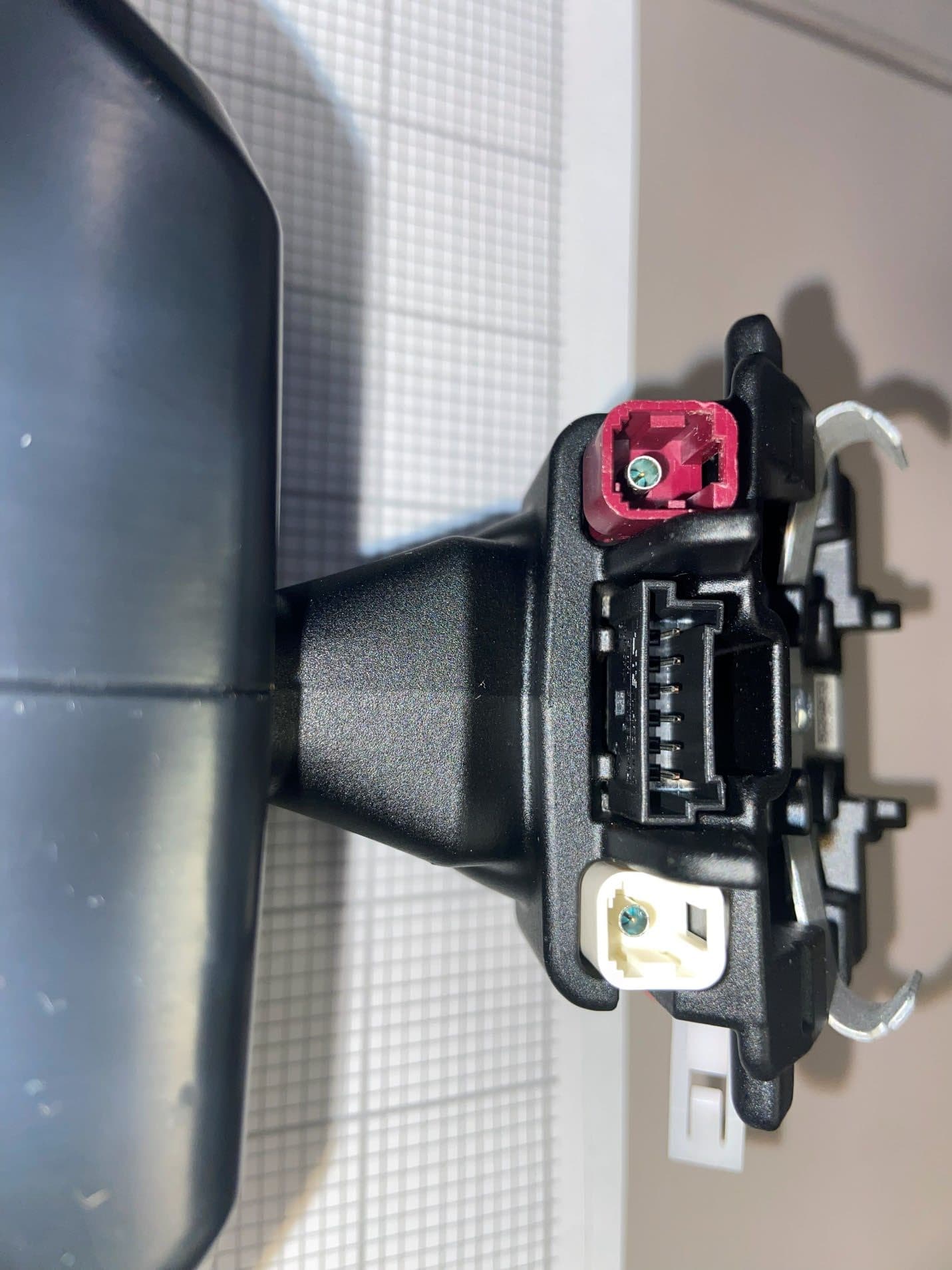
NZLFDMHL6B
May 18, 2026Wireless Garage Door Opener
Equipment Class
DSS - Part 15 Spread Spectrum Transmitter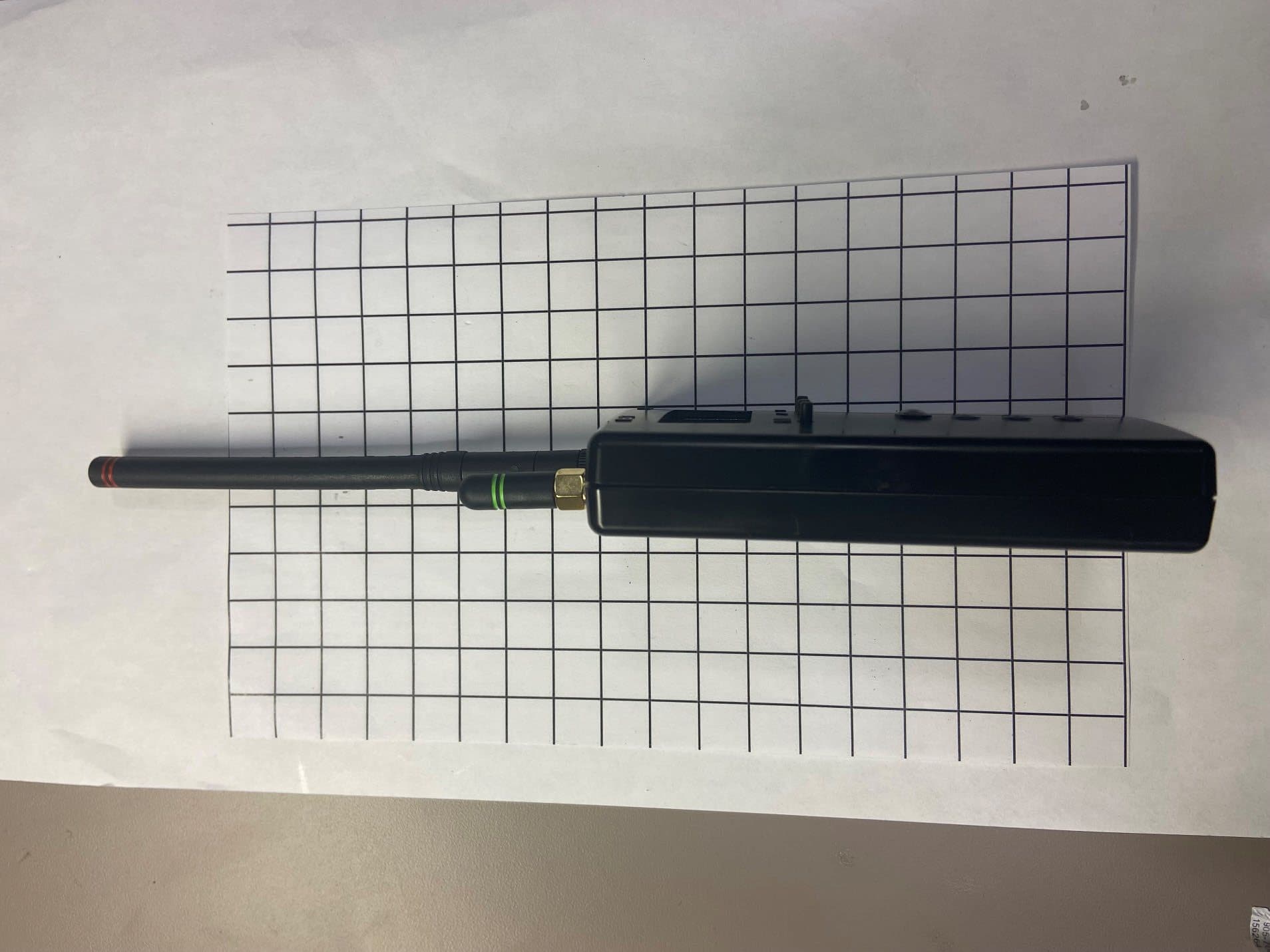
NZLDEFRX6
May 04, 2026Default Receiver
Equipment Class
DTS - Digital Transmission System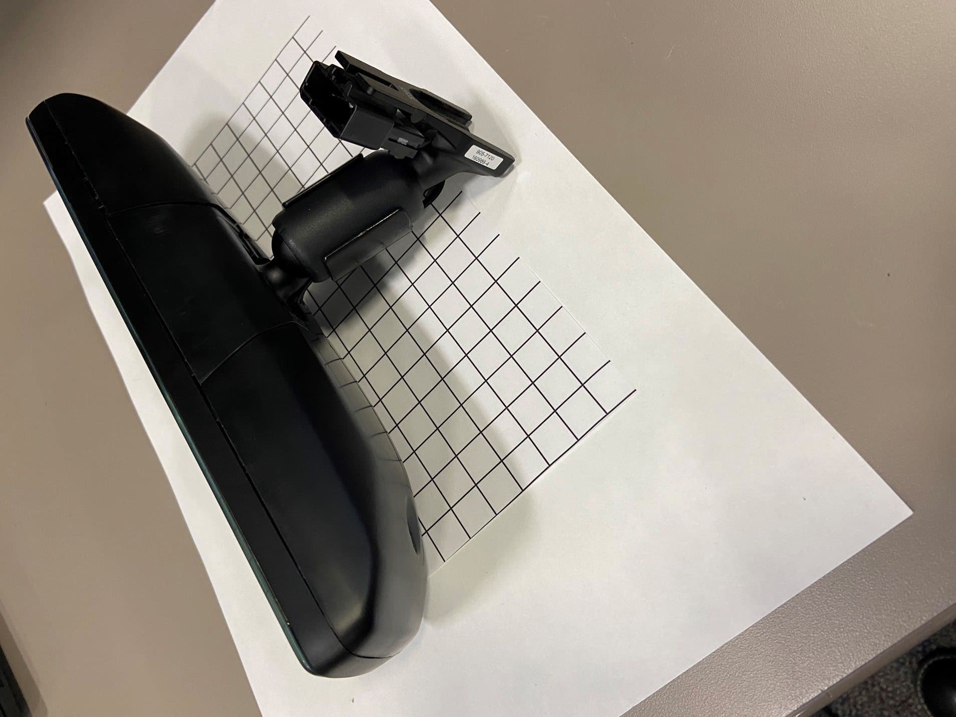
NZLFDMHL6A
Jan 12, 2026Wireless Garage Door Opener
Equipment Class
DTS - Digital Transmission System