O2J-070T700 MHz SCRT
Airspan Communications Limited
Click to zoom
Application Details
- Equipment Class
- TNB - Licensed Non-Broadcast Station Transmitter
- Date of Grant
- May 05, 2010
- Application Purpose
- Original Equipment
- Date of Application
- Apr 28, 2010
- Equipment Note
- 700 MHz SCRT
- Frequency Range
- 704.00000000 - 740.00000000
- Country
- United Kingdom
Documents & Files
Document Text
Text extracted from the exhibit documents filed with the FCC. Open a document above to read the original.
Cover Letter(s)
Sulis Consultants Limited Mead House, Longwater Road, Eversley, Hampshire, RG27 0NW, UK Registered in England & Wales, number 05466247 http://www.sulisconsultants.com 26 th April 2010 Federal Communications Commission Office of Engineering and Technology Equipment Authorization Division 7345 Oakland Mills Road Columbia, Maryland 21046 Subject: Permanent Confidentiality request for FCC ID:O2J-070T To whom it may concern Pursuant to sections 0.457 and 0.459 and CFR 47, the applicant requests permanent confidential treatment of the following information accompanying this application: Schematics:sch_303-1204-100_revA0.pdf Parts List:303_1204_900_revB0_Parts_List.pdf Block Diagram:700MHz_TDD_SCRT_block_diagram_v1.pdf The above materials contain trade secrets and proprietary information not customarily released to the public. The public disclosure of these matters might be harmful to the applicant and provide unjustified benefits to its competitors Yours Sincerely Charlie Blackham Director
Cover Letter(s)
Airspan Communications Ltd.MicroMAX SDR + SCRT FCC Test Plan Doc. Ref: 005-8300-012Page 4 of 8 Rev. draft14February 2006 3Responsible Party The responsible party, according to 2.909 is the manufacturer or the importer. However, 2.1077 (3) states that the responsible party for a Declaration of Conformity shall be located in the USA. Therefore an employee of Airspan Networks, Inc. shall sign FCC Declarations of Conformity. For all other purposes, Airspan Communications Limited shall be deemed the responsible party. 4Route to Conformity According to 15.101 for unintentional transmitters and 15.201 for intentional transmitters, the routes for conformity are as follows: ProductRouteReason SCRTCertification by the Commission or TCB It is an intentional transmitter SDRVerification Or Certification It is a Class A unintentional transmitter Or It is part of an intentional transmitter 4.1SCRT Testing is required 4.2SDR To be discussed. Baseband RF signal originates on SDR and arrives on SCRT as an I/Q stream. 4.3Electromagnetic Exposure Airspan have written a report, 005-8390-00_C, demonstrating compliance with the human exposure requirements detailed in EN50385:2002 – this should suffice for the FCC requirements. Airspan Communications Ltd.MicroMAX SDR + SCRT FCC Test Plan Doc. Ref: 005-8300-012Page 5 of 8 Rev. draft14February 2006 5System Configuration MicroMAX-SDR is an IEEE802.16-2004 WiMAX basestationdesigned to be located on utility poles or roof tops providing point to multi-point WiMAX coverage from an all outdoor base station over micro-cellular 1 ranges to various CPE types. SDR – Software defined Radio base-unit contains mains to dc power supply tosupply dc power to the 1179 digital card within the SDR and 48V DC to power the external SCRTs. This unit does notoperate as a software defined radio as defined by Report and Order (FCC 05-57): FCC 05-57 defines “Software Defined Radio” as: A radio that includes a transmitter in which the operating parameters of frequency range, modulation type or maximum output power (either radiated or conducted), or the circumstances under which the transmitter operates in accordance with Commission rules, can be altered by making a change in software without making any changes to hardware components that affect the radio frequency emissions. It goes on to say: We find that the rules we are adopting that require the certification of certain radios as software definedradios will not be unduly burdensome on manufacturers or restrain the development of technology. Only a relatively small number of radios will be affected by this requirement because most RF affecting radio software is not designed or expected to be modified by a party other than the manufacturer, and we are not changing the rules for radios that are not designed or expected to be modified by a party other than the manufacturer. Thus, there will be no change to the authorization requirement for the vast majority of devices including cellular/PCS telephones, land mobile transceivers and Wi-Fi equipment, provided the software that directly or indirectly controls the RF emissions of these devices is not designed or expected to be modified by a party other thanthe manufacturer. Also, manufacturers of radios that are software modifiable typically already take steps to prevent unauthorized modifications to the software in a radio, so we expect that only rarely will manufacturers have to make significant design changes to comply with the security requirements. The SDR usesPicochipFPGAs that are designed to allow future upgrade from 802.16-2004 WiMAX to 802.16e, and any future upgrade would be fully under the control of the manufacturer. . A MicroMAX-SDR Base Station consists of the following components: 1xSoftware Defined Radio (SDR) (including SDR boards plus PSU for SDR + SCRTs) 1x or 2xSingleChannel RF Transceiver (SCRT) 1x or 2xAntenna (customer supplied) 1 Micro-cell implies micro RF coverage due to expected base station and CPE deployment types. Ie. Low sited base stations serving indoor CPE.
External Photos
81.90 416 84 AIRSPAN SCRT ASSEMBLY SHOWN WITH SUN SHIELD FITTED 2 NOVEMBER 2005 B Lyford 333 127 113 72.80 195 163.80 145.6 71 297 182
ID Label/Location Info
SCRT label and position FCC ID: O2J-070T SCRT-1-700T-USL
Parts List/Tune Up Info
Transmit power is set using the “TX Power (Custom) box” in the Netspan management software.The management software limits the maximum power to 36 dBm, but allows lower levels to be set by the operator. An example Netspan SCRT screenshot is shown below
RF Exposure Info
Sulis Consultants Limited Mead House, Longwater Road, Eversley, Hampshire, RG27 0NW, UK Registered in England & Wales, number 05466247 http://www.sulisconsultants.com Airspan 700 MHz SCRT (FCC ID:O2J-070T) Maximum Permitted Exposure Calculation O2J-070T_MPE_calc The equation for the MPE calculation is given in OET bulletin 65, page 19 as S = EIRP/4πr 2 WhereS = Power density (W/m 2 ) EIRP= Effective Isotropically Radiated Power= P x G (W) r = Perpendicular distance from antenna The 700 MHz SCRT operates with a maximum antenna port power of 36dBm, a maximum permitted antenna gain of 14.5 dBi, and a minimum recommended safe distance of 1.5 m. ValuesP = 36dBm= 3981 mW G =14.5dBi= 28.2linear R= 65cm LimitMaximum permitted value of S is given in table 1(a) – Limits for occupational/ controlled Exposurein frequency range 300-1500 MHz is given by: S permitted = f (MHz)/300 = 2.327mW/cm 2 at 698MHz = 2.487mW/cm 2 at 746 MHz CalculationS = 3981* 28.2/ (4 * 3.14159 * 65 2 ) S = 2.113 mW/cm 2 ConclusionThe Airspan 700 MHz SCRT meets the requirements at a distance of 65cm from the antenna.
Test Report
Sulis Consultants Limited Mead House, Longwater Road, Eversley, Hampshire, RG27 0NW, UK Registered in England & Wales, number 05466247 http://www.sulisconsultants.com RFTest Report: Airspan 700 MHz SCRT SC_TR02_A Prepared for: Airspan Communications Ltd Cambridge House Oxford Road Uxbridge UB8 1UN Circulation:Airspan Communications Ltd Sulis Consultants Ltd SC_TR02_APage 2 of 46 Contents 1Revision History5 2Purpose5 3Reference Documents5 4Product Description6 5Tests performed7 6Test Configuration8 6.1Test sample and Operating mode8 6.2Support equipment8 6.3Test equipment8 6.4Equipment set-up9 7Occupied Bandwidth: 47CFR2.104910 8Transmit Power density 47CFR27.50(c)(3)18 9Transmit Burst Power25 10Conducted Band Edge – 47CFR27.53(g)32 11Conducted Spurious Emissions – 47CFR27.53(g)41 12Test Plan SC_AIR_TP01_A46 Tables Table 1: Summary of tests performed...........................................................................7 Table 2: Equipment under test.....................................................................................8 Table 3: Support Equipment.........................................................................................8 Table 4: Test Equipment..............................................................................................8 Table 5: Occupied Bandwidth test results.....................................................................10 Table 6: Transmit Power Density test results................................................................18 Table 7: Transmit Power Density test results................................................................25 Table 8: Conducted Band Edge Emissions....................................................................32 Table 9: Conducted spurious emissions 30MHz – 679.9 MHz..........................................41 Table 10: Conducted Spurious emissions 746.1 – 7500 MHz...........................................41 Table 11: Summary of tests to be performed at RFI......................................................46 SC_TR02_APage 3 of 46 Figures Figure 1: LI Probe test configuration: Emissions.............................................................9 Figure 2: Occupied Bandwidth, 5MHz, 701.0 MHz, BPSK ½ ............................................11 Figure 3: Occupied Bandwidth, 5MHz, 701.0 MHz, QPSK ¾ ............................................11 Figure 4: Occupied Bandwidth, 5MHz, 701.0 MHz, 16QAM ¾ .........................................12 Figure 5: Occupied Bandwidth, 5MHz, 701.0 MHz, 64 QAM ¾ .........................................12 Figure 6: Occupied Bandwidth, 5MHz, 719.0 MHz, QPSK ¾ ............................................13 Figure 7: Occupied Bandwidth, 5MHz, 719.0 MHz, 64 QAM ¾ .........................................13 Figure 8: Occupied Bandwidth, 5MHz, 743.0 MHz, 64 QAM ¾ .........................................14 Figure 9: Occupied Bandwidth, 10MHz, 704.0 MHz, BPSK ½...........................................14 Figure 10: Occupied Bandwidth, 10MHz, 704.0 MHz, QPSK ¾.........................................15 Figure 11: Occupied Bandwidth, 10MHz, 704.0 MHz, 16 QAM ¾ .....................................15 Figure 12: Occupied Bandwidth, 10MHz, 704.0 MHz, 64 QAM ¾ .....................................16 Figure 13: Occupied Bandwidth, 10MHz, 722.0 MHz, QPSK ¾.........................................16 Figure 14: Occupied Bandwidth, 10MHz, 722.0 MHz, 16 QAM ¾ .....................................17 Figure 15: Occupied Bandwidth, 10MHz, 740.0 MHz, 16 QAM ¾ .....................................17 Figure 16: TX power density, 5MHz, 701.0 MHz, BPSK ½ ...............................................19 Figure 17: TX power density, 5MHz, 701.0 MHz, QPSK ¾...............................................19 Figure 18: TX power density, 5MHz, 701.0 MHz, 16 QAM ¾ ...........................................20 Figure 19: TX power density, 5MHz, 701.0 MHz, 64 QAM ¾ ...........................................20 Figure 20: TX power density, 5MHz, 719.0 MHz, 16 QAM ¾ ...........................................21 Figure 21: TX power density, 5MHz, 743.0 MHz, 16 QAM ¾ ...........................................21 Figure 22: TX power density, 10MHz, 704.0 MHz, BPSK ½ .............................................22 Figure 23: TX power density, 10MHz, 704.0 MHz, QPSK ¾.............................................22 Figure 24: TX power density, 10MHz, 704.0 MHz, 16 QAM ¾..........................................23 Figure 25: TX power density, 10MHz, 704.0 MHz, 64 QAM ¾..........................................23 Figure 26: TX power density, 10MHz, 704.0 MHz, QPSK ¾.............................................24 Figure 27: TX power density, 10MHz, 704.0 MHz, QPSK ¾.............................................24 Figure 28: TX burst power, 5MHz, 701.0 MHz, BPSK ½..................................................26 Figure 29: TX Burst Power, 5MHz, 701.0 MHz, QPSK ¾ .................................................26 Figure 30: TX Burst Power, 5MHz, 701.0 MHz, 16QAM ¾ ..............................................27 Figure 31: TX Burst Power, 5MHz, 701.0 MHz, 64 QAM ¾ ..............................................27 Figure 32: TX Burst Power, 5MHz, 719.0 MHz, QPSK ¾ .................................................28 Figure 33: TX Burst Power, 5MHz, 743.0 MHz, QPSK ¾ .................................................28 Figure 34: TX Burst Power, 10MHz, 704.0 MHz, BPSK ½................................................29 Figure 35: TX Burst Power, 10MHz, 704.0 MHz, QPSK ¾................................................29 Figure 36: TX Burst Power, 10MHz, 704.0 MHz, 16 QAM ¾ ............................................30 Figure 37: TX Burst Power, 10MHz, 704.0 MHz, 64 QAM ¾ ............................................30 Figure 38: TX Burst Power, 10MHz, 722.0 MHz, QPSK ¾................................................31 Figure 39: TX Burst Power, 10MHz, 740.0 MHz, QPSK ¾.......................................…
Text truncated - open the document above for the full version.
Test Report
TEST REPORT FROM RFI GLOBAL SERVICES LTD Test of: SCRT-1-700T To: FCC Part 27: 2009 Subpart C in accordance with Test Plan SC_AIR_TP01_A dated 14th April 2010 Test Report Serial No: RFI/RPT1/RP77581JD01A This Test Report Is Issued Under The Authority Of Brian Watson, COO Payments and Consultancy: Checked By: Nigel Davison Signature: Date of Issue: 21 April 2010 This report is issued in Adobe Acrobat portable document format (PDF). It is only a valid copy of the report if it is being viewed in PDF format with the following security options not allowed: Changing the document, Selecting text and graphics, Adding or changing notes and form fields. This report may not be reproduced other than in full, except with the prior written approval of RFI Global Services Ltd. The results in this report apply only to the sample(s) tested. TEST REPORT SERIAL NO: RFI/RPT1/RP77581JD01A ISSUE DATE: 21 APRIL 2010 Page 2 of 39 RFI Global Services Ltd This page has been left intentionally blank. TEST REPORT SERIAL NO: RFI/RPT1/RP77581JD01A ISSUE DATE: 21 APRIL 2010 RFI Global Services Ltd Page 3 of 39 Table of Contents 1. Customer Information .................................................................................................................. 4 2. Summary of Testing ..................................................................................................................... 5 3. Equipment Under Test (EUT) ....................................................................................................... 7 4. Operation and Monitoring of the EUT during Testing ............................................................. 10 5. Measurements, Examinations and Derived Results ................................................................ 11 6. Measurement Uncertainty .......................................................................................................... 38 Appendix 1. Test Equipment Used ................................................................................................39 TEST REPORT SERIAL NO: RFI/RPT1/RP77581JD01A ISSUE DATE: 21 APRIL 2010 Page 4 of 39 RFI Global Services Ltd 1. Customer Information Company Name: Airspan Communications Ltd Address: Cambridge House Oxford Road Uxbridge Middlesex UB8 1UN United Kingdom TEST REPORT SERIAL NO: RFI/RPT1/RP77581JD01A ISSUE DATE: 21 APRIL 2010 RFI Global Services Ltd Page 5 of 39 2. Summary of Testing 2.1. General Information Specification Reference: 47CFR27 Specification Title: Code of Federal Regulations Volume 47 (Telecommunications) 2009: Part 27 Subpart C (Miscellaneous Wireless Communication Services) Site Registration: FCC: 209735 Location of Testing: RFI Global Services Ltd, Wade Road, Basingstoke, Hampshire, RG24 8AH. Test Dates: 14 April 2010 to 16 April 2010 2.2. Summary of Test Results FCC Reference (47CFR) Measurement Result FCC Part 15.207 Transmitter AC Conducted Spurious Emissions FCC Part 2.1046 FCC Part 27.50(c) Transmitter Carrier Output Power and Effective Radiated Power (ERP) FCC Part 2.1049 Transmitter Occupied Bandwidth FCC Part 2.1051 FCC Part 27.53(g) Transmitter Band Edge Conducted Emissions FCC Part 2.1051 FCC Part 27.53(g) Transmitter Conducted Emissions FCC Part 2.1051 FCC Part 27.53 Transmitter Radiated Spurious Emissions FCC Part 2.1055 FCC Part 27.54 Transmitter Frequency Stability Key to Results = Complied = Did not comply TEST REPORT SERIAL NO: RFI/RPT1/RP77581JD01A ISSUE DATE: 21 APRIL 2010 Page 6 of 39 RFI Global Services Ltd 2.3. Methods and Procedures Reference: ANSI C63.4 (2003) Title: American National Standard Methods of Measurement of Electromagnetic Emissions from Low Voltage Electrical and Electronic Equipment in the Range of 9 kHz to 40 GHz. Reference: ANSI C63.10 (2009) Title: American National Standard Methods for Testing Unlicensed Wireless Devices Reference: ANSI/TIA-603-C-2004 Title: Land Mobile FM or PM - Communications Equipment - Measurement and Performance Standards 2.4. Deviations from the Test Specification Partial testing was performed in accordance with the customer’s test plan SC_AIR_TP01_A dated 14 th April 2010. Transmitter AC conducted emissions, peak power density, burst power, conducted band edge emissions, conducted spurious emissions, radiated spurious emissions and frequency stability tests were requested. TEST REPORT SERIAL NO: RFI/RPT1/RP77581JD01A ISSUE DATE: 21 APRIL 2010 RFI Global Services Ltd Page 7 of 39 3. Equipment Under Test (EUT) 3.1. Identification of Equipment Under Test (EUT) Description: 700 MHz TDD SCRT point-to-multipoint WiMAX base station Brand Name: Airspan Communication Model Name or Number: SCRT-1-700T Serial Number: T1204900T0A0101 Hardware Version Number: 605-0010-902 Software Version Number: _7_06_006 FCC ID Number: O2J-070T 3.2. Description of EUT The equipment under test was a point-to-multipoint WiMAX base station. 3.3. Modifications Incorporated in the EUT No modifications were applied to the EUT during testing. TEST REPORT SERIAL NO: RFI/RPT1/RP77581JD01A ISSUE DATE: 21 APRIL 2010 Page 8 of 39 RFI Global Services Ltd 3.4. Additional Information Related to Testing Tested Technology: WiMAX Category of Equipment: Fixed Type of Equipment Base station Intended Operating Environment: Commercial / Light Industrial Highest Internally Generated Clock or Oscillator Frequency: 746 MHz Modulation Type: Various, as specified in the Test Plan Duty Cycle 33 (%) in test mode Channel Spacing: Not stated Chip Rate: Not stated Declared Channel Bandwidth: 5 MHz and 10 MHz Antenna Connection Type: External Antenna Type: Various Antenna Gain: 14.5 dBi Nominal 48.0 V Minimum 40.8 V Power Supply Requirement: Maximum 55.2 V Minimum -30°C Tested Temperature Range: Maximum 50°C Transmit Frequency Range: 698 MHz to 746 MHz Channel Bandwidth (MHz) Bottom Channel frequency (MHz) Centre Channel Frequency (MHz) Top Channel Frequency (MHz) 5 701 719 743 Transmit Channel Description: 10 704 722 740 Receive Frequency Range: 698 MHz to 746 MHz Channe…
Text truncated - open the document above for the full version.
Test Report
Original comments by ATCB in black text. Applicant responses in red text. 1) Section 8 of the test report SC_TR02_A refers to power density. The EIRP is listed in dBm. For our records, please confirm that this unit should be dBm/MHz. EIRP listed in section 8 of SC_TR02_A should be dBm/MHz. 2) Section 9 of the test report SC_TR02_A shows the device to have a maximum output power of 35.5 dBm EIRP in 5 MHz channels and 35.4 dBm in 10 MHz channels. However, section 5.2.2 (page 23) of test report RFI/RP77581JD01A shows the device to have a maximum output power of 37.7 dBm in 5 MHz and 37.2 dBm in 10 MHz. This is only about 2 dB variation but it can have an effect on the reported power and on the certification of this device. For example, RFI’s output power of 37.7 dBm is above your tune up procedure’s maximum power of 36.0 dBm. Further to this, the maximum output power in the RFI test report is shown as 52.2 dBm ERP, which is 166 Watts. Your application form states a maximum power of 112.2 Watts. Please bear in mind that this could also affect your MPE calculation. • SC_TR02_A contains WiMAX “Burst Power” data – this is the power of the WiMAX data being transmitted and is the power level set by Netspan management software. This “burst power” can only be measured using specialised test equipment such as an FSQ8 with WiMAX option. The FSQ can extract accurate burst power measurement for any length of burst. • In accordance with FCC rules, RFI measured “Spectral Power” which includes the short duration WiMAX “pre-amble”. This pre-amble contain management information and is always transmitted at a higher level than the traffic. This is the level reported in test reports and used to demonstrate compliance with spectrum limits. • The power level measured using a power meter / spectrum analyser is always higher than that obtained when just measuring “burst power” with suitable equipment as the former includes the “pre-amble”. • The EUT is an FDD device. Power meters and Spectrum Analysers need to be given a duty cycle offset to allow them to report FDD power levels. The duty cycle for test was set at 33%, and an offset was used to then calculate the reported TX power, as noted on pages 15 and 16 of report RFI-RPT-RP77581JD01A. • In line with other FCC certifications of Airspan WiMAX basestations (FCC ID:O2J- SCRT-1-49T and FCC ID:O2J-365T) the stated transmit power is the Burst power which is the power level set by the Netspan management software and not the actual measured power. During normal operation, the base-station may be expected to operate with continually varying duty cycle depending on uplink and downlink traffic demands at that point in time. But if we take 50% as being a fair duty cycle for a heavily used system, we can see that a time average EMF value would actually be lower than that calculated using nominal power. 3) Please note that section 9 of test report RFI/RP77581JD01A shows a conducted output power and an antenna gain expressed in dBi. The report sums the two values and reports the result as ERP. I suggest that the result is actually EIRP. As we could assume a difference of 2.2 dB between ERP and EIRP, it could cause further confusion to the issue above. Please confirm that the result in the test report should be EIRP, not ERP. I confirm that Test report should be EIRP
Test Report
The test report contains RMS channel power measurements for WiMAX equipment. To comply with the requirements of FCC 27.50, output power is expressed as power spectral density in dBm/MHz, using a Peak detector. The following table shows a calculation of total peak power for FCC certification, using the equation: ∆ dB = 10 log (Channel BW / Measured BW) 5 MHz channel: Actual measured bandwidth Measurement bandwidth ∆ dB Peak Powerin 1 MHz Total Peak Power in channel 4.569 MHz 1.0 MHz 6.6dB38.5dBm45.1 dBm 10 MHz channel: Actual measured bandwidth Measurement bandwidth ∆ dB Peak Power in 1 MHz Total Peak Power in channel 9.259 MHz 1 MHz 9.7 dB 35.4 dBm 45.1 dBm
Contact Information
Applicant
Mike Livingstone(VP Engineering)
Technical Contact
Sulis Consultants LtdCharlie Blackham
Mead House, Longwater Road · Eversley · United Kingdom
Test Firm
UL VS LtdDarren Rust
Technical Specifications
| # | Rule Parts | Frequency Range | Power Output | Emission | Tolerance |
|---|---|---|---|---|---|
| 2 | 27 | 704 MHz - 740 MHz | 32.359 W | 10M0D1D | 1 ppm |
Other Applications from Airspan Communications Limited
O2J-CBATG
Sep 03, 20264G/5G Small Cell Transportable Base Station used for testing ATG network installations.
Equipment Class
TNB - Licensed Non-Broadcast Station Transmitter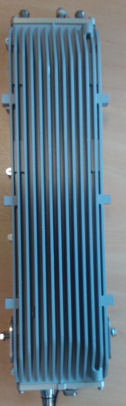
O2J-375AS
Sep 16, 2013Airsynergy Compact Outdoor Pico Base Station
Equipment Class
TNB - Licensed Non-Broadcast Station Transmitter
O2J-235AS
Sep 29, 2011Airsynergy WiMAX Basestation
Equipment Class
TNB - Licensed Non-Broadcast Station Transmitter
O2J-365AS
Sep 13, 2011Airsynergy WiMAX Basestation
Equipment Class
TNB - Licensed Non-Broadcast Station Transmitter
O2J-365T
Dec 19, 2007SCRT
Equipment Class
TNB - Licensed Non-Broadcast Station Transmitter