O2J-375ASAirsynergy Compact Outdoor Pico Base Station
Airspan Communications Limited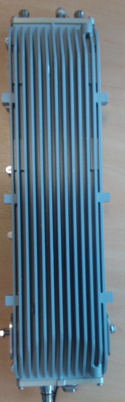
Click to zoom
Application Details
- Equipment Class
- TNB - Licensed Non-Broadcast Station Transmitter
- Date of Grant
- Sep 16, 2013
- Application Purpose
- Original Equipment
- Date of Application
- Aug 15, 2013
- Equipment Note
- Airsynergy Compact Outdoor Pico Base Station
- Frequency Range
- 3655.00000000 - 3695.00000000
- Country
- United Kingdom
Documents & Files
Document Text
Text extracted from the exhibit documents filed with the FCC. Open a document above to read the original.
Users Manual
SYN-UG-018 Revision A0 (draft ver. c) AirSynergy3 Equipment Installation Guide AirSynergy3 Equipment Installation Guide Page 2 | Commercial in Confidence SYN-UG-018 Copyright © Copyright by Airspan Networks Inc., 2013. All rights reserved worldwide. The information contained within this document is proprietary and is subject to all relevant copyright, patent and other laws protecting intellectual property, as well as any specific agreements protecting Airspan Networks Inc. rights in the aforesaid information. Neither this document nor the information contained herein may be published, reproduced or disclosed to third parties, in whole or in part, without the express, prior, written permission of Airspan Networks Inc. In addition, any use of this document or the information contained herein for the purposes other than those for which it is disclosed is strictly forbidden. Airspan Networks Inc. reserves the right, without prior notice or liability, to make changes in equipment design or specifications. Information supplied by Airspan Networks Inc. is believed to be accurate and reliable. However, no responsibility is assumed by Airspan Networks Inc. for the use thereof nor for the rights of third parties which may be effected in any way by the use of thereof. Any representation(s) in this document concerning performance of Airspan Networks Inc. product(s) are for informational purposes only and are not warranties of future performance, either expressed or implied. Airspan Networks Inc. standard limited warranty, stated in its sales contract or order confirmation form, is the only warranty offered by Airspan Networks Inc. in relation thereto. This document may contain flaws, omissions or typesetting errors; no warranty is granted nor liability assumed in relation thereto unless specifically undertaken in Airspan Networks Inc. sales contract or order confirmation. Information contained herein is periodically updated and changes will be incorporated into subsequent editions. If you have encountered an error, please notify Airspan Networks Inc. All specifications are subject to change without prior notice. Product performance figures quoted within this document are indicative and for information purposes only. UK WEE Registration number: WEE/AB0207WZ AirSynergy3 Equipment Installation Guide Page 3 | Commercial in Confidence SYN-UG-018 Table of Contents Copyright ............................................................................................................................................... 2 Table of Contents .................................................................................................................................. 3 Summary of Figures ..................................................................................................................... 5 Summary of Tables ....................................................................................................................... 8 1 About this Guide ........................................................................................................................... 9 1.1 Purpose .................................................................................................................................. 9 1.2 Intended Audience ................................................................................................................ 9 1.3 Conventions........................................................................................................................... 9 1.4 Referenced Documentation ............................................................................................... 10 1.5 Organisation of this Guide ................................................................................................. 10 2 Introduction ................................................................................................................................. 11 2.1 General Overview for use with External Antenna ............................................................ 11 2.1.1 Front Mounted Sector Antenna Arrangement .......................................................... 11 2.1.2 Switched Beam Antenna Arrangement ..................................................................... 12 2.1.3 Dual radio unit arrangement ...................................................................................... 12 2.2 Workflow of Installation ...................................................................................................... 13 2.3 Installation Checklist .......................................................................................................... 13 2.4 Verify Site Requirements .................................................................................................... 14 2.5 Verify Safety Requirements ............................................................................................... 14 2.5.1 Warning of Hazardous Voltages ................................................................................ 14 2.5.2 Adhere to European Directive 1999/519/EC ............................................................. 14 2.6 Verify Installation Requirements ....................................................................................... 15 2.6.1 Verify the Tools ........................................................................................................... 15 2.6.2 Verify the Parts and Kits ............................................................................................. 16 2.6.3 Verify Components ..................................................................................................... 19 3 Installing AirSynergy .................................................................................................................. 22 3.1 Mount the AirSynergy Universal Mounting Plate ............................................................. 22 3.2 Fit Front Sector Antenna to AirSyner…
Text truncated - open the document above for the full version.
Users Manual
Additional User Manual Statements Airsynergy Basestation, FCC ID: O2J-375AS, operating in the 3650-3700 MHz Band. Federal Communications Rules for operation in USA To ensure compliance FCC rules and regulations, the following should be observed: • The 3650-3700 MHz frequency range is a licensed band in the USA and operators must have a valid spectrum license to operate Airsynergy equipment using this band. • The Airsynergy base station requires operation using an Airspan FCC-specific version of Netspan supporting Listen Before Transmit. This management software only permits operation in the 3650-3700 MHz band. • The unit and must be professionally installed. • Any attempt to alter these parameters outside those permitted by the Netspan software or the operator license could be a violation of that license • The correct setting of the following Base Station parameters in Netspan, are critical to the correct operation of equipment in compliance with the rules detailed in 47CFR90 subpart Z (Wireless Broadband Services in the 3650–3700 MHz Band): o Transmit Power o Transmit Frequency o Channel Bandwidth o Carrier Sense Threshold o Carrier Sense Backoff Frames Transmit Power Transmit power is set using the Netspan management software during install /commissioning. For 5MHz channel operation, the maximum permitted EIRP is 5 W. Due to the effective occupied bandwidth and the additive effect of the MIMO antenna, the power setting in Netspan must be set such that: TX power (dBm) + 3dB 1 + Antenna gain (dBi) ≤ 35.5 dBm For 10 MHz channel operation, the maximum permitted EIRP is 10 W. Due to the effective occupied bandwidth and the additive effect of the MIMO antenna, the power setting in Netspan must be set such that: TX power (dBm) + 3dB 1 + Antenna gain (dBi) ≤ 39.0 dBm 1 Add 3dB for additive effect of two antennas Additional User Manual Statements RF Exposure FCC Maximum Permissible Exposure (MPE) limits for equipment operating in the frequency range 1500 – 100,000 MHz is 1.0 mW/cm 2 . Following installation and commissioning, the safe distance from the antenna is the greater of: 20cm Or r cm, where r = √ (PG/4∏S) P: power input to antenna(s) in mW G: numeric gain of antenna relative to isotropic radiator S: power density in mW/cm2 = 1 mW/cm2 The device has two antenna ports, so safe distance from the antenna shall be the greater of: 20 cm or √ (2*PG/4∏S) Which gives 20 cm or √ (0.16*P*G) cm.
Cover Letter(s)
Sulis Consultants Limited Mead House, Longwater Road, Eversley, Hampshire, RG27 0NW, UK Registered in England & Wales, number 05466247 http://www.sulisconsultants.com 29 July 2013 Federal Communications Commission Office of Engineering and Technology Equipment Authorization Division 7345 Oakland Mills Road Columbia, Maryland 21046 Subject: Permanent Confidentiality request for FCC ID: O2J-375AS To whom it may concern Pursuant to sections 0.457 and 0.459 and CFR 47, the applicant requests permanent confidential treatment of the following information accompanying this application: • Schematics • Bills of Materials The above materials contain trade secrets and proprietary information not customarily released to the public. The public disclosure of these matters might be harmful to the applicant and provide unjustified benefits to its competitors Yours Sincerely Charlie Blackham Director
Cover Letter(s)
Mains conducted emissions The A25a and A36 AirSynergy variants use the same: • External mains-dc power supply • Main baseband printed circuit board • Same frequency determining circuitry. The only differences are that final Printed Circuit board Assemblies (PCA) contain different RF filter components to reflect operation at different frequencies. Mains conducted emissions measurements performed on A25a variant are therefore representative of those for A36 variant Please see report SC_TR_87_B_extract
External Photos
FCC ID:O2J-375AS External photos Top Front Face (Rear is flat panel) Bottom
Internal Photos
RF FEM with can fitted Baseband board (top) with cables removed RF FEM without can Baseband board (underside)
Operational Description
FCC ID: O2J-375AS Operational Description Airsynergy A36 is part of Airspan’s broadband fixed cellular wireless access system, operating in the 3650-3700 MHz band. The unit can be deployed as: • A traditional basestation • Or, deployed as a pair of units to extend/improve coverage for existing systems. When deployed as a pair the units are arranged with one configured as Feeder Base and one as Feeder Terminal, using Netspan Management software. Contention Based Protocol is implemented as a base station for the Feeder Base unit and as a terminal device for the Feeder Terminal (see separate document for more details) The Airsynergy WiMAX/802.16 transceiver operates in OFDMA mode with the following characteristics: Configuration Basestation, Feeder Base or Feeder Terminal Frequency range: Frequency of operation is aligned FCC part 90Z and operates within the 3650-3700 MHz band: • 5 MHz channels: Centre frequencies of 3652.5 to 3697.5 MHz • 10 MHz channels Centre frequencies of 3655.0 to 3695.0 MHz Duplex mode: TDD Channel BW: 5 and 10 MHz Max Output Power: 2 x 26 dBm (26 dBm per port, MIMO mode) for 5 MHz channels 2 x 26.5 dBm (26.5 dBm per port, MIMO mode) for 10 MHz channels Modulation rates: BPSK, QPSK, 16QAM, 64QAM, 256QAM The maximum RF output power at each of the antenna ports can be reduced by software. The unit is installed outdoors and typically is mounted on a pole and provides subscribers with "always-on" Internet, high speed data only, or data and voice (VoIP) services and is configured with a unique base station reference number, preventing the Subscriber from relocating to another subscriber premises without authorization.
Parts List/Tune Up Info
AirSynergyTune-up procedure Each Airsynergy is subject to an automated RF Calibration” as part of system test during manufacture. As part of the test, the RF output power level is measured at a number of nominal power level settings. At each level the gain setting is altered as required so that actual transmitted power is the same as the set power level. The gain settings required to do this are unique to each unit and recorded and loaded on the unit as part of the automated system test.
Test Report
Sulis Consultants Limited Mead House, Longwater Road, Eversley, Hampshire, RG27 0NW, UK Registered in England & Wales, number 05466247 http://www.sulisconsultants.com RF Test Report: Airspan AirSynergy 3650-3700 MHz FCC ID:O2J-3675AS SC_TR_91_B Prepared for: Airspan Communications Ltd Capital Point, 33 Bath Road Slough, Berkshire SL1 3UF SC_TR_91_B Page 2 of 24 Contents 1 Revision History .............................................................................................. 4 2 Purpose .......................................................................................................... 4 3 Reference Documents ...................................................................................... 4 4 Test Information ............................................................................................. 5 4.1 Client .................................................................................................... 5 4.2 Test personnel ....................................................................................... 5 4.3 Test sample ........................................................................................... 5 5 Product Description.......................................................................................... 5 6 Test Configuration ........................................................................................... 6 6.1 Test sample and Operating mode ............................................................. 6 6.2 Support equipment ................................................................................. 6 6.3 Test equipment ...................................................................................... 7 6.4 Equipment set-up ................................................................................... 8 7 Summary of Tests performed ............................................................................ 9 8 Transmit Power 47CFR90.1321 ........................................................................ 10 8.1 Requirement and test method ................................................................. 10 8.2 Test results .......................................................................................... 11 9 Spectral Power Density ................................................................................... 12 9.1 Requirement and test method ................................................................. 12 9.2 Test results .......................................................................................... 12 10 Occupied Bandwidth ....................................................................................... 13 11 Conducted Emissions Mask (CEM) ..................................................................... 14 11.1 Requirement and test method ................................................................. 14 11.2 Results ................................................................................................ 14 12 Conducted Spurious Emissions inc. Band Edge ................................................... 17 12.1 Requirement and test method ................................................................. 17 12.2 Results for 5 MHz channels ..................................................................... 18 12.3 Results for 10 MHz channels ................................................................... 20 13 Radiated Spurious Emissions ............................................................................ 22 13.1 Requirement and test method ................................................................. 22 13.2 Results ................................................................................................ 22 SC_TR_91_B Page 3 of 24 Tables Table 1: Equipment under test ................................................................................. 6 Table 2: Support Equipment .................................................................................... 6 Table 3: Test Equipment.......................................................................................... 7 Table 4: Summary of tests performed ....................................................................... 9 Table 5: Transmit power ....................................................................................... 11 Table 6: Transmit power spectral density ................................................................ 12 Table 7: Occupied Bandwidth test results ................................................................ 13 Table 8: Conducted Emissions masks results ............................................................ 14 Table 9: Conducted spurious emissions, 5 MHz channel, RF-3 .................................... 18 Table 10: Conducted spurious emissions, 10 MHz channel, RF-3 ................................. 20 Table 11: Radiated Spurious Emissions ................................................................... 22 Figures Figure 1: Airsynergy configuration for test ................................................................. 8 Figure 2: Transmit Power plots ............................................................................... 11 Figure 3: Transmit Power plots ............................................................................... 12 Figure 4: Occupied Bandwidth plots ........................................................................ 13 Figure 5: 5 MHz channel Spectrum mask plots ......................................................... 15 Figure 6: 10 MHz channel Spectrum mask plots ....................................................... 16 Figure 7: Conducted Spurious Emissions plots, 5 MHz channels .................................. 19 Figure 8: Conducted Spurious Emissions plots, 10 MHz channels ................................ 21 Figure 9: RSE pre-scans, 5 MHz channel .................................................................. 23 Figure 10: RSE Plots – band edge, 5 and 10 MHz channels…
Text truncated - open the document above for the full version.
Test Report
Sulis Consultants Limited Mead House, Longwater Road, Eversley, Hampshire, RG27 0NW, UK Registered in England & Wales, number 05466247 http://www.sulisconsultants.com RF Test Report: Airspan AirSynergy A25a FCC ID:O2J-255AS SC_TR_87_B Prepared for: Airspan Communications Ltd Capital Point, 33 Bath Road Slough, Berkshire SL1 3UF SC_TR_87_B Page 2 of 35 Contents 1 Revision History .............................................................................................. 4 2 Purpose .......................................................................................................... 4 3 Reference Documents ...................................................................................... 4 4 Test Information ............................................................................................. 5 4.1 Client .................................................................................................... 5 4.2 Test personnel ....................................................................................... 5 4.3 Test sample ........................................................................................... 5 5 Product Description.......................................................................................... 6 6 Test Configuration ........................................................................................... 7 6.1 Test sample and Operating mode ............................................................. 7 6.2 Support equipment ................................................................................. 7 6.3 Test equipment (sections 8 to 12) ............................................................ 7 6.4 Test equipment (section 13 and 14) ......................................................... 8 6.5 Equipment set-up ................................................................................... 9 7 Summary of Tests performed ........................................................................... 10 8 Transmit Power 47CFR25.50(h) ........................................................................ 11 8.1 Requirement and test method ................................................................. 11 8.2 Test results .......................................................................................... 12 9 Spectral Power Density 27.50(h)(4) .................................................................. 13 9.1 Requirement and test method ................................................................. 13 9.2 Test results .......................................................................................... 13 10 Conducted Band Edge 27.53(m)(2) .................................................................. 15 10.1 Requirement and test method ................................................................. 15 10.2 Results ................................................................................................ 15 11 Conducted Spurious Emissions ......................................................................... 20 11.1 Requirement and test method ................................................................. 20 11.2 Results ................................................................................................ 20 12 Occupied Bandwidth ....................................................................................... 23 13 Radiated Spurious Emissions ............................................................................ 24 13.1 Requirement and test method ................................................................. 24 13.2 Results ................................................................................................ 24 14 Mains Conducted Emissions ............................................................................. 31 SC_TR_87_B Page 3 of 35 Tables Table 1: Equipment under test ................................................................................. 7 Table 2: Support Equipment .................................................................................... 7 Table 3: Test Equipment for conducted tests .............................................................. 7 Table 4: Summary of tests performed ..................................................................... 10 Table 5: Transmit power ....................................................................................... 12 Table 6: Transmit power spectral density ................................................................ 13 Table 7: Conducted Emissions masks results ............................................................ 15 Table 8: Conducted spurious emissions RF-3 ............................................................ 20 Table 9: Occupied Bandwidth test results ................................................................ 23 Table 10: Radiated Spurious Emissions ................................................................... 24 Figures Figure 1: Airsynergy configuration for test ................................................................. 9 Figure 2: Transmit Power plots ............................................................................... 12 Figure 3: Transmit power spectral density plots ........................................................ 14 Figure 4: Conducted Emissions masks plots: 2305 MHz (5 MHz channels) .................... 16 Figure 5: Conducted Emissions masks plots: 2369 MHz (5 MHz channels) .................... 17 Figure 6: Conducted Emissions masks plots; 2506 MHz (10 MHz channels) .................. 18 Figure 7: Conducted Emissions masks plots; 2566 MHz (10 MHz channels) .................. 19 Figure 8: Conducted Spurious Emissions, 5 MHz channels .......................................... 21 Figure 9: Conducted Spurious Emissions, 10 MHz channels ........................................ 22 Figure 10: Occupied Bandwidths ............................................................................. 23 Figur…
Text truncated - open the document above for the full version.
Test Report
Sulis Consultants Limited Mead House, Longwater Road, Eversley, Hampshire, RG27 0NW, UK Registered in England & Wales, number 05466247 http://www.sulisconsultants.com Frequency Stability Measurements For Airspan Communications Ltd Airsynergy base stations SC_TR_85_B 28 June 2013 SC_TR_85_B Page 2 of 7 Contents 1 Revision History ................................................................................... 3 2 Associated Documents .......................................................................... 3 3 Products Covered ................................................................................. 3 4 Test Configuration ................................................................................ 4 4.1 Measurement method ..................................................................... 5 5 Test Results ......................................................................................... 6 6 Test Location and Equipment ................................................................. 7 Tables Table 1: Products covered by this report ....................................................... 3 Table 2: Equipment under test ..................................................................... 4 Table 3: Test results ................................................................................... 6 Table 4: Test Equipment ............................................................................. 7 Figures Figure 1: Test Configuration ........................................................................ 4 SC_TR_85_B Page 3 of 7 1 Revision History Revision Originator Date Comment A C Blackham 09 Jun 2013 First Issue B C Blackham 28 Jun 2013 Addition of additional frequency variants in table 1. 2 Associated Documents [1] 47CFR2 Title 47 of FCC Rules Part 2 [2] ANSI / TIA-603-C- 2004 TIA Standard: Land Mobile FM or PM – Communications Equipment – Measurement and Performance Standards 3 Products Covered AirSynergy variant Baseband bare PCB Baseband PCA SYN3-CN-00-A425a-000 328-02-143 900-02-242 SYN3-CN-00-U38-000 328-02-143 900-02-242 SYN3-CN-00-A25c-000 328-02-143 900-02-242 SYN3-CN-00-A36-000 328-02-143 900-02-240 SYN3-CN-00-A49-000 328-02-143 900-02-243 Table 1: Products covered by this report These products all show the same printed circuit board and same frequency determining circuitry. The only differences are that final Printed Circuit board Assemblies (PCA) contain different RF filter components to reflect operation at different frequencies. SC_TR_85_B Page 4 of 7 4 Test Configuration Testing was performed on a A49, 4.9GHz unit, that was connected in a real-life representative manner as follows: Equipment under Test In Thermal Chamber Support Equipment Figure 1: Test Configuration Item Part Number Serial Number Airsynergy SYN-3N-00-0A49-000 6BEAD5FFEFA8 Table 2: Equipment under test Airsynergy FSQ PC Co-ax RF cable With attenuation DC supply SC_TR_85_B Page 5 of 7 4.1 Measurement method • The EUT was placed into the thermal chamber and connected to a DC supply and FSQ measuring receiver outside the chamber • The EUT was placed into commissioning mode and set to transmit a test waveform at 4950.0 MHz. • The FSQ is fitted with the WiMAX 802.16e option and was set to reported frequency error in Hz relative to expected frequency of 4950.0 MHz • The Temperature of the chamber was varied between -45°C and +60°C in 10°C steps and the EUT temperature allowed to stabilise for one hour at each. Measurements were recorded using ATE software • Supply voltage was also varied when chamber was at 25°C. • Frequency error was measured by the FSQ and the results shown in section 4. SC_TR_85_B Page 6 of 7 5 Test Results Voltage V) Temp (°C) Freq Error (Hz) Freq Error (ppm) 48.0 -45 -2014.87 -0.40704 48.0 -35 -2266.89 -0.45796 48.0 -25 -1516.82 -0.30643 48.0 -15 892.41 0.180285 48.0 -5 2142.46 0.43282 48.0 5 2268.03 0.458188 48.0 15 2264.09 0.457392 40.8 25 2024.07 0.408903 48.0 25 2218.07 0.448095 55.2 25 2244.91 0.453517 48.0 35 2300.77 0.464802 48.0 45 2352.16 0.475184 48.0 55 2382.26 0.481265 48.0 60 4409.10 0.890727 Table 3: Test results SC_TR_85_B Page 7 of 7 6 Test Location and Equipment Testing was performed at: Airspan Communication Ltd: Capital Point, 33 Bath Road Slough, SL1 3UF UK By Parimal Modeshia of Airspan Communications Ltd and Charlie Blackham of Sulis Consultants Ltd Item Serial Number Calibration Due R&S FSQ 26 100409 2014-07-03 Table 4: Test Equipment
Test Setup Photos
O2J-375AS_test_set-up_photos EUT configuration Substitution measurement
Contact Information
Applicant
Mike Livingstone(VP Engineering)
Technical Contact
Sulis Consultants LtdCharlie F J Blackham
[email protected]07946 624317
Mead House · Eversley · United Kingdom
Test Firm
Eurofins Hursley LtdAndrew Coombes
Technical Specifications
| # | Rule Parts | Frequency Range | Power Output | Emission | Tolerance |
|---|---|---|---|---|---|
| 2 | 9 | 3.65 GHz - 3.69 GHz | 7.852 W | 10M0W7D | 8 ppm |
Other Applications from Airspan Communications Limited
O2J-CBATG
Sep 03, 20264G/5G Small Cell Transportable Base Station used for testing ATG network installations.
Equipment Class
TNB - Licensed Non-Broadcast Station Transmitter
O2J-235AS
Sep 29, 2011Airsynergy WiMAX Basestation
Equipment Class
TNB - Licensed Non-Broadcast Station Transmitter
O2J-365AS
Sep 13, 2011Airsynergy WiMAX Basestation
Equipment Class
TNB - Licensed Non-Broadcast Station Transmitter
O2J-070T
May 05, 2010700 MHz SCRT
Equipment Class
TNB - Licensed Non-Broadcast Station Transmitter
O2J-365T
Dec 19, 2007SCRT
Equipment Class
TNB - Licensed Non-Broadcast Station Transmitter