O2J-235ASAirsynergy WiMAX Basestation
Airspan Communications Limited
Click to zoom
Application Details
- Equipment Class
- TNB - Licensed Non-Broadcast Station Transmitter
- Date of Grant
- Sep 29, 2011
- Application Purpose
- Original Equipment
- Date of Application
- Sep 27, 2011
- Equipment Note
- Airsynergy WiMAX Basestation
- Frequency Range
- 2347.90000000 - 2347.90000000
- Country
- United Kingdom
Documents & Files
Document Text
Text extracted from the exhibit documents filed with the FCC. Open a document above to read the original.
Users Manual
SYN-UG-007 Rev 1 AirSynergy Equipment Installation Guide AirSynergy Equipment Installation Guide Page 2 Commercial in Confidence SYN-UG-007 Rev 1 Copyright © Copyright by Airspan Networks Inc., 2011. All rights reserved worldwide. The information contained within this document is proprietary and is subject to all relevant copyright, patent and other laws protecting intellectual property, as well as any specific agreements protecting Airspan Networks Inc. rights in the aforesaid information. Neither this document nor the information contained herein may be published, reproduced or disclosed to third parties, in whole or in part, without the express, prior, written permission of Airspan Networks Inc. In addition, any use of this document or the information contained herein for the purposes other than those for which it is disclosed is strictly forbidden. Airspan Networks Inc. reserves the right, without prior notice or liability, to make changes in equipment design or specifications. Information supplied by Airspan Networks Inc. is believed to be accurate and reliable. However, no responsibility is assumed by Airspan Networks Inc. for the use thereof nor for the rights of third parties which may be effected in any way by the use of thereof. Any representation(s) in this document concerning performance of Airspan Networks Inc. product(s) are for informational purposes only and are not warranties of future performance, either expressed or implied. Airspan Networks Inc. standard limited warranty, stated in its sales contract or order confirmation form, is the only warranty offered by Airspan Networks Inc. in relation thereto. This document may contain flaws, omissions or typesetting errors; no warranty is granted nor liability assumed in relation thereto unless specifically undertaken in Airspan Networks Inc. sales contract or order confirmation. Information contained herein is periodically updated and changes will be incorporated into subsequent editions. If you have encountered an error, please notify Airspan Networks Inc. All specifications are subject to change without prior notice. Product performance figures quoted within this document are indicative and for information purposes only. UK WEE Registration number: WEE/AB0207WZ AirSynergy Equipment Installation Guide Page 3 Commercial in Confidence SYN-UG-007 Rev 1 Table of Contents Copyright ................................................................................................................................................. 2 Table of Contents .................................................................................................................................... 3 Summary of Figures ................................................................................................................................ 5 Summary of Tables ................................................................................................................................. 6 1 About This Guide ............................................................................................................................ 7 1.1 Purpose ................................................................................................................................... 7 1.2 Intended Audience .................................................................................................................. 7 1.3 Conventions ............................................................................................................................ 7 1.4 Organisation of this Guide ....................................................................................................... 8 2 Introduction ...................................................................................................................................... 9 2.1 General Overview ................................................................................................................... 9 2.1.1 Sector Antenna arrangement .......................................................................................... 9 3 Get Started .................................................................................................................................... 10 3.1 Workflow of Installation ......................................................................................................... 10 3.2 Installation Checklist ............................................................................................................. 11 4 Verify Prerequisites ....................................................................................................................... 12 4.1 Verify Site Requirements ...................................................................................................... 12 4.2 Verify Safety Requirements .................................................................................................. 12 4.2.1 Warn of Hazardous Voltages ........................................................................................ 12 4.2.2 Adhere to European Directive 1999/519/EC ................................................................. 12 4.3 Verify Installation Requirements ........................................................................................... 13 4.3.1 Verify the Tools ............................................................................................................. 13 4.3.2 Verify the Parts and Kits ................................................................................................ 13 4.3.3 .............................................................................................................................................. 14 4.3.4 Verify Components ........................................................................................................ 15 5 Install the AirSynergy mounting plate .................................................................................…
Text truncated - open the document above for the full version.
Cover Letter(s)
Sulis Consultants Limited Mead House, Longwater Road, Eversley, Hampshire, RG27 0NW, UK Registered in England & Wales, number 05466247 http://www.sulisconsultants.com 17 th August 2011 Federal Communications Commission Office of Engineering and Technology Equipment Authorization Division 7345 Oakland Mills Road Columbia, Maryland 21046 Subject: Permanent Confidentiality request for FCCID: O2J-235AS To whom it may concern Pursuant to sections 0.457 and 0.459 and CFR 47, the applicant requests permanent confidential treatment of the following information accompanying this application: Schematics: 900-02-005-b2_2.3GHz-variant-baseband.pdf schematics 328-01-007_2.3_GHz_FEM.pdf Parts List: 900_02_005_B2_PCA_Baseband_2.3_2.7GHz-BoM.pdf 900_06_094_C0_PCA_FEM_2.3_2.4GHz_BoM.pdf The above materials contain trade secrets and proprietary information not customarily released to the public. The public disclosure of these matters might be harmful to the applicant and provide unjustified benefits to its competitors Yours Sincerely Charlie Blackham Director
External Photos
FCC ID:O2J-235AS External photos Top Front Face (Rear is flat panel) Bottom
ID Label/Location Info
FCC ID:O2J-235AS Label FCC ID:O2J-235AS
Internal Photos
Internal Photo Baseband board (top) Baseband board (underside) RF FEM without cans
Operational Description
TCB Question: The brochure says Software Defined Radio. Is this just a marketing term or is it SDR as defined by the FCC in Part 2.944? Applicant Answer: No, it is not a Software Defined Radio. TCB Question: The brochure lists many bands and many technology types. Please confirm that this device does not support any bands other than the 2.3 GHz band and only WiMAX technology. Applicant Answer: It does not support LTE or any technology other than WiMAX. It only operates in the 2.3 GHz band. TCB Question: The Operation Description states an output power of 30 dBm. The test report shows a measurement of 28.8 dBm composite. Please confirm that device was transmitting at maximum output power. Applicant Answer: It was set to maximum (30 dBm) during the testing. It is 30 dBm composite. TCB Question: Please confirm that the device does not support other ‘types’ of modulation. Applicant Answer: It does not support other types of modulation. Only OFDMA.
Operational Description
Additional Airsynergy User Manual Statements Airsynergy basestation,FCC ID: O2J-235AS, operating in the 2305-2320 and 2345-2360 MHz WCS Bands. Federal Communications Rules for operation in USA The correct setting of the following Base Station parameters in Netspan, are critical to the correct operation of equipment in compliance with the rules detailed in 47CFR27subpart C: Transmit Power Transmit Frequency Channel Bandwidth Any attempt to alter these parameters outside those permitted by the Netspan software or the operator license could be a violation of that license Transmit Power/ Tune-up Transmit power is set using the Netspan management software during install /commissioning. The unit may transmit with a power of up to 30dBm at each antennaport when connected to cross polarised antenna with maximum gain of 18dBi RF Exposure FCC Maximum Permissible Exposure (MPE) limits for equipment operating in the frequency range 1500 – 100,000 MHz is 1.0 mW/cm 2 . Following installationand commissioning, the safe distance from the antenna is the greater of: 20cm Or r cm, where r = √ (PG/4∏S) P: power input to antenna(s)in mW G: numeric gain of antenna relative to isotropic radiator S: power density in mW/cm2 = 1 mW/cm2 The device has two antenna ports, so safe distance from the antenna shall be the greater of: 20 cm or √ (2*PG/4∏S) Which gives a safe distance of 71cm when used with a 18dBi antenna.
Operational Description
FCC ID:O2J-235AS Operational Description V2 A Base station radio, Airsynergy, is part of a WiMAX broadband fixed cellular wireless access system. The system provides a radio link between an end-user (a subscriber) and a network to give high-speed data access. The Airsynergy transceiver/receiver (Up to 64 QAM modulation) uses OFDMA and operating in TDD duplexing mode, equipped with an external antenna. The maximum RF output powerat each of the antenna portsis 30dBm and it can be reduced by software. The Airsynergy transmitter has two TX channels for MIMO operation mode. The unit is installed outdoors and typically is mounted on a pole and provides subscribers with "always-on" Internet, high speed data only, or data and voice (VoIP) services and is configured with a unique base station reference number, preventing the Subscriber from relocating to another subscriber premises without authorization.
Operational Description
Air-Synergy 4G Pico Base Station with Integrated Wireless Backhaul The world’s most compact and versatile 4G Pico Base Station Wireless Broadband Operators are currently experiencing an unprecedented growth in data traffic, which today’s networks are struggling to satisfy. As part of a heterogeneous network, Pico Base Stations address this problem by being located closer to the end user, providing much higher aggregate data rates. The issue with today’s Pico Base Stations has been the difficulty in connecting them with the rest of the network. Air-Synergy solves this problem by combining a 4G Pico Base Station with an integrated, high capacity, self-connecting wireless backhaul. Air-Synergy is Airspan’s latest generation of Software Defined Radio (SDR) Base Stations, which supports multiple radio interfaces to allow both access and wireless backhaul to be provided from the same unit. Air-Synergy is an all-in-one compact Pico Base Station, which supports a wide range of radio interfaces using Airspan’s field proven SDR technology, including WiMAX and LTE 4G technologies. The integration of both backhaul and access technologies is an industry first, and redefines the way in which networks can be constructed. This technique enables Air-Synergy to be deployed on street furniture (e.g. lamp posts), with connections automatically established through neighbouring nodes to establish a backhaul connection with the network. A key feature of the Air-Synergy technology is the ability to self-configure, self- connect, self-heal and self-optimise when deployed as a network of elements. At the same time Air-Synergy provides guaranteed levels of service with Quality of Service (QoS) characteristics in line with the requirements of the access interface 4G ACCESS Air-Synergy supports either LTE or 802.16e WiMAX access technologies in addition to Airspan’s Intelligent Wireless Backhaul technology, iBridge. WiMAX provides anytime, anywhere mobile access to broadband services at much higher capacity than is possible with 3G networks. Airspan’s LTE solution is compliant with the 3GPP standards and interoperable with commercial UE devices. Air-Synergy is based on Airspan’s Software Defined Radio (SDR) technology, and as a result supports a range of air interfaces through remote software updates. INTEGRATED WIRELESS BACKHAUL Air-Synergy uniquely provides an integrated wireless backhaul solution using Airspan’s iBridge technology. iBridge is a self-configuring, self-connecting point- to-multipoint backhaul solution, which automatically extends the reach of the network from existing Points of Interconnect (POI). iBridge supports multi-hop relay connections, providing either LTE or WiMAX coverage from each node in addition to the iBridge backhaul functionality. SUSTAINABLE Air-Synergy Pico Cells can be installed on existing street poles (lamp posts or utility poles) which are either OPEX free, or have a nominal on-going OPEX, thus avoiding the recurring costs associated with a traditional Macro Base Station. Air-Synergy also requires a fraction of the power of a Macro Base Station, which further reduces the OPEX, and also allows renewable energy sources, such as solar panels, to be used. ALL-IN-ONE SOLUTION Air-Synergy consists of a single self- contained unit, removing the need for an equipment rack or any indoor equipment. Units are powered from a compact power supply unit based on commercial Power Over Ethernet technology. PLUG AND PLAY Air-Synergy supports automated configuration from the management system, simplifying the installation of each base station. This automation, coupled with the self-connecting iBridge backhaul results in a true plug and play solution, allowing service to be rapidly deployed. REDUCED CAPEX / OPEX Air-Synergy is a compact all-outdoor 4G Pico Base Station, which can be installed without conventional indoor infrastructure and associated power and air- conditioning systems. The integration of wireless backhaul reduces the equipment installed per site, as separate backhaul infrastructure is not required. This in turn reduces spares holding and inventories. The iBridge backhaul supports self healing, allowing the network to automatically recover in the event of failure. This increases overall service availability and customer satisfaction. FLEXIBLE ARCHITECTURE The iBridge network can support different topologies as new elements are added to the network, enabling a highly flexible and versatile deployment. Each Air- Synergy node can adopt both access and backhaul functionality, automatically changing backhaul role from termination to relay to ensure a dynamic self- adapting architecture. Through the use of Airspan’s real-time iBridge SON Server, iBridge supports self- continuous optimisation of backhaul links, ensuring interference between iBridge nodes is minimised and delivering end-to-end QOS across the network with minimal spectrum consumption. RADIO PLANNING Air-Synergy is designed to integrate with standardised WiMAX and LTE SON solutions. When coupled with the iBridge SON Server, this allows a broadband wireless network to be deployed without the need for extensive, formal planning. Nodes are incrementally added in the target service area until the desired coverage is achieved. The products self-configure, self-connect, and self- optimise. In addition, unlike conventional mobile network planning and design, expansion of the coverage area can be optimised and adapted depending on the local need. The “Pico Cell” technology solution is designed for deployment onto standard utility poles, for example telephone poles, street lamps or power poles. Coverage is created by deploying multiple cells in chains or clusters, depending on the desired wireless service footprint. RADIO INTERFACE Version: Release 8/9 (10 in future) Operational Frequency Bands: 2.3GHz 2.6GHz 3.5GHz 800MHz 700MHz Duplex: FDD & TDD Max Channel BW: 10MHz (20MHz in future) Max Transmit Power: 2 x +27dBm & 2x +30dBm opti…
Text truncated - open the document above for the full version.
Parts List/Tune Up Info
FCC ID: O2J-235AS Tune-up procedure Each Airsynergy is subject to an automated RF Calibration” as part of system test during manufacture. As part of the test, the RF output power level is measured at a number of nominal power level settings. At each level thegain setting is altered as required so that actual transmitted power is the same as the set power level. The gain settings required to do this are unique to each unit and recorded and loaded on the unit as part of the automated system test.
Parts List/Tune Up Info
Additional Airsynergy User Manual Statements Airsynergy basestation,FCC ID: O2J-235AS, operating in the 2305-2320 and 2345-2360 MHz WCS Bands. Federal Communications Rules for operation in USA The correct setting of the following Base Station parameters in Netspan, are critical to the correct operation of equipment in compliance with the rules detailed in 47CFR27subpart C: Transmit Power Transmit Frequency Channel Bandwidth Any attempt to alter these parameters outside those permitted by the Netspan software or the operator license could be a violation of that license Transmit Power/ Tune-up Transmit power is set using the Netspan management software during install /commissioning. The unit may transmit with a power of up to 30dBm at each antennaport when connected to cross polarised antenna with maximum gain of 18dBi RF Exposure FCC Maximum Permissible Exposure (MPE) limits for equipment operating in the frequency range 1500 – 100,000 MHz is 1.0 mW/cm 2 . Following installationand commissioning, the safe distance from the antenna is the greater of: 20cm Or r cm, where r = √ (PG/4∏S) P: power input to antenna(s)in mW G: numeric gain of antenna relative to isotropic radiator S: power density in mW/cm2 = 1 mW/cm2 The device has two antenna ports, so safe distance from the antenna shall be the greater of: 20 cm or √ (2*PG/4∏S) Which gives a safe distance of 71cm when used with a 18dBi antenna.
RF Exposure Info
Additional Airsynergy User Manual Statements Airsynergy basestation,FCC ID: O2J-235AS, operating in the 2305-2320 and 2345-2360 MHz WCS Bands. Federal Communications Rules for operation in USA The correct setting of the following Base Station parameters in Netspan, are critical to the correct operation of equipment in compliance with the rules detailed in 47CFR27subpart C: Transmit Power Transmit Frequency Channel Bandwidth Any attempt to alter these parameters outside those permitted by the Netspan software or the operator license could be a violation of that license Transmit Power/ Tune-up Transmit power is set using the Netspan management software during install /commissioning. The unit may transmit with a power of up to 30dBm at each antennaport when connected to cross polarised antenna with maximum gain of 18dBi RF Exposure FCC Maximum Permissible Exposure (MPE) limits for equipment operating in the frequency range 1500 – 100,000 MHz is 1.0 mW/cm 2 . Following installationand commissioning, the safe distance from the antenna is the greater of: 20cm Or r cm, where r = √ (PG/4∏S) P: power input to antenna(s)in mW G: numeric gain of antenna relative to isotropic radiator S: power density in mW/cm2 = 1 mW/cm2 The device has two antenna ports, so safe distance from the antenna shall be the greater of: 20 cm or √ (2*PG/4∏S) Which gives a safe distance of 71cm when used with a 18dBi antenna.
Test Report
TEST REPORT FROM RFI GLOBAL SERVICES LTD Test of: Airsynergy SYN2-CN-00-U40-000 FCC ID: O2J-235AS To: FCC Parts 2.1046; 2.1049; 2.1051; 2.1053; 27.50 & 27.53 Test Report Serial No: RFI-RPT-RP82269JD02A V2.0 Version 2.0 supersedes all previous versions This Test Report Is Issued Under The Authority Of Chris Guy, Head of Global Approvals: pp Checked By: Nick Hooper Signature: Date of Issue: 30 August 2011 This report is issued in Adobe Acrobat portable document format (PDF). It is only a valid copy of the report if it is being viewed in PDF format with the following security options not allowed: Changing the document, Selecting text and graphics, Adding or changing notes and form fields. This report may not be reproduced other than in full, except with the prior written approval of RFI Global Services Ltd. The results in this report apply only to the sample(s) tested. TEST REPORT SERIAL NO: RFI-RPT-RP82269JD02A V2.0 VERSION NO. 2.0 ISSUE DATE: 30 AUGUST 2011 Page 2 of 47 RFI Global Services Ltd This page has been left intentionally blank. TEST REPORT SERIAL NO: RFI-RPT-RP82269JD02A V2.0 VERSION NO. 2.0 ISSUE DATE: 30 AUGUST 2011 RFI Global Services Ltd Page 3 of 47 Table of Contents 1. Customer Information .................................................................................................................. 4 2. Summary of Testing ..................................................................................................................... 5 2.1. General Information 5 2.2. Summary of Test Results 5 2.3. Methods and Procedures 5 2.4. Deviations from the Test Specification 5 3. Equipment Under Test (EUT) ....................................................................................................... 6 3.1. Identification of Equipment Under Test (EUT) 6 3.2. Description of EUT 6 3.3. Modifications Incorporated in the EUT 6 3.4. Additional Information Related to Testing 7 3.5. Support Equipment 8 4. Operation and Monitoring of the EUT during Testing ............................................................... 9 4.1. Operating Modes 9 4.2. Configuration and Peripherals 9 5. Measurements, Examinations and Derived Results ................................................................ 10 5.1. General Comments 10 5.2. Test Results 11 5.2.1. Transmitter Carrier Output Power (EIRP) 11 5.2.2. Transmitter Average Power Spectral Density 14 5.2.3. Transmitter Peak to Average Power Ratio 17 5.2.4. Transmitter Occupied Bandwidth 18 5.2.5. Transmitter Conducted Emissions 21 5.2.6. Transmitter Conducted Emissions at Band Edges 28 5.2.7. Transmitter Radiated Spurious Emissions at Band Edges 44 6. Measurement Uncertainty .......................................................................................................... 46 Appendix 1. Test Equipment Used ................................................................................................ 47 TEST REPORT SERIAL NO: RFI-RPT-RP82269JD02A V2.0 VERSION NO. 2.0 ISSUE DATE: 30 AUGUST 2011 Page 4 of 47 RFI Global Services Ltd 1. Customer Information Company Name: Airspan Communications Ltd. Address: Capital Point 33 Bath Road Slough Berkshire SL1 3UF United Kingdom TEST REPORT SERIAL NO: RFI-RPT-RP82269JD02A V2.0 VERSION NO. 2.0 ISSUE DATE: 30 AUGUST 2011 RFI Global Services Ltd Page 5 of 47 2. Summary of Testing 2.1. General Information Specification Reference: 47CFR27 Specification Title: Code of Federal Regulations Volume 47 (Telecommunications) 2010: Part 27 Subpart C (Miscellaneous Wireless Communication Services) Specification Reference: Customer Test Plan Specification Title: SC_AIR_TP04_A_august-2011 Site Registration: 209735 Location of Testing: RFI Global Services Ltd, Wade Road, Basingstoke, Hampshire, RG24 8AH. Test Dates: 08 August 2011 to 09 August 2011 2.2. Summary of Test Results FCC Reference (47CFR) Measurement Result Part 27.50(a)(ii) / 2.1046 Power Limits and Duty Cycle Part 27.50(a)(1) / 2.1046 Average Power Spectral Density Part 27.50(a)(1)(B) Peak to Average Power Ratio Part 2.1049 Transmitter Occupied Bandwidth Part 27.53(a)(1) / 2.1051 Transmitter Conducted Emissions Part 27.53(a)(1) / 2.1051 Transmitter Conducted Emissions at Band Edges Part 27.53(a)(1) / 2.1053 Transmitter Radiated Spurious Emissions Part 27.53(a)(1) / 2.1053 Transmitter Radiated Emissions at Band Edges Key to Results = Complied = Did not comply 2.3. Methods and Procedures Reference: ANSI/TIA-603-C-2004 Title: Land Mobile Communications Equipment, Measurements and performance Standards 2.4. Deviations from the Test Specification For the measurements contained within this test report, there were no deviations from, additions to, or exclusions from the test specification identified above. TEST REPORT SERIAL NO: RFI-RPT-RP82269JD02A V2.0 VERSION NO. 2.0 ISSUE DATE: 30 AUGUST 2011 Page 6 of 47 RFI Global Services Ltd 3. Equipment Under Test (EUT) 3.1. Identification of Equipment Under Test (EUT) Brand Name: Airspan Model Name or Number: Airsynergy SYN2-CN-00-U40-000, P/N 902-03-205 Serial Number: 9B2312FFFF23 - baseband board Hardware Version Number: Synergy2 revA FCC ID Number: O2J-235AS Description: RF Filter for Port 1 Brand Name: WeverCom Model Name or Number: WVC-2311D2354-12M02B Serial Number: S11050005 Description: RF Filter for Port 2 Brand Name: WeverCom Model Name or Number: WVC-2311D2354-12M02B Serial Number: S11050007 Description: RF Cable #1 - 1.25 metres Brand Name: Andrew Model Name or Number: Sureflex L4NRA-PNMNF-1M25 Serial Number: 05ACZ10906995 Description: RF Cable #2 - 1.25 metres Brand Name: Andrew Model Name or Number: Sureflex L4NRA-PNMNF-1M25 Serial Number: 05ACZ10906961 3.2. Description of EUT The equipment under test was a Airsynergy P2P WiMax Base Station operating in the 2.3 GHz frequency band. The Base Station was connected to two RF Filters via two RF cables, both 1.25 metres in length. 3.3. Modifications Incorporated in the EUT No modifications were applied to the EUT during testing. TEST REPORT SERIA…
Text truncated - open the document above for the full version.
Test Report
Sulis Consultants Limited Mead House, Longwater Road, Eversley, Hampshire, RG27 0NW, UK Registered in England & Wales, number 05466247 http://www.sulisconsultants.com 6 th September2011 Federal Communications Commission Office of Engineering and Technology Equipment Authorization Division 7345 Oakland Mills Road Columbia, Maryland 21046 Subject: Report RFI-RPT-RP82269JD02A V2error To whom it may concern There is a minor error in section 3.4 of the above report which arises from confusion around information provided by the customer to the test house. I confirm that the device only supports operation in 3.5 MHz channel bandwidths, as tested in the report, and does not support operation in 5.0 nor 10.0 MHz bandwidths. Yours Sincerely Charlie Blackham Director
Test Report
Sulis Consultants Limited Mead House, Longwater Road, Eversley, Hampshire, RG27 0NW, UK Registered in England & Wales, number 05466247 http://www.sulisconsultants.com Frequency Stability Measurements For Airspan Communications Ltd Airsynergy 2.3 GHzTDD basestation FCC ID:O2J-235AS SC_TR_39_B 05 September2011 SC_TR_39_BPage 2 of 6 Contents 1Revision History................................................................................3 2Associated Documents........................................................................3 3Test Configuration.............................................................................4 3.1Measurement method................................................................... 5 4Test Results......................................................................................5 5Test Equipment.................................................................................6 Tables Table 1: Equipment under test................................................................... 4 Table 2: Test results................................................................................5 Table 3: List of Test Equipment.................................................................. 6 Figures Figure 1: Test Configuration......................................................................4 Figure 2: Example FSQ data capture (48V at 20°C).......................................6 SC_TR_39_BPage 3 of 6 1Revision History RevisionOriginatorDateComment AC Blackham16August2011First Issue BC Blackham05 September2011Typo corrected in table 2 2Associated Documents [1]47CFR2Title 47 of FCC Rules Part 2 [2] ANSI / TIA-603-C- 2004 TIA Standard: Land Mobile FM or PM – Communications Equipment – Measurement and Performance Standards SC_TR_39_BPage 4 of 6 3Test Configuration The unitshall be connected in a real-life representative manner as follows: Equipment under Test In Thermal Chamber Support Equipment Figure 1: Test Configuration ItemPart NumberSerial Number AirsynergySYN2-CN-00-U40-0009B2312FFFF23 (baseband board) Table 1: Equipment under test Airsynergy FSQ POE injector Co-ax RF cable With attenuation Drop cable (Cat5) 48 V supply SC_TR_39_BPage 5 of 6 3.1Measurement method The EUT was placed into the thermal chamber and connected to a DC supply and FSQ measuring receiver outside the chamber The EUT was placed into commissioning mode and set to transmit a test waveform at 2347.9 MHz. The FSQ is fitted with the WiMAX 802.16e option and was set to reported Frequency error in Hz relative to expected frequency of 2347.9 MHz The Temperature of the chamber was variedbetween -30°C and +50°C in 10°C steps and the EUT temperature allowed to stabilise for one hour at each. Supply voltage was also varied when chamber was at 20°C. Frequency error was measured by the FSQ and the results shown in section 4. 4TestResults Temp (°C) Voltage (V dc) Freq Err (Hz) Freq Error (ppm) Tx1Tx2Tx1Tx2 -3048-3176-3194-1.4-1.4 -2048-2936-2925-1.3-1.2 -1048-2995-2988-1.3-1.3 048-3049-3046-1.3-1.3 1048-2418-2408-1.0-1.0 20 40.8-900-902-0.4-0.4 48-904903-0.40.4 55.2-891-896-0.4-0.4 3048-2038-2045-0.9-0.9 4048-2617-2593-1.1-1.1 5048-3239-3237-1.4-1.4 Table 2: Testresults SC_TR_39_BPage 6 of 6 Figure 2: ExampleFSQ data capture (48V at 20°C) 5Test Equipment ItemSerial NumberCalibration R&S FSQ 26Airspan No 005316 S/N 2…
Text truncated - open the document above for the full version.
Contact Information
Applicant
Mike Livingstone(VP Engineering)
Technical Contact
Test Firm
UL VS LtdDarren Rust
Technical Specifications
| # | Rule Parts | Frequency Range | Power Output | Emission | Tolerance |
|---|---|---|---|---|---|
| 2 | 27 | 2.35 GHz - 2.35 GHz | 45.7 W | 3M50D1D | 8 ppm |
Other Applications from Airspan Communications Limited
O2J-CBATG
Sep 03, 20264G/5G Small Cell Transportable Base Station used for testing ATG network installations.
Equipment Class
TNB - Licensed Non-Broadcast Station Transmitter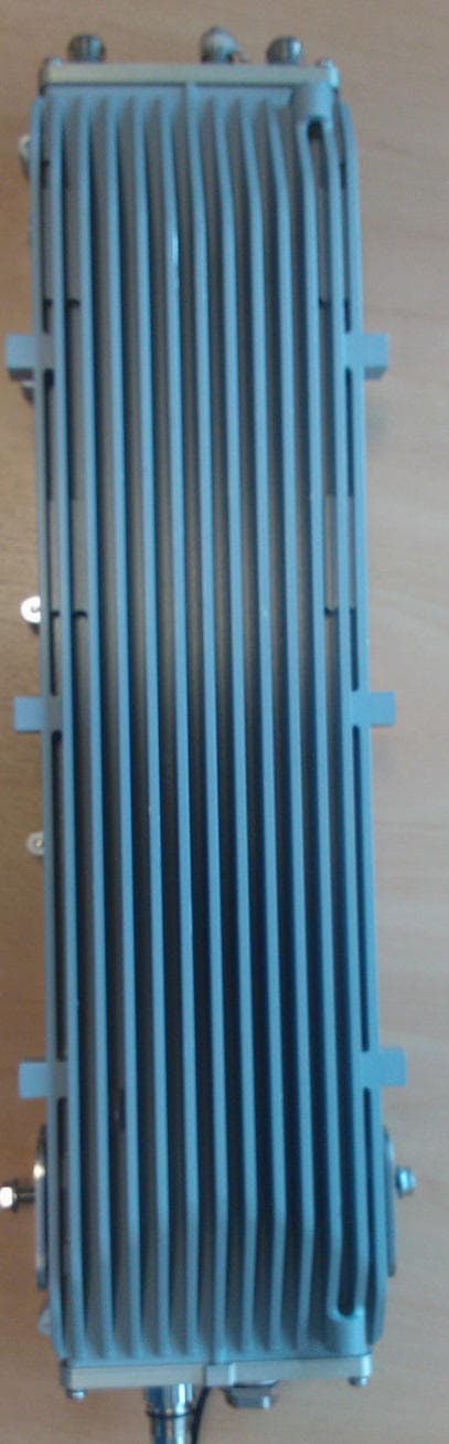
O2J-375AS
Sep 16, 2013Airsynergy Compact Outdoor Pico Base Station
Equipment Class
TNB - Licensed Non-Broadcast Station Transmitter
O2J-365AS
Sep 13, 2011Airsynergy WiMAX Basestation
Equipment Class
TNB - Licensed Non-Broadcast Station Transmitter
O2J-070T
May 05, 2010700 MHz SCRT
Equipment Class
TNB - Licensed Non-Broadcast Station Transmitter
O2J-365T
Dec 19, 2007SCRT
Equipment Class
TNB - Licensed Non-Broadcast Station Transmitter