O2MISP5900FPager Receiver
ISE Telecommunication Co Ltd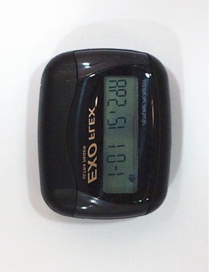
Click to zoom
Application Details
- Equipment Class
- CXX - Communications Rcvr for use w/ licensed Tx and CBs
- Date of Grant
- Oct 11, 2000
- Application Purpose
- Original Equipment
- Date of Application
- Sep 26, 2000
- Equipment Note
- Pager Receiver
- Frequency Range
- 929.01250000 - 931.98750000
- Company
- ISE Telecommunication Co Ltd
- Country
- South Korea
Documents & Files
Document Text
Text extracted from the exhibit documents filed with the FCC. Open a document above to read the original.
Users Manual
USER'S MANUAL ISP-5900 FLEX TABLE OF CONTENT 1. Control Button Illustration 2. List of Features and Specifications 3. LCD Referrence Guide 4. Power On 5. Power Off 6. Service Area Indicator 7. Message Indicator 8. Reading Messages 9. Deleting Messages 10. Message Lock and Release Function 11. Selecting the Incoming Message Alert 12. Setting the Date and Time 13. Setting the Alarm 14. Low Battery Indicator 15. Care and Maintance 16. Patent Information 17. Warranty Information 18. One Year Full Warranty Turms and Conditons 1. Control Buttons Illustration . MENU BUTTON ( Function Key ) . SELECT BUTTON . LCD ( Flex Pager Display Window 2. Features and Specification 1) Paging Bit Per Second : 1600bps, 3200bps, 6400bps 2) Store Up to 16 Messages 3) Lock Up to 12 Messages 4) AGC Function 5) Unread Message Indicator 6) Message Delete Function 7) Duplicate Message Indicator 8) Date and Time Display Function 9) Alarm Function 10) Beep and Melody Function 11) Vibrate Function 12) Low Battery Indicator 13) Service Area Indicator 14) Backlight Function 15) Lamp 16) Care and Mantainance Instruction 17) Regulatory Agency Compliance 18) One Year Full Warranty Terms and Conditions 3. LCD Referrence Guide : Alert Indicator : Alarm Indicator : Lock Indicator : Low Battery Indicator : Duplicate Message Indicator : Service Area Indicator : More than 13 Messages Indicator 4. Turning Your Pager On While your pager is in the Off Mode, press and hold any button for at least three (3) seconds then release. You will hear an alert tone, then the pager will vibrate. Now your pager is ON. LCD Display Initial Display When Turned ON Stand By Mode 5. Turning Your Pager Off While in the Stand By Mode, press the Menu button three (3) times until LCD displays, "POWER OFF ?" Press the Select button to say "yes." Stand By Mode Press the Menu button 3 times Press the Select Button Off Mode 6 Finding the Service Area While in the Stand By Mode, if the Service Indicator is displayed, then you are in the service area. You will be able to receive messages. Service Area However, if LCD display does not show the Service Indicator, the pager is unable to receive any messages. Service Area is out of reach 7. Message Indicator When a new message is received, your pager will either alert or vibrate for 8 seconds ( and the backlight will go on. ) On the LCD, the Message Indicator will appear. You can push any button to stop the pager from continuing to alert or vibrate. Message Indicator Sample Message When a new message is received, a number will show up to indicate how many messages you have. This number contains all unread messages and periodically message alert will sound. Three Unread Messages When a Duplicate Message is detected, the Duplicate Message Indicator will appear. Duplicate Message Indicator 8. Reading Messages From Stand By Mode, if the message is new, the following symbol is displayed, [ ]. The number inside the brackets indicate how many new massages you have received. If no button is presses for the first 16 seconds, the pager will automatically store the message. New Message ("[01]" indicates quantity of new messages) Press the Select Button Stored Message (Displays the time and date when the message was first received) Press the Select Button to Read If no message was left, "NO Page" will be displayed If the message is longer than 13 characters, the More than 13 Characters Indicator will show. The Right Arrow indicates additional characters Press the Select Button The Rest of your message is displayed 9. Deleting Messages You ca n delete all yo ur messages a t o nce. Stand By Mode press the Menu button 4 times press the Select button Stand By Mode After all messages have been deleted, the pager will go back to Stand By Mode. However, locked messages are still stored. 10. Locking and Unlocking Your Messages Up to 10 Stored Messages can be locked. Until a Locked Message is Unlocked, it remains in locked position. See important note at the bottom of this section for the exception to the rule. To lock a message, yo u need to display the message yo u w ant to lock. Whe n the ba tter y has been completely discharged and you replace the battery locked messages will also obliterated. If you want to lock the message press menu button. The locked message will turn to unlock and if it was in unlocked message, it will turn to lock mode. If yo u press select butoo n yo u ca n obtai n a mode yo u desire. If you press menu button, the display shows erase and if you press select button, the message goes off. Select the message you want to Lock While holding down the Select button, press Menu button Locked Message To Unlock a message, press and hold Select button, then press the Menu button. If all 10 messages have been locked and you try to lock another message, the following message will be displayed on your pager. You must unlock at least one message before you can lock an additional message. Important Note: You can still lose locked message if the battery drops too low. Your pager will display, "BATT LOW". Try to replace the battery as soon as possible. This will prevent you from losing an important message. See section 14 for more information. 11. Selecting Inco mi ng Message Alert Tone or Vibratio n In the Initial Setting, the Alert Tone is set. However, you may change from Alert to Vibration Mode. Initial Setting (Alert Mode) press Menu button press Select button Vibration Mode From Stand By mode, you can switch from Vibration to Alert Mode by pressing the Menu button, then the Select button. Everytime you switch from Vibration to Alert Mode, the Tone numbers, 1-9, will blink and you can choose the tone or melody you want by pressing the Select button. Vibration Mode press Menu button press Select button press Select button press Select button . . . . press Select button press Menu button (You can select anyone of the 9 tones) Alert Mode 12. Setting the Time From Stand By Mode, press the Menu button 5 times. Stand By Mode pr…
Text truncated - open the document above for the full version.
External Photos
[Front View] [Rear View]
ID Label/Location Info
# BACK LABEL
Internal Photos
[Top Board View] [Bottom Board View]
Test Report
KTL Korea Testing Laboratory Page 1 of 10 TEST REPORT This test report only responds to the tested sample and shall not be reproduced except in full without written approval of the Korea Testing Laboratory. Tested and reported by Reviewed by Jeong-Min Kim , Senior Engineer Seok-Jin Kim , EMC Team Leader KOREA TESTING LABORATORY FG101-01-02-00 222-13, Guro-Dong Guro-Gu Seoul Korea 152-053 http://www.ktl.re.kr Ref. Report No. 00-341-042 Name and address of the applicant ISE Telecommunication Co., Ltd. 276-18, Eunhang-Dong, Shiheung-City, Kyungki-Do, KOREA 429-060 Standard / Test regulation FCC Part 15, Subpart B Test result Pass Incoming date : August 18, 2000 Test item( s) ; Communicat ion Re ce ive r (Page r Re ce ive r) Model/type ref. ; ISP-5900F Manufacturer ; ISE Telecommunication Co., Ltd. Additional information ; -Re quire d Aut ho riz atio n : Ce rtificatio n -FCC ID. : O2MISP5900F Test date : September 20, 2000Issue date : September 27, 2000 Ref. Report No. 00-341 - 042 2 Page of 10 TABLE O F CONTENTS I. GENERAL INFORMATION ............................................................................................................ 3 1. Grantee’s Name and Mailing Address 2. Manufacturer's Name and Mailing Address 3. Equipment Descriptions 4. Rules and Regulations 5. Measuring Procedure 6. Date of Measurement α. GENERAL REQUIREMENTS OF THE EUT .................................................................4 1. Labelling Requirement (Section 15.19) 2. Information to User (Sections 15.21) 3. Special Accessories (Section 15.27) β. RADIATED EMISSION MEASUREMENT (Section 15.109) ...........................................................5-9 1. Test Procedure 2. Photograph for the worst case configuration 3. Sample Calculation 4. Measurement Data χ. TEST EQUIPMENTS USED FOR MEASUREMENT..................................................................10 Ref. Report No. 00 - 341 - 042 3 Page of 10 . GENERAL INFORMATION 1. Grantee’s Name and : ISE Telecommunication Co., Ltd. Mailing Address 276-18, Eunhang-Dong, Shiheung-City, Kyungki-Do, Korea 429-060 2. Manufacturer's Name and: ISE Telecommunication Co., Ltd. Mailing Address 276-18, Eunhang-Dong, Shiheung-City, Kyungki-Do, Korea 429-060 3. Equipment Descriptions 3.1 Operating Frequency : 929.0125 MHz ~ 931.9875 MHz (25 kHz Spacing) 3.2 Detect Method : Superheterodyne Detector 3.3 Local Oscillator: 1st Local Osc. Frequency = Operating Frequency - 17.9 MHz (1st IF) / 12 2nd Local Osc. Frequency = 17.445 MHz (2nd IF : 455 kHz) 3.4 Power Supply : DC 1.5V (Battery) 4. Rules and Regulations: FCC Part 15, Subpart B 5. Measuring Procedure: ANSI C63.4-1992 6. Date of Measurement 6.1 Line Conducted: Not Applicable 6.2 Radiated Emission : September 20, 2000 Ref. Report No. 00 - 341 - 042 4 Page of 10 . GENERAL REQUIREMENTS O F THE EUT 1. Labelling Requirement (Section 15.19) This device complies with Part 15 of the FCC Rules. Operation is subject to the condition that this device does not cause harmful interference. 1.1 Location of Label : User’s Guide Manual 1.2 How Applied : Printing 2. Information to User (Section 15.21) The following or similar statements were provided in the manual for user instruction. Please refer page 22 of the attached manual for details. CA UT ION : A ny c ha nges or modifications i n cons truc tion o f this device w hich are not e xpressly approved by the party responsible for compliance could void the user's authority to operate the equipment. 3. Special Accessories (Section 15.27) 3.1 Were the special Accessories provided? [ ] yes, [ x ] no 3.2 If yes, details for the special accessories are as follows : 3.3 If yes, were the appropriate instructions provided on the first page of the text concerned with the device? [ ] yes, [ ] no 3.4 Are these accessories provided of the type which can be readily obtained from multiple retail outlets ? [ ] yes, [ ] no And therefore does the manual specify what additional components or accessories are required to used in order to comply with the Rules? [ ] yes, [ ] no Ref. Report No. 00 - 341 - 042 5 Page of 10 . RADIATED EMISSION MEASUREMENT (Section 15.109) 1. Test Procedure 1.1 Preliminary Testing for Reference This pager receiver (EUT) is designed to operate in the band 929.0125 MHz to 931.9875 MHz by changing a local oscillator’s frequency. According to section 15.31(m), the measurements were performed with three equipments which were selected as bottom, middle, and top frequency in the operating band. Preliminary testing was performed in a KTL absorber-lined room to determine the emission characteristics of the EUT. The EUT was placed on the wooden table which has dimensions of 0.8 meters in height, 1 meter in length and 1.5 meters in width. Receiving antenna (Biconical antenna : 30 to 300 MHz, Log-periodic antenna : 200 to 1000 MHz or Horn Antenna : 1 to 18 GHz) was placed at the distance of 1 meter from the EUT. An attempt was made to maximize the emission level with the various configurations of the EUT while rotating the table and varying antenna height. Emission levels from the EUT with various configurations were examined on a Spectrum Analyzer connected with a RF amplifier and graphed by a plotter. 1.2 Final Radiated Emission Test at an Absorber-Lined Room The final measurement of radiated field strength was carried out in a KTL Absorber-Lined Room that was listed up at FCC according to the "Radiated Emissions Testing" procedure specified by ANSI C63.4. Based on the test results in preliminary test, measurement was made in same test set up and configuration which produced maximum emission level. Receiving antenna was installed at 3-meter distance from the EUT, and was connected to an EMI receiver or spectrum analyzer (for above 1GHz) with a RF amplifier. Turntable was rotated through 360 degrees and receiving antenna height was varied from 1 to 4 meters above the ground plane to read maximum emission level. If necessary, the radiated emission measurements could be perfo…
Text truncated - open the document above for the full version.
Contact Information
Applicant
Jang-Seo Park(Manager)
Test Firm
Korea Testing LaboratoryJeong-Min Kim
Technical Specifications
| # | Rule Parts | Frequency Range | Power Output |
|---|---|---|---|
| 1 | 15B | 929.0125 MHz - 931.9875 MHz | - |
Other Applications from ISE Telecommunication Co Ltd

O2MIFM-241
Mar 08, 2005MP3 Player
Equipment Class
JBP - Part 15 Class B Computing Device Peripheral
O2MIS928E
May 06, 2002RF Lighting Device
Equipment Class
8CC - Part 18 Consumer Device
O2MISE
Jun 01, 2000Electric Ballast
Equipment Class
8CC - Part 18 Consumer Device