O2W-TXPPocket Transmitter
Quick S.p.A. unipersonale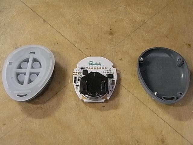
Click to zoom
Application Details
- Equipment Class
- DXX - Part 15 Low Power Communication Device Transmitter
- Date of Grant
- Nov 27, 2012
- Application Purpose
- Original Equipment
- Date of Application
- Nov 27, 2012
- Equipment Note
- Pocket Transmitter
- Frequency Range
- 913.70000000 - 913.70000000
- Company
- Quick S.p.A. unipersonale
- Country
- Italy
Documents & Files
Document Text
Text extracted from the exhibit documents filed with the FCC. Open a document above to read the original.
Users Manual
Manual of installation and use RRC POCKET TRANSMITTER Mode d’installation et d’emploi EMETTEUR DE POCHE RRC GB High Quality Nautical Equipment RRC P902 P904 RADIO REMOTE CONTROL POCKET TRANSMITTER REV 000A PRELIMINARY FR 3 RRC P902/904 - REV000A Pg. 4 CHARACTERISTICS AND OPERATION Pg. 5 MAINTENANCE - battery replacement TECHNICAL DATA INDEX GB P. 6 CARACTÉRISTIQUES ET FONCTIONNEMENT P. 7 ENTRETIEN - remplacement de la batterie CARACTÉRISTIQUES TECHNIQUES SOMMAIRE FR 4 CHARACTERISTICS AND OPERATION GB RRC P902/904 - REV000A RRC POCKET RADIO TRANSMITTER The RCC pocket radio transmitter is a device which combined with a RRC radio receiver is used to control operation of devices or accessories installed on recreational crafts. The RRC radio system is a generic radio control whose failed operation must not cause damage to people, animals or property. The advantages offered by the RRC pocket radio transmitter are: • Microcontroller-operated functions. • Operating temperatures from -15°C to +70°C. • FSK modulation and carrier frequency 913.7 Mhz. • Transmission feedback and low battery indication by means of LED. • Possibility to control more receivers with one transmitter. • Two functions can be activated at the same time. • Floating. INSTALLATION BEFORE USING THE RADIO TRANSMITTER, CAREFULLY READ THIS USER MANUAL. IN CASE OF DOUBTS PLEASE CONTACT THE RETAILER OR QUICK ® CUSTOMER SERVICE. This device was designed and constructed for use on recreational crafts. Other forms of use are not permitted without written authorization from the company Quick ® . Changes or modifications to this unit not expressly approved by the party responsible for compliance could void the user’s authority to operate the equipment. The RRC pocket radio transmitter has been designed and manufactured for the purposes described in this user manual. Quick ® is not liable for direct or indirect damages caused by an improper use of the radio control, due to an incorrect installation or errors possibly present in this manual. THE PACKAGE CONTAINS: pocket radio transmitter with battey included - lanyard - conditions of warranty - the present manual of installation and use. F WARNING: the transmitter needs to be programmed in the receiver’s memory. To do this, follow the procedure shown in the reveiver’s user manual. Power supply The pocket transmitter is powered using a lithium CR2450 battery. To replace it, see the BATTERY REPLACEMENT paragraph. Operational status When any of the transmitter keys is pressed, the green transmission LED flashes quickly and signals that transmission has taken place. It is possible to press up to two keys at the same time, while pressing 3 or more keys simultaneously cancels transmission (transmission LED switched off). Each key pressed corresponds to the activation of a relay on the receiver (see RRC radio receiver manual), which will stay active as long as the key isn’t released. Low battery signal It is recommended to replace the battery within a short period of time if the transmission LED is red during operation. The residual autonomy time depends on the quality of the battery used. Transmission LED Pocket transmitter model P902model P904 F 5 MAINTENANCE - TECHNICAL DATA GB RRC P902/904 - REV000A MODELSP902P904 INPUT CHARACTERISTICS Power supplyCR2450 3V lithium battery Absorption during transmission13 mA CHARACTERISTICS OF THE TRANSMITTER Number of keys2 4 Carrier frequency913.7 Mhz ModulationFSK FCC IDO2W-TXP GENERAL Operating temperaturefrom -15°C to +70°C Dimensions (W x H x D)60 x 47 x 23 mm Weight (including the battery)34 g TECHNICAL DATA QUICK ® RESERVES THE RIGHT TO MODIFY THE TECHNICAL CHARACTERISTICS OF THE EQUIPMENT AND THE CONTENTS OF THIS MANUAL WITHOUT PRIOR NOTICE. TRANSMITTER BASE CR2450 3V LITHIUM BATTERY SCREWS TRANSMITTER FRONT BATTERY HOLDER MAINTENANCE The RRC pocket radio transmitter does not require particular maintenance. Use a soft cloth moistened with water when cleaning it. Do not use chemical or abrasive products. BATTERY REPLACEMENT P902-P904 MODELS WARNING: before operating on the transmitter, make sure that the RRC radio receiver is not powered. Acciden- tally pressing a key may activate the corresponding device and create a dangerous situation. WARNING: danger of explosion if battery is replaced with an other of incorrect type. • Remove the transmitter base by unscrewing the four screws using a Phillips screwdriver. • Remove the battery from the battery holder sliding it outwards with- out using metal tools. • Insert the new battery (of the type indicate in the technical character- istics) paying attention to polarity of the positive pole (+) as shown on the metal battery holder. • Close the transmitter base, checking that it sits correctly in the gasket groove, located on the front of the transmitter, in order to restore the seal. • Tighten the four screws. WARNING: once the transmitter is assembled, verify that the LED does not remain on constantly. If the LED is on, reopen the transmitter and verify that it was assembled correctly. At the end of its useful life, the battery contained in the product must be disposed of separately from other separated urban waste. Dispose of the battery in accordance with the provisions of local law. This device complies with part 15 of the FCC rules. Operation is subject to the following two conditions: 1) This device may not cause harmful interference, and 2) this device must accept any interference received including interference that may cause undesired operation. F 6 CARACTÉRISTIQUES ET FONCTIONNEMENT FR RRC P902/904 - REV000A ATTENTION: l’émetteur doit être programmé dans la mémoire du récepteur. Suivre la procédure indiquée dans le mode d’emploi du récepteur. Alimentation L’émetteur de poche est alimenté par une batterie CR2450 au lithium. Pour la remplacer voir au paragraphe REMPLACEMENT DE LA BATTERIE. Etat de fonctionnement Durant la pression de n’importe quelle touche, la LED de transmission, de couleur verte, c…
Text truncated - open the document above for the full version.
Users Manual
High Quality Nautical Equipment RRC PW94 PT94 RADIO REMOTE CONTROL THRUSTER POCKET TRANSMITTER Manual of installation and use RRC THRUSTER POCKET TRANSMITTER Mode d’installation et d’emploi ÉMETTEUR DE POCHE RRC THRUSTER GB REV 000A PRELIMINARY FR 3 RRC PW94-PT94 - REV000A Pag. 4 CHARACTERISTICS AND OPERATION Pag. 5/6 OPERATION - correspondence between pressed key and activated relay Pag. 7 OPERATION - disabling the transmitter - battery replacement MAINTENANCE - TECHNICAL DATA INDEX GB P. 8 CARACTÉRISTIQUES ET FONCTIONNEMENT P. 9/10 FONCTIONNEMENT - correspondance touche appuyee e relais active P. 11 FONCTIONNEMENT - remplacement de la batterie ENTRETIEN - CARACTÉRISTIQUES TECHNIQUES SOMMAIRE FR 4 CHARACTERISTICS AND OPERATION GB RRC PW94-PT94 - REV000A 1 3 2 4 WARNING: the transmitter needs to be programmed in the receiver’s memory. To do this, follow the procedure shown in the reveiver’s user manual. Power supply The pocket transmitter is powered using a lithium CR2450 battery. To replace it, see the BATTERY REPLACEMENT paragraph. Enabling The RRC Thruster pocket transmitter is enabled by keeping both keys pressed for the PW94 model and 1 2 keys pressed for the PT94 model. Once they have been pressed, the orange transmission LED fi rst starts fl ashing at regular intervals and then starts fl ashing more quickly. After they have been released, the transmission LED will communicate through brief fl ashes that enabling has taken place. Operational status When any of the transmitter keys is pressed, the green transmission LED flashes quickly to signal that transmission has taken place. Each key pressed corresponds to the activation of a relay (or 2 relays) on the receiver, which will stay active as long as the key isn’t released. RRC THRUSTER POCKET RADIO TRANSMITTER The RRC Thruster pocket transmitter is a device which combined with a RRC radio receiver is used to control Quick thrusters installed on recreational crafts. The RRC radio system for thrusters must be used as a supplement to the Quick wired thruster control system already installed on the boat. Take necessary steps in order to avoid that malfunctioning of the RRC Thruster radio control system may cause damage to people, animals or property. The advantages offered by the RRC Thruster pocket radio transmitter are: • Microcontroller-operated functions. • Operating temperatures from -15°C to +70°C. • FSK modulation and carrier frequency 913.7 Mhz. • LED indication of operational status, low battery and transmission feedback. • Floating. INSTALLATION BEFORE USING THE RADIO TRANSMITTER, CAREFULLY READ THIS USER MANUAL. IN CASE OF DOUBTS PLEASE CONTACT THE RETAILER OR QUICK ® CUSTOMER SERVICE. This device was designed and constructed for use on recreational crafts. Other forms of use are not permitted without written authorization from the company Quick ® . Changes or modifications to this unit not expressly approved by the party responsible for compliance could void the user’s authority to operate the equipment. The RRC Thruster pocket radio transmitter has been designed and manufactured for the purposes described in this user manual. Quick ® is not liable for direct or indirect damages caused by an improper use of the radio control, due to an incorrect installation or errors possibly present in this manual. THE PACKAGE CONTAINS: pocket radio transmitter with battery included - lanyard - conditions of warranty - the present manual of installation and use. F Transmission LED Pocket transmitter model PW94model PT94 F 5 OPERATION GB RRC PW94-PT94 - REV000A RRC PW94 Thruster pocket transmitter and RRC R904 radio receiver Pressing the key (anchor ascent) activates relay 1 on the receiver. Pressing the key (anchor descent) activates relay 2 on the receiver. Pressing the two keys simultaneously cancels the transmission. Pressing the key (bow left) activates relay 3 on the receiver. Pressing the key (bow right) activates relay 4 on the receiver. A 2 second transmission delay is introduced when passing from the key (bow left) to the key (bow right) and vice versa. Pressing the two keys simultaneously cancels the transmission. RRC PT94 Thruster pocket transmitter and RRC R904 radio receiver Pressing the 1 key (bow left) activates relay 1 on the receiver. Pressing the 2 key (bow right) activates relay 2 on the receiver. A 2 second transmission delay is introduced when passing from the 1 key (bow left) to the 2 key (bow right) and vice versa. Pressing the two keys simultaneously cancels the transmission. Pressing the 3 key (stern left) activates relay 3 on the receiver. Pressing the 4 key (stern right) activates relay 4 on the receiver. A 2 second transmission delay is introduced when passing from the 3 key (stern left) to the 4 key (stern right) and vice versa. Pressing the two keys simultaneously cancels the transmission. COM SHIELD PROG relay 4relay 3 NO2 NO1 NO4 NO3 V +V- relay 1relay 2 ANT CORRESPONDENCE BETWEEN PRESSED KEY AND ACTIVATED RELAY POCKET TRANSMITTER RRC PT94 THRUSTER RRC R904 RADIO RECEIVERPOCKET TRANSMITTER RRC PW94 THRUSTER 1 3 2 4 6 GB RRC PW94-PT94 - REV000A COM SHIELD PROG relay 1relay 2 relay 3relay 4 relay 5relay 6 relay 8relay 7 relay 10relay 9 relay 12relay 11 NO1 N O 3 N O 5 NO2 NO4 NO6 NO8 NO10 NO12 N O 7 N O 9 N O 1 1 V+V- ANT RRC PW94 Thruster pocket transmitter and RRC R906 radio receiver Pressing the key (anchor ascent) activates relay 1 on the receiver. Pressing the key (anchor descent) activates relay 2 on the receiver. Pressing the two keys simultaneously cancels the transmission. Pressing the key (bow left) activates relay 3 on the receiver. Pressing the key (bow right) activates relay 4 on the receiver. A 2 second transmission delay is introduced when passing from the key (bow left) to the key (bow right) and vice versa. Pressing the two keys simultaneously cancels the transmission. RRC PT94 Thruster pocket transmitter and RRC R906 radio receiver Pressing the 1 key (bow left) activates relay 3 on the recei…
Text truncated - open the document above for the full version.
External Photos
POCKET FAMILY QUICK S.p.A. EXTERNAL PHOTOS PW94 PT94 P904 P902
ID Label/Location Info
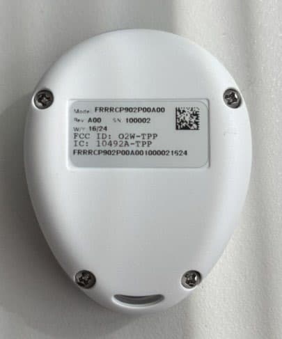
POCKET Label position
Internal Photos
POCKET FAMILY QUICK S.p.A. INTERNAL PHOTOS PW94 PT94 P904 NOTICE: The other side is the same of the models PT94 or PW94 and the external cover shows only two button places to enable the command. P902 NOTICE: The other side is the same of the models PT94 or PW94 and the external cover shows only two button places to enable the command.
Operational Description
OPERATIONAL DESCRIPTION Handheld transmitters The intended use for the transmitters in question are on recreational crafts. The transmitters allow to control the operation, using them in combination with a dedicated receiver, of device or accessories installed on recreational crafts. The family of the handheld transmitters is composed by 5 different types: H902, H904, H912, HT94, HT98. The transmitters have the same electronic board ( the same PCB and components), but change the number/disposition of the buttons. The firmware is the same and factory settable for the five different types of use. The transmission (FSK modulation) takes place in manual mode. For each key press will start the transmission of the frame which correspond the activation of a relay on the receiver. Releasing the button will end the transmission and the corresponding relay will be disabled. Pocket transmitters The intended use for the transmitters in question are on recreational crafts. The transmitters allow to control the operation, using them in combination with a dedicated receiver, of device or accessories installed on recreational crafts. The family of the pocket transmitters is composed by four different types: P902, P904, PW94, PT94. The transmitters have the same electronic board ( the same PCB and components), but change the number/disposition of the buttons. The firmware is the same and factory settable for the five different types of use. The transmission (FSK modulation) takes place in manual mode. For each key press will start the transmission of the frame which correspond the activation of a relay on the receiver. Releasing the button will end the transmission and the corresponding relay will be disabled. Receivers (2-4 relays) The intended use for the receivers in question are on recreational crafts. Allow to control the operation, using them in combination with a dedicated transmitter, of device or accessories installed on recreational crafts. The first family of receivers is composed by 2 different types: R902,R904 (head family). Have the same electronic board ( the same PCB and components), except for the number of relays installed. When receiving a command from a radio transmitter the corresponding relay will be activated. The relay will be disabled when, on the transmitter, the corresponding button will be released. Receivers (6-12 relays) The intended use for the receivers in question are on recreational crafts. Allow to control the operation, using them in combination with a dedicated transmitter, of device or accessories installed on recreational crafts. The second family of receivers is composed by four different types: R906,R908,R910,R912 (head family). Have the same electronic board ( the same PCB and components), except for the number of relays installed. When receiving a command from a radio transmitter the corresponding relay will be activated. The relay will be disabled when, on the transmitter, the corresponding button will be released
Test Report
IMQ S.p.A. con socio unico Via Quintiliano, 43 20138 MILANO - I Test Report No. ARSM00048/2 Date: 2012-08-06 Page 2 of 26 Mod. T RF FCC - C1 /0 T TT T ELECOMMUNICATIONS ELECOMMUNICATIONS ELECOMMUNICATIONS ELECOMMUNICATIONS & && & T TT T ELEMATICS FOR ELEMATICS FOR ELEMATICS FOR ELEMATICS FOR T TT T RANSPORTS RANSPORTSRANSPORTS RANSPORTS L LL L ABORATORY ABORATORYABORATORY ABORATORY 1. GENERAL DATA SAMPLE Samples received on 2012-06-29 (item sent and sampling by applicant) IMQ reference samples BEM 64749 Samples tested No. 1 Object under analysis recognition Not carried out Except where stated, characteristics of products were taken from client description and were not verified by the laboratory TEST LOCATION Testing dates 2012-07-03 ÷ 2012-08-03 Testing laboratory. IMQ S.p.A. - Via Quintiliano, 43 – I-20138 Milano ENVIRONMENTAL CONDITIONING Parameter Measured Ambient Temperature 25 ÷ 35 °C Relative Humidity 50 ÷ 60 % Atmospheric Pressure 900 ÷ 1000 mbar IMQ S.p.A. con socio unico Via Quintiliano, 43 20138 MILANO - I Test Report No. ARSM00048/2 Date: 2012-08-06 Page 3 of 26 Mod. T RF FCC - C1 /0 T TT T ELECOMMUNICATIONS ELECOMMUNICATIONS ELECOMMUNICATIONS ELECOMMUNICATIONS & && & T TT T ELEMATICS FOR ELEMATICS FOR ELEMATICS FOR ELEMATICS FOR T TT T RANSPORTS RANSPORTSRANSPORTS RANSPORTS L LL L ABORATORY ABORATORYABORATORY ABORATORY 2. REFERENCE DOCUMENT DOCUMENT DATE TITLE 47 CFR Part 15 2008 Radio Frequency Device ANSI C63.4 2009 Methods of Measurement of Radio-Noise Emissions from Low-Voltage Electrical and Electronic Equipment in the Range of 9 kHz to 40 GHz ANSI C63.10 2009 American National Standard for Testing Unlicensed Wireless Devices IMQ S.p.A. con socio unico Via Quintiliano, 43 20138 MILANO - I Test Report No. ARSM00048/2 Date: 2012-08-06 Page 4 of 26 Mod. T RF FCC - C1 /0 T TT T ELECOMMUNICATIONS ELECOMMUNICATIONS ELECOMMUNICATIONS ELECOMMUNICATIONS & && & T TT T ELEMATICS FOR ELEMATICS FOR ELEMATICS FOR ELEMATICS FOR T TT T RANSPORTS RANSPORTSRANSPORTS RANSPORTS L LL L ABORATORY ABORATORYABORATORY ABORATORY 3. UNIT UNDER TEST (EUT) DETAILS GENERAL DATA MODEL (basic) Description PW94 Thruster Pocket transmitter with n°4 keys VARIANTS (derived) Description PT94 Thruster Pocket transmitter with n°4 keys P904 Pocket transmitter with n°4 keys P902 Pocket transmitter with n°2 keys FCC ID O2W-TXP Manufacturer QUICK S.p.A. – Via Piangipane, 120/A – 48124 PIANGIPANE (RA) - ITALY Type of equipment THRUSTER POCKET TRANSMITTER Operating frequency: 913,70 MHz Maximum RF radiated power: 89,0 dBμV/m Modulation: FSK Channel Spacing: / Antenna: Integral (on PCB) RX sensitivity: / Main SW identification / Main HW Board identification Peripherals included (for system application) / Interfaces : / Integrated interfaces : / AC adapter: / Data cable / Telecom cable / Power supply type : Internal CR2450 3V Lithium battery AC power input cable : / IMQ S.p.A. con socio unico Via Quintiliano, 43 20138 MILANO - I Test Report No. ARSM00048/2 Date: 2012-08-06 Page 5 of 26 Mod. T RF FCC - C1 /0 T TT T ELECOMMUNICATIONS ELECOMMUNICATIONS ELECOMMUNICATIONS ELECOMMUNICATIONS & && & T TT T ELEMATICS FOR ELEMATICS FOR ELEMATICS FOR ELEMATICS FOR T TT T RANSPORTS RANSPORTSRANSPORTS RANSPORTS L LL L ABORATORY ABORATORYABORATORY ABORATORY DC power input cable : / 4. TEST CONFGURATION OF UNIT UNDER TEST EUT PORTS Port Description Max length Enclosure Plastic surface, closed by 4 metallic screws 60mm. AC power Port not present / DC power Internal CR2450 3V Lithium battery / Earth Port not present / Telecommunication Port not present / Signal Port not present / Control Port not present / Antenna Integral (on PCB) / EUT Antenna Port AC Power Port Earth Port Telecommunication Port Signal/Control Port DC Power Port Enclosure Port IMQ S.p.A. con socio unico Via Quintiliano, 43 20138 MILANO - I Test Report No. ARSM00048/2 Date: 2012-08-06 Page 6 of 26 Mod. T RF FCC - C1 /0 T TT T ELECOMMUNICATIONS ELECOMMUNICATIONS ELECOMMUNICATIONS ELECOMMUNICATIONS & && & T TT T ELEMATICS FOR ELEMATICS FOR ELEMATICS FOR ELEMATICS FOR T TT T RANSPORTS RANSPORTSRANSPORTS RANSPORTS L LL L ABORATORY ABORATORYABORATORY ABORATORY STATE OF THE EUT DURING TESTS Ref. Mode Description #1 Operating Continuous transmission SUPPORT EQUIPMENT Defined as equipment needed for correct operation or loading of the EUT, but not considered as tested: Equipment Manufacturer Model None ELECTROMAGNETICALLY RELEVANT COMPONENTS Component No. Manufacturer Model / RFI SUPPRESSION DEVICES Component No. Manufacturer Model / EMI PROTECTION DEVICES Component No. Manufacturer Model / EUT TECHNICAL DOCUMENTATION Document Reference TX PW94-PT94 - Manual of installation and use Rev 000a TX P902-904 - Manual of installation and use Rev 000a IMQ S.p.A. con socio unico Via Quintiliano, 43 20138 MILANO - I Test Report No. ARSM00048/2 Date: 2012-08-06 Page 7 of 26 Mod. T RF FCC - C1 /0 T TT T ELECOMMUNICATIONS ELECOMMUNICATIONS ELECOMMUNICATIONS ELECOMMUNICATIONS & && & T TT T ELEMATICS FOR ELEMATICS FOR ELEMATICS FOR ELEMATICS FOR T TT T RANSPORTS RANSPORTSRANSPORTS RANSPORTS L LL L ABORATORY ABORATORYABORATORY ABORATORY 5. METHODS OF MEASUREMENT All compliance measurements have been carried out using the procedures described in the standard ANSI C63.4-2009, ANSI C63.10-2009 and Section 15.31 of CFR47 Part 15 – Subpart A (General). Additional test requirements have been adopted according to the reference Section indicated in the § 6 of this test report. FREQUENCY RANGE INVESTIGATED Radiated emission tests: from 0,15 MHz to tenth harmonic of fundamental. IMQ S.p.A. con socio unico Via Quintiliano, 43 20138 MILANO - I Test Report No. ARSM00048/2 Date: 2012-08-06 Page 8 of 26 Mod. T RF FCC - C1 /0 T TT T ELECOMMUNICATIONS ELECOMMUNICATIONS ELECOMMUNICATIONS ELECOMMUNICATIONS & && & T TT T ELEMATICS FOR ELEMATICS FOR ELEMATICS FOR ELEMATICS FOR T TT T RANSPORTS RANSPORTSRANSPORTS RANSPORTS L LL L ABORATORY ABORATORYABORATORY ABORATORY 6. SUMMARY OF TEST RESULTS POSSIBLE TEST CA…
Text truncated - open the document above for the full version.
Contact Information
Applicant
Daniele Padovani
Test Firm
Istituto Italiano del Marchio di Qualita' S.p.A.Eng. Fulvio Giorgi
Technical Specifications
| # | Rule Parts | Frequency Range | Power Output |
|---|---|---|---|
| 1 | 15C | 913.7 MHz - 913.7 MHz | - |
Other Applications from Quick S.p.A. unipersonale
O2W-TPP
Jul 03, 2026RRC Pocket Transmitter
Equipment Class
DXX - Part 15 Low Power Communication Device Transmitter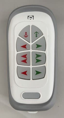
O2W-THP
Jul 03, 2026Handheld TX
Equipment Class
DXX - Part 15 Low Power Communication Device Transmitter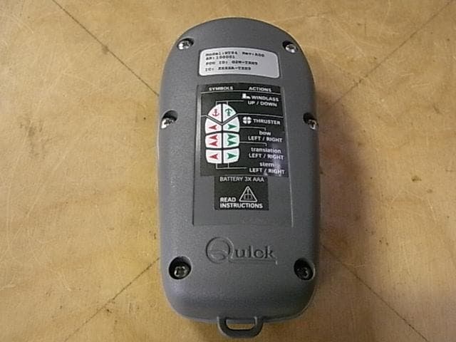
O2W-TXH
Nov 27, 2012Handheld Transmitter
Equipment Class
DXX - Part 15 Low Power Communication Device Transmitter