O2Z-BT1Ambler Bluetooth Module
Intel Corporation
Click to zoom
Application Details
- Equipment Class
- DSS - Part 15 Spread Spectrum Transmitter
- Date of Grant
- Feb 19, 2001
- Application Purpose
- Original Equipment
- Date of Application
- Jun 05, 2000
- Equipment Note
- Ambler Bluetooth Module
- Frequency Range
- 2402.00000000 - 2480.00000000
- Company
- Intel Corporation
- Country
- United States
Documents & Files
Document Text
Text extracted from the exhibit documents filed with the FCC. Open a document above to read the original.
Users Manual
EXHIBIT TT - Response to Item #1 FCC ID O2Z-BT1 1.0 Eligibility Requirements for Regulatory Module Approval As part of Intel’s solution for Bluetooth wireless technology in mobile PCs, Intel will provide regulatory approvals for certain countries in the form of a Module Approval (MA) grant, which can be utilized by PC manufacturers. This section lists the requirements that must be met in order for Intel’s customers to utilize the MA grant. The Intel MA applies only to computer laptop devices. The MA grant is not authorized for any other electronic devices. The Intel Ambler module with Bluetooth wireless technology is a radio device that transmits and receives radio signals in accordance with the spectrum regulations for the 2.4-GHz unlicensed frequency range. Regulatory approval is required for each country throughout the world where the end-user wishes to operate the Ambler module and communicate to other Bluetooth devices. There are two methods by which Intel customers may obtain regulatory approvals for their platform designs: standard type approval for radio transmitters or the MA. The MA is only valid in countries that have accepted the MA process. For countries that have not accepted the MA process, PC manufacturers must submit the laptop for a conventional radio transmitter “type approval” for each country of interest. PC manufacturers may disregard the requirements of this section if they accept the full responsibility for regulatory-type approval of the electronic device with an integrated Ambler module. 1.1 User Guide Information PC manufacturers are required to place specific text in the user’s guide for a notebook PC alongside other regulatory information. The information may be segmented by geographic world region if desired, but the exact text shown below must be maintained. The user’s guide must contain the following items: United States of America Requirements The following text must be copied exactly into the products user’s guide: “This device complies with part 15 of the FCC rules. Operation is subject to the following two conditions: (1) This device may not cause harmful interference, and (2) this device must accept any interference received, including interference that may cause undesired operation. Caution: Changes or modifications not expressly approved by the party responsible for compliance could void the user’s authority to operate the equipment.” General Requirements The following text must be copied exactly into the product’s user’s guide: “This product contains a radio transmitter with Bluetooth wireless technology which has been tested and found to be compliant with the applicable regulations governing a radio transmitter in the 2.400 GHz to 2.4835 GHz frequency range. The countries where this product is authorized for sale and use by Intel are: United States of America Belgium Germany Italy Netherlands Spain Sweden Switzerland United Kingdom Sale or use in any other country is not authorized by Intel and is the sole responsibility of the notebook PC manufacturer.” 1.2 Exterior Laptop Labeling An FCC label, along with specific text, must be placed on the notebook PC that contains an Intel Ambler module with Bluetooth wireless technology. The following exact text must be placed beneath the FCC label on the exterior of the laptop. “Contains one of the Transmitter Modules” FCC ID: To be determined FCC ID: To be determined 1.3 Design Requirements To be eligible to utilize the Intel MA grant, the Intel Ambler module with Bluetooth wireless technology must be designed into the notebook PC following certain design requirements. These requirements are listed below. General The Intel Ambler module with Bluetooth wireless technology may not be altered or modified in any way upon receipt from Intel. Additionally, no external component can be added which changes the radio frequency (RF) characteristics of the transmitted signals. This includes all components both passive and active such as RF filters, RF amplifiers, RF switches, etc. RF components may not be placed between the output pin of the Ambler module and the Intel enabled antennas except the RF transmission line that interconnects them. Antennas Only antennas selected by Intel may be used with the Intel Ambler module with Bluetooth wireless technology. These antennas are designed to be compatible with the RF transmission line impedance and frequency range of the Intel Ambler module with Bluetooth wireless technology. These antennas may not be modified in any way from the design baseline as indicated by the antenna data sheets from the manufacturer. The antennas selected by Intel have been specifically tested with the Intel Ambler module with Bluetooth wireless technology, and they are certified through the regulatory agencies indicated in section 1.1.2 for authorized use. Use of antennas in a platform other than the antennas selected by Intel voids the MA grant for that platform. Transmission Line Interconnection There are specific requirements that must be met when designing a transmission line interconnection between the Intel Ambler module with Bluetooth wireless technology and the antennas. The Intel Ambler module with Bluetooth wireless technology has been specifically designed as a miniature component to be integrated into portable electronic devices. As such the RF connection is not a standard connector, but a ball grid array solder connection. The module should be mounted on a PCB directly or mounted in a specially designed socket that is mounted to a PCB. 1.3.1.1 Impedance The transmission line must be designed to be a 50-Ohm impedance. 1.3.1.2 Physical Implementation [This specific physical implementation of the transmission line interconnection is Intel confidential] 1.4 OEM Regulatory Compliance Instructions The Intel MA may be used by the OEM manufacturers if the manufactures strictly adhere to all items in Sections 1.1 through 1.3. Below are the instructions that must be followed to comply with the…
Text truncated - open the document above for the full version.
Cover Letter(s)
EXHIBIT A – Agent Authorization Letter FCC ID O2Z-BT1
Cover Letter(s)
EXHIBIT H – Request for Confidentiality Letter FCC ID O2Z-BT1 . . . . . . . . . . . . . . . . . . . . . . . . . Int e l Corporation May 24, 2000 Federal Communications Commission Authorization and Evaluation Division 7435 Oakland Mills Road Columbia, Maryland 21046 To whom it may concern, We hereby respectfully request that under the provision of Title 47, paragraph 0.457 of the code that the documents listed below and attached be provided with confidential status. Any exhibit / information for which Intel has requested confidentiality, but which may not be accorded such treatment by the FCC, should be returned to Intel. ♦ Ambler Bluetooth Antenna Information ♦ Ambler Bluetooth Antenna Photos ♦ Ambler Bluetooth Design Guide ♦ Ambler Bluetooth Module frequency block diagram ♦ Ambler Bluetooth Module Schematics ♦ Ambler Bluetooth Processing gain report ♦ Ambler Bluetooth Product Photos, Top and Bottom Sincerely, Rick Jessop Systems Engineer Intel Corporation Mobile Platforms Group 2200 Mission College Blvd. P.O. Box 58119 Santa Clara, CA 95052-8119 408-765-8080 Preeminent building block supplier to the worldwide Internet economy.
Cover Letter(s)
EXHIBIT DD – Cover Letter FCC ID O2Z-BT1 NORTHWEST EMC, INC. 22975 NW Evergreen Parkway, Suite 400 Hillsboro, OR 97124 Dear Application Examiner: On behalf of Intel Corporation, Northwest EMC, Inc is submitting this application for the certification of Intel Corporation’s Bluetooth Ambler module. It operates in the 2.4 – 2.4835 GHz band at a peak output power of 2.33mW. It utilizes both frequency hopping and spread spectrum techniques. This RF module is compliant with Bluetooth Power Class II specifications, and will be used only in personal computers (both in desktop and notebook platforms). The Bluetooth Ambler module can be configured with any one of five antennas. Data is supplied with this application in support of each antenna. The technical report and exhibits demonstrate compliance with FCC rules 47 CFR 15.247, Public Notice DA 00-705, and FCC 97-114. To facilitate the review process, an index of exhibits has been provided (see file “Index of exhibits.pdf”). Your efforts in reviewing this application are greatly appreciated. Best regards, Greg Kiemel Northwest EMC, Inc.
Cover Letter(s)
Exhibits for the FCC application of Intel’s Ambler Bluetooth Spread Spectrum Transmitter FCC ID: EJM-BT1 Exhibit Description File Name Confidential Exhibit A Agent Authorization Letter AgentAuthoizationLetter.pdf Exhibit B Technical Report TechnicalReport.pdf Exhibit C User Guide Ambler Bluetooth® Design Guide.pdf Yes Exhibit D FCC ID Label FCC ID Label.pdf Exhibit E Photos: Product Top and Bottom Ambler Bluetooth® Product Photos Top and Bottom.pdf Yes Exhibit F Photos: Antennas Ambler Bluetooth® Antenna Photos.pdf Yes Exhibit G Schematics Ambler Bluetooth® Module Schematics.pdf Yes Exhibit H Request for Confidentiality Letter RequestforConfidentiality.pdf Exhibit I Frequency Block Diagram Ambler Bluetooth® Module Frequency Block Diagram.pdf Yes Exhibit J Description of Frequency Hopping System Description of Frequency Hopping System.pdf Exhibit K Antenna Information Ambler Bluetooth® Antenna Information.pdf Yes Exhibit L DSS Band Edge Test Data DSS Band Edge.pdf Exhibit M DSS Conducted Spurious Emission Test Data DSS Conducted Spurious Emission.pdf Exhibit N DSS Occupied Bandwidth Test Data DSS Occupied Bandwidth.pdf Exhibit O DSS Output PowerTest Data DSS Output Power.pdf Exhibit P DSS Power Spectral Density Test Data DSS Power Spectral Density.pdf Exhibit Q FHSS 20dB Bandwidth Test Data FHSS 20dB Bandwidth.pdf Exhibit R FHSS Adj. Channel Spacing Test Data FHSS Adj. Channel Spacing.pdf Exhibit S FHSS Band edges Test Data FHSS Band edges.pdf Exhibit T FHSS Conducted Spurious Emissions Test Data FHSS Conducted Spurious Emissions.pdf Exhibit U FHSS Dwell Time Test Data FHSS Dwell Time.pdf Exhibit V FHSS Number of Hopping Frequencies Test Data FHSS Number of Hopping Frequencies.pdf Exhibit W FHSS Output Power Test Data FHSS Output Power.pdf Exhibit X CW Output Power vs DC Input Test Data CW Output Power vs DC Input.pdf Exhibit Y AC Powerline Conducted Emissions Data ACPowerlineConductedEmissions.pdf Exhibit Z Spurious Radiated Emissions Data SpuriousRadiatedEmissions.pdf Exhibit AA Processing Gain Report Ambler Bluetooth® Processing Gain Report.pdf Yes Exhibit BB Test Setup Photos TestSetupPhotos.pdf Exhibit CC Antenna Connection Method AntennaConnectionMethod.pdf Exhibit DD Cover Letter CoverLetter.pdf
Cover Letter(s)
. . . . . . . . . . . . . . . . . . . . . . . . . Int e l Corporation May 24, 2000 Federal Communications Commission Authorization and Evaluation Division 7435 Oakland Mills Road Columbia, Maryland 21046 To whom it may concern, Intel Corporation respectfully requests a regulatory Modular Approval from the Federal Communications Commission for the Intel Ambler Bluetooth module. The exclusive distribution channel for the Intel Ambler module, combined with a Modular Approval, is for sale to laptop computer Original Equipment Manufacturers (OEMs) who will in turn integrate this module into their laptop computer designs. The Intel Ambler module will not be sold to the public for use with the Modular Approval. Consistent with this purpose, Intel is levying design requirements on the laptop manufacturers to ensure that the regulatory requirements are maintained in the OEM platforms with respect to the Bluetooth intentional transmitter module. Sincerely, Rick Jessop Systems Engineer Intel Corporation Mobile Platforms Group 2200 Mission College Blvd. P.O. Box 58119 Santa Clara, CA 95052-8119 408-765-8080 Preeminent building block supplier to the worldwide Internet economy.
Cover Letter(s)
EXHIBIT MM – Response to Item #3 FCC ID O2Z-BT1 NORTHWEST EMC, INC. 22975 NW Evergreen Parkway, Suite 400 Hillsboro, OR 97124 September 7, 2000 Dear Application Examiner: Intel’s Ambler Bluetooth Spread Spectrum Transmitter, FCC ID: EJM-BT1 is seeking FCC authorization as a modular transmitter. The EUT meets the requirements for modular approval as detailed in FCC Public Notice DA00-1407. Compliance to each of the requirements is described below: 1. “The modular transmitter must have its own RF shielding.” The radio portion of the module is contained in its own RF shielding. The shielding is installed at the factory. Please see Exhibit EE for photos of the shielding. 2. “The modular transmitter must have buffered modulation/data inputs.” The EUT has buffered data inputs to insure compliance with Part 15 requirements under conditions of excessive data rates or over-modulation. Please see Exhibit G for schematics of the module. 3. “The modular transmitter must have its own power supply regulation.” The EUT has its own power supply regulation to insure compliance with Part 15 requirements regardless of the quality or level of external DC supplying the module from the host unit. Please see Exhibit G for schematics and Exhibit X for test data demonstrating compliance. 4. “The modular transmitter must comply with the antenna requirements of Section 15.203 and 15.204(c).” The EUT meets the FCC antenna requirements. Please see Exhibit B for the technical report, Exhibit F for photographs of the antennas, Exhibit K for antenna information, Exhibit Z for spurious radiated emissions test data, and Exhibit UU for antenna connection method. 5. “The modular transmitter must be tested in a stand-alone configuration.” The EUT was tested in a stand-alone configuration. Please see Exhibit B for the technical report and Exhibit BB for the test setup photos. Please note that the EUT was also tested for AC Powerline Conducted Emissions (see Exhibit Y). 6. “The modular transmitter must be labeled with its own FCC ID number.” The EUT is labeled with its own FCC ID number. Please see Exhibit D for a drawing of the label and its location on the device. Since the FCC ID number will not be visible when the module is installed inside a host computer, there are instructions given to the OEM on how to apply the exterior label. Please see Section 1.2 of the User Guide (Exhibit TT). 7. “The modular transmitter must comply with any specific rule or operating requirements applicable to the transmitter and the manufacturer must provide adequate instructions along with the module to explain any such requirements.” The EUT is compliant with all applicable FCC rules. Detail instructions for maintaining compliance are given in the User Guide (see Exhibit TT). 8. “The modular transmitter must comply with any applicable RF exposure requirements.” The EUT is compliant with all applicable RF exposure requirements. RF Exposure is addressed in Section 4.5 of the technical report (see Exhibit B). Please contact me if you have additional questions. Your attention to this matter is greatly appreciated. Best regards, Greg Kiemel, Director of Engineering Northwest EMC, Inc.
Cover Letter(s)
EXHIBIT VV - Response to Item #1 FCC ID O2Z-BT1 An Equal Opportunity Employer Intel Corporation 2200 Mission College Blvd Santa Clara, CA 95050 November 6, 2000 Federal Communications Commission Authorization and Evaluation Division 7435 Oakland Mills Road Columbia, Maryland 21046 To whom it may concern, Intel Corporation hereby respectfully requests that under the provision of Title 47, paragraph 0.457 of the code, that the documents listed below and attached to this application be provided with confidential status. Any exhibit / information for which Intel has requested confidentiality, but which may not be accorded such treatment by the FCC, should be returned to Intel. q Ambler Bluetooth Antenna Information.pdf q Ambler Bluetooth Module frequency block diagram.pdf q Ambler Bluetooth Module Schematics.pdf q Revised Ambler Bluetooth Processing Gain_Report.pdf q Ambler Bluetooth Internal Photos.pdf q Summary of Emails between Intel and FCC71.pdf q Supplemental test report11.pdf q Antenna Interconnection Method 11_6_00.pdf The FCC previously denied confidential treatment of the following files: q Ambler Bluetooth Antenna Photos.pdf q Ambler Bluetooth Design Guide.pdf q Ambler Bluetooth Processing gain report.pdf q Ambler Bluetooth Product Photos, Top and Bottom.pdf Intel withdraws its request for confidential treatment of the “Ambler Bluetooth Antenna Photos”, but the other files that were denied confidential treatment should be returned to Intel. Updated versions of those files have been uploaded to the FCC, which do not require confidential treatment. Sincerely, Gordon Chinn Intel Corporation Mobile Platforms Group
Cover Letter(s)
Exhibits for the FCC application of Intel’s Ambler Bluetooth Spread Spectrum Transmitter (updated to include additional items requested by the FCC 7/25/00) FCC ID: O2Z-BT1 Exhibit Description File Name Confidential Exhibit A Agent Authorization Letter AgentAuthorizationLetter.pdf Exhibit B Technical Report TechnicalReport.pdf Exhibit C User Guide Ambler Bluetooth® Design Guide.pdf Yes, return to Intel Exhibit D FCC ID Label FCC ID Label.pdf Exhibit E Photos: Product Top and Bottom Product Photos Top and Bottom.pdf Yes, return to Intel Exhibit F Photos: Antennas Ambler Bluetooth®Antenna Photos.pdf Exhibit G Schematics Ambler Bluetooth® Module Schematics.pdf Yes Exhibit H Request for Confidentiality Letter RequestforConfidentiality.pdf Exhibit I Frequency Block Diagram Ambler Bluetooth®Module Frequency Block Diagram.pdf Yes Exhibit J Description of Frequency Hopping System Description of Frequency Hopping System.pdf Exhibit K Antenna Information Ambler Bluetooth®Antenna Information.pdf Yes Exhibit L DSS Band Edge Test Data DSS Band Edge.pdf Exhibit M DSS Conducted Spurious Emission Test Data DSS Conducted Spurious Emission.pdf Exhibit N DSS Occupied Bandwidth Test Data DSS Occupied Bandwidth.pdf Exhibit O DSS Output PowerTest Data DSS Output Power.pdf Exhibit P DSS Power Spectral Density Test Data DSS Power Spectral Density.pdf Exhibit Q FHSS 20dB Bandwidth Test Data FHSS 20dB Bandwidth.pdf Exhibit R FHSS Adj. Channel Spacing Test Data FHSS Adj. Channel Spacing.pdf Exhibit S FHSS Band edges Test Data FHSS Band edges.pdf Exhibit T FHSS Conducted Spurious Emissions Test Data FHSS Conducted Spurious Emissions.pdf Exhibit U FHSS Dwell Time Test Data FHSS Dwell Time.pdf Exhibit V FHSS Number of Hopping Frequencies Test Data FHSS Number of Hopping Frequencies.pdf Exhibit W FHSS Output Power Test Data FHSS Output Power.pdf Exhibit X CW Output Power vs DC Input Test Data CW Output Power vs DC Input.pdf Exhibit Y AC Powerline Conducted Emissions Data ACPowerlineConductedEmissions.pdf Exhibit Z Spurious Radiated Emissions Data SpuriousRadiatedEmissions.pdf Exhibit AA Processing Gain Report Ambler Bluetooth®Processing Gain Report.pdf Yes, return to Intel Exhibit BB Test Setup Photos TestSetupPhotos.pdf Exhibit CC Antenna Connection Method AntennaConnectionMethod.pdf Exhibit DD Cover Letter CoverLetter.pdf Exhibits - continued Exhibit EE Response to Item #1 AmblerBluetooth® External Photos.pdf Exhibit FF Response to Item #1 AmblerBluetooth® Internal Photos.pdf Yes Exhibit GG Response to Item #1 Revised AmblerBluetooth® Processing Gain_Report.pdf Yes Exhibit HH Response to Item #1 Processing Gain_Report.pdf Exhibit II Response to Item #2 Antenna B Scans.pdf Exhibit JJ Response to Item #2 Antenna C Scans.pdf Exhibit KK Response to Item #2 Antenna D Scans.pdf Exhibit LL Response to Item #2 Antenna E Scans.pdf Exhibit MM Response to Item #3 BT vs Modular Approval Requirements.pdf Exhibit NN Response to Item #4 Intel Emissions tests_11-7-00.pdf Exhibit OO Response to Item #4 NW Emissions tests_11-6-00.pdf Exhibit PP Response to Item #4 Summary of Emails between Intel and FCC71.pdf Yes Exhibit QQ Response to Items #5 & 6 Response to Item 5and6_11-6-00.pdf Exhibit RR Response to Items #5 & 6 supplemental test report1A.pdf Exhibit SS Response to Items #5 & 6 supplemental test report11.pdf Yes Exhibit TT Response to Item #1 User Guide_11-6-00.pdf Exhibit UU Response to Item #4 Antenna Interconnection Method 11_6_00.pdf Yes Exhibit VV Response to Item #1 Revised Request for Confidentiality Letter.pdf
External Photos
EXHIBIT EE – External Photos FCC ID O2Z-BT1
External Photos
EXHIBIT F – Photos: Antennas FCC ID O2Z-BT1
External Photos
EXHIBIT EE – Response to Item #1 FCC ID O2Z-BT1
ID Label/Location Info
EXHIBIT D – FCC ID Label FCC ID O2Z-BT1 ® Page 1 INT RMARC1AA000ES EYWWLLLMMM FCC ID:O2Z-BT1 for RTA # see manual EL INTEL RMARC1AA000ES EYWWLLLMMM FCC ID:TBD for RTA # see manual EL 890XXX 56789 FCC ID: INT 1234567 P1234 XYZ for RTA # see manual INTEL RMARC1AA000ES EYWWLLLMMM FCC ID:TBD for RTA # see manual INTEL -Arial 14pt font, all capitals Pin 1 Marking ~ 1mm diameter Product Code, Lot Number, FCC Code -Arial 5 pt font, all capitals CE marking -gif, ~ 2mm square RTA # info -Arial 2 pt font, mostly lower case On-Module Marking -Schematic SHOWN ACTUAL SIZE
Internal Photos
EXHIBIT WW - Response to Item #1 FCC ID O2Z-BT1
Operational Description
EXHIBIT J – Description of Frequency Hopping System FCC ID O2Z-BT1 The Equipment Under Test (EUT) is the Intel Corporation Ambler Bluetooth module, a spread spectrum transmitter that uses frequency hopping modulation. This device is intended to be sold to Original Equipment Manufacturers (OEMs) for integration into laptop computers. This device will be integrated with one of five Intel sponsored antennas which are being recommended to be used with this device. The module will allow laptop computers to communicate with other consumer electronics containing Bluetooth devices. This will allow a laptop computer to communicate to and share files and data with other devices such as digital cameras, cellular phones, wireless mice, wireless joysticks, wireless keyboards, etc. Within the Bluetooth protocol, frequency hopping is governed by one and only one Bluetooth unit in any given communications group. The master unit determines the pseudo random hopping sequence and conveys this information to other “slave” units that are in the communications group with the master. Because the master unit generates the hopping sequence independently without any external information, there is no coordination with other FHSS systems. The Bluetooth protocol relies on Forward Error Correction (FEC) along with re- transmissions to accommodate for multiple transmitters and interference on specific frequencies. Under two specific modes (page mode and inquiry mode) of the Bluetooth protocol, fewer than 75 hopping frequencies are used for a very short period of time. These two modes are used to search for and acquire new devices in the surrounding area. The amount of time that a Bluetooth device spends in these two modes represents a very small portion of the overall communications time. The data transmitted during these two modes is Direct Sequence modulated. Even though the transmitter is still hopping to a pseudo-random hopping sequence (less than 75 frequencies), the data transmitted at each frequency is Direct Sequence modulated. In this regard, the transceiver qualifies as a Hybrid System under the Part 15.247 rules. Because the Bluetooth protocol contains these modes, and because these modes do not meet the minimum number of hopping channels specified in Part 15.247, the Bluetooth transmitter is categorized as a Hybrid system for these two modes and the hybrid-mode processing gain calculations apply. Because the Bluetooth ? protocol contains these modes, and because these modes do not meet the minimum number of hopping channels specified in Part 15.247 for frequency hopping, the Bluetooth ? transmitter is categorized as a hybrid system for these two modes and the hybrid- mode processing gain calculations apply. Frequency Bands and Channel Arrangement29 November 199919 BLUETOOTH SPECIFICATION Version 1.0 Bpage 19 of 1082 Radio Specification 2 FREQUENCY BANDS AND CHANNEL ARRANGEMENT The Bluetooth system is operating in the 2.4 GHz ISM (Industrial Scientific Medicine) band. In a vast majority of countries around the world the range of this frequency band is 2400 - 2483.5 MHz. Some countries have however national limitations in the frequency range. In order to comply with these national limitations, special frequency hopping algorithms have been specified for these countries. It should be noted that products implementing the reduced frequency band will not work with products implementing the full band. The products implementing the reduced frequency band must therefore be consid- ered as local versions for a single market. The Bluetooth SIG has launched a campaign to overcome these difficulties and reach total harmonization of the frequency band. Channel spacing is 1 MHz. In order to comply with out-of-band regulations in each country, a guard band is used at the lower and upper band edge. GeographyRegulatory RangeRF Channels USA, Europe and most other countries 1) Note 1. Japan, the MPT announced at the beginning of October 1999 that the Japanese frequency band would be extended to 2400-2483.5 MHz, effective immediately. Testing of devices by TELEC may however need some time to change. The previ- ously specified special frequency-hopping algorithm covering 2471-2497 MHz remains as an option. 2.400-2.4835 GHzf=2402+k MHz, k=0,...,78 Spain 2) Note 2. There is a proposal in Spain to extend the national frequency band to 2403- 2483.5 MHz. The Bluetooth SIG has approached the authorities in Spain to get a full harmonization. The outcome is expected by the beginning of year 2000. 2.445-2.475 GHzf=2449+k MHz, k=0,...,22 France 3) Note 3. The Bluetooth SIG has established good contacts with the French authorities and are closely following the development of harmonization. 2.4465-2.4835 GHzf=2454+k MHz, k=0,...,22 Table 2.1: Operating frequency bands GeographyLower Guard BandUpper Guard Band USA2 MHz3.5 MHz Europe (except Spain and France)2 MHz3.5 MHz Spain4 MHz26 MHz France7.5 MHz7.5 MHz Japan2 MHz2 MHz Table 2.2: Guard Bands Physical Channel29 November 199943 BLUETOOTH SPECIFICATION Version 1.0 Bpage 43 of 1082 Baseband Specification 2 PHYSICAL CHANNEL 2.1 FREQUENCY BAND AND RF CHANNELS Bluetooth operates in the 2.4 GHz ISM band. Although globally available, the exact location and the width of the band may differ by country. In the US and Europe, a band of 83.5 MHz width is available; in this band, 79 RF channels spaced 1 MHz apart are defined. In Japan, Spain, and France, a smaller band is available; in this band, 23 RF channels spaced 1 MHz apart are defined. 2.2 CHANNEL DEFINITION The channel is represented by a pseudo-random hopping sequence hopping through the 79 or 23 RF channels. The hopping sequence is unique for the piconet and is determined by the Bluetooth device address of the master; the phase in the hopping sequence is determined by the Bluetooth clock of the master. The channel is divided into time slots where each slot corresponds to an RF hop frequency. Consecutive hops correspond to d…
Text truncated - open the document above for the full version.
Operational Description
EXHIBIT QQ – Response to Items #5 & 6 FCC ID O2Z-BT1 . . . . . . . . . . . . . . . . . . . . . . . . . Int e l Corporation Dear Application Examiner: I. The following is in response to Item 5 of your email to us on 7/25/2000, summarized as follows: “With the device in the acquisition mode, it is a Hybrid transmitter. The dwell time in the acquisition mode was not submitted. Hybrid transmitters must also comply with Section 15.247(a)1. Please address the requirements in this Section. What is the channel separation. How is the hop sequence derived and supply an example of a sequence. How are the frequencies used equally. What is the receiver input bandwidth and how does the receiver synchronize to the acquisition signal?” a) Dwell time in the acquisition mode: Please refer to Figures 4, 5, and 6 for Page Mode operation and Figures 7, 8, and 9 for Inquiry mode operation. These figures are part of the file described as “Supplemental Test Report1A.pdf” which has been forwarded and attached to the application filing for this equipment. An individual transmission on a channel in page mode is 182 microseconds long. During a 12.8 sec time period, the total dwell time on a given channel is 116.5 milliseconds in page mode. In inquiry mode, an individual transmission on a channel is 182 microseconds long. During a 12.8 second time period, the total dwell time on a given channel is 98.5 milliseconds in inquiry mode. The following analyzer settings were used. Span = 0 centered on hopping channel Resolution Bandwidth = 1 MHz Video Bandwidth =Resolution Bandwidth Sweep = as necessary to capture the entire dwell time per hopping channel Detector = peak Trace = max hold b) Channel Separation: Response: By system architecture channels are 1 MHz apart c) Derivation of Hop Sequence: Response: The pseudorandom sequence is generated in a nine-stage shift register whose 5 th and 9 th stage outputs are added in a modulo-two addition stage with the result fed back to the input of the first stage. This produces a pseudorandom sequence length of 31 bits for page and inquiry modes and provides for transition to a 511 bit pseudorandom sequence length for data mode of operation. 2200 Mission College Blvd. P.O. Box 58119 Santa Clara, CA 95052-8119 408-765-8080 Preeminent building block supplier to the worldwide Internet economy. November 6, 2000 Page 2 d) An Example of the Hop Sequence in the hybrid mode: Response: Sequence example a: 5,72,13,48,14,39,54,23,7,46,62,30,3,8,55,10,63,12,16,37,11,43,66,25,51,58,24,17,4 7, 9,29,65 Sequence example b: 41,38,63,14,31,59,40,13,6,25,65,15,61,67,58,47,19,28,54,55,8,48,52,11,5,42,64,17, 62, 51,20,30 e) Equal Use of Frequencies: Response: The FHS (frequency hop selection) packet is transmitted by a sending unit. It contains UAP (upper address part)/LAP (lower address part) as well as clock information which is updated before retransmission in the inquiry state. When in hybrid state, the UAP/LAP is used together with the clock to select the sequence. The output from the selection box constitutes a pseudo-random sequence covering 79 hops for US operation. For inquiry mode, the selection sche…
Text truncated - open the document above for the full version.
Contact Information
Applicant
Christine Ryan(Sr. Certification Engineer)
Technical Contact
Northwest EMC, Inc.Greg V Kiemel
[email protected](503) 844-4066
22975 NW Evergreen Parkway, Suite 400 · Hillsboro, Oregon · United States
Non-Technical Contact
Northwest EMC, Inc.Vicki L Albertson
[email protected](503) 844-4066
Test Firm
Northwest EMC, Inc.Greg Kiemel
Technical Specifications
| # | Rule Parts | Frequency Range | Power Output |
|---|---|---|---|
| 1 | 15C | 2.40 GHz - 2.48 GHz | 2.33 mW |
Other Applications from Intel Corporation

O2Z-EP110
Dec 18, 2014Intel 4.7-inch Smartphone
Equipment Class
JBP - Part 15 Class B Computing Device Peripheral
O2Z-CZ120
Aug 28, 2013HSPA+ Smartphone
Equipment Class
DSS - Part 15 Spread Spectrum Transmitter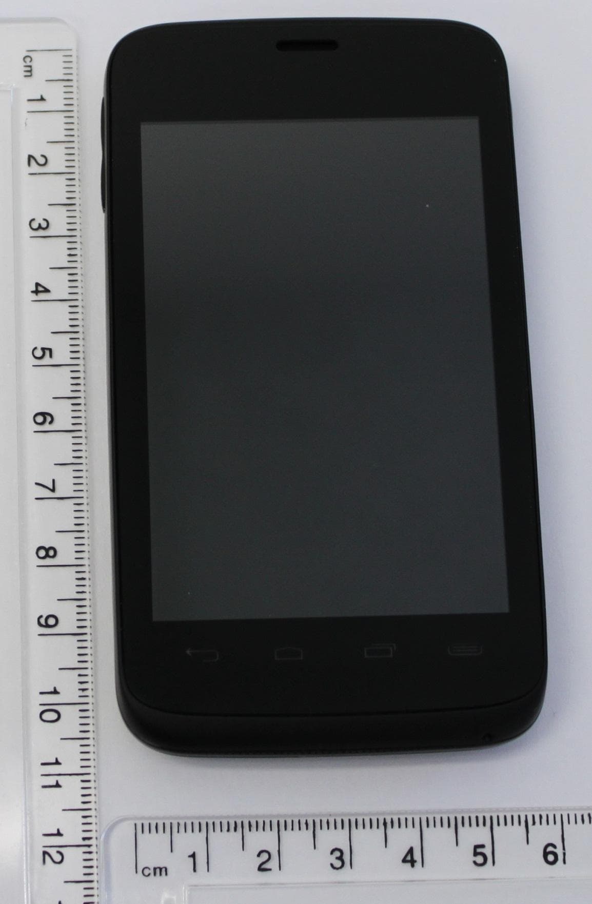
O2Z-BTXZ0
Dec 03, 2012Smartphone
Equipment Class
PCE - PCS Licensed Transmitter held to ear
O2Z-AZ510
Nov 18, 2012ANDROID SMART PHONE
Equipment Class
DSS - Part 15 Spread Spectrum Transmitter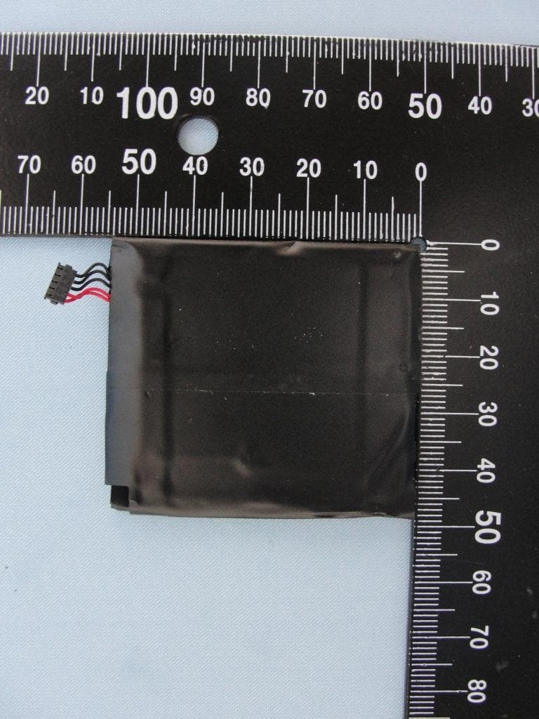
O2Z-AZ210
Sep 06, 2012SMARTPHONE
Equipment Class
NII - Unlicensed National Information Infrastructure TX