O33AR100AR100
Advantra International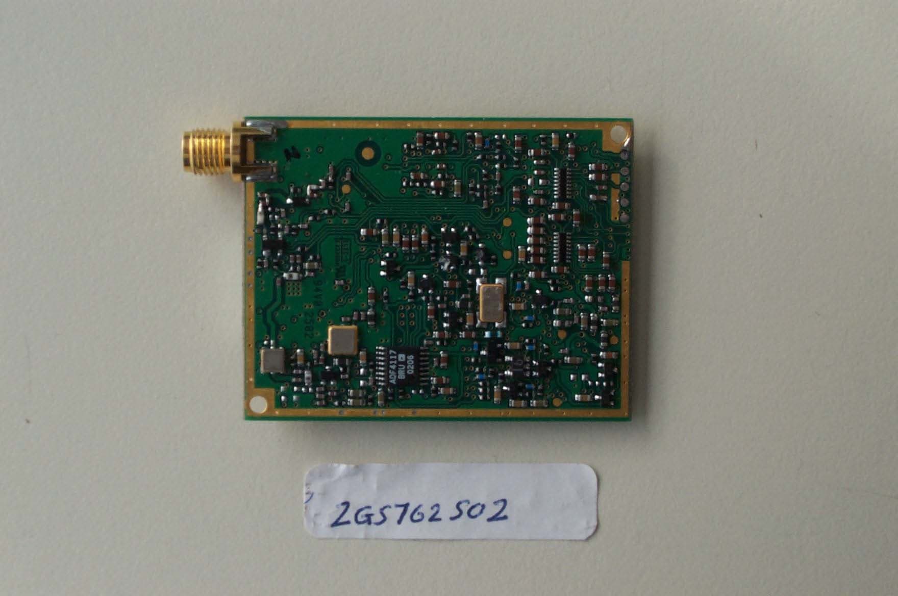
Click to zoom
Application Details
- Equipment Class
- PCB - PCS Licensed Transmitter
- Date of Grant
- Nov 17, 2002
- Application Purpose
- Original Equipment
- Date of Application
- Aug 05, 2002
- Equipment Note
- AR100
- Frequency Range
- 901.00000000 - 902.00000000
- Company
- Advantra International
- Country
- Belgium
Documents & Files
Document Text
Text extracted from the exhibit documents filed with the FCC. Open a document above to read the original.
Users Manual
Advantra International Flanders Language Valley 90 Tel: +32 (0) 57 221711 8900 IEPER Fax: +32 (0) 57 221700 Belgium Advantra International Page 1 of 12 ReFLEX is a trademark of Motorola Inc. Publication ref. PTP 232 Issue 2 User manual The AR100 Advantra International Page 2 of 12 ReFLEX is a trademark of Motorola Inc. Amendment List Amendment No. Date Initials CN Number(s) applicable and Remarks Rev 1 ERRORS AND OMISSIONS The usefulness of this publication depends upon its accuracy. Whilst every endeavour has been made to eliminate errors, some may exist, it is therefore requested that any errors or omissions noted be advised as follows. Please quote: Please send to: (a) Title of publication Advantra International (b) Ref No and issue No. Customer Services Manager (c) Last amendment No received Flanders Language Valley 90 (d) Page and/or Fig No In error 8900 Ieper BELGIUM Advantra International Page 3 of 12 ReFLEX is a trademark of Motorola Inc. Table of Contents 1 PRODUCT DESCRIPTION.............................................................................................................4 2 DEVICE CONFIGURATOR ............................................................................................................5 2.1 Tabsheet ‘TitlePage’ ............................................................................................................... 5 2.2 Tabsheet ‘Customer’ inspection’ ..............................................Error! Bookmark not defined. 2.2.1 Product ID ........................................................................................................................... 6 2.2.2 Build ID................................................................................................................................ 7 2.2.3 Frequency (Hz) ................................................................................................................... 7 2.2.4 Checksum0 & Checksum1 ................................................................................................. 7 2.2.5 Electronic Serial number..................................................................................................... 8 2.2.6 Personal Address................................................................................................................8 2.2.7 Customer reference ............................................................................................................ 8 2.2.8 Read button......................................................................................................................... 8 2.3 Menu item ‘File’ ....................................................................................................................... 9 2.4 Menu item ‘Device’ .................................................................................................................. 9 2.5 Menu item ‘Test’ ...................................................................................................................... 9 2.5.1 Test / Device status ............................................................................................................9 2.5.2 Test / Power calibration .................................................................................................... 11 2.6 Menu item ‘Debug’ ................................................................................................................ 11 2.7 Menu item ‘Serial port’.......................................................................................................... 11 2.8 Menu item ‘Help’.................................................................................................................... 12 Advantra International Page 4 of 12 ReFLEX is a trademark of Motorola Inc. 1 PRODUCT DESCRIPTION The Advantra Model AR100 is a Telemetry module. This product is to be compatible with the so- called 2.7.1.1 requirements of the ReFLEX specifications. The module has two connections. One connection is the antenna port, the other connection is the data port / power supply. The host device will talk to the module over this data port and will instruct to execute some commands. To use the device on a ReFLEX network, the device must be configured and this also happens over this data port. To be able to configure the device, a specific windows application exists. More explanations on that windows application ‘Configurator’ can be found in the sections below. Advantra International Page 5 of 12 ReFLEX is a trademark of Motorola Inc. 2 DEVICE CONFIGURATOR When starting up the software ‘Configurator’ a screen will pop up with a menu bar and two tab sheets. The menu bar has 6 possibilities: File, Device, Test, Debug, Serial Port and Help. The two- tab sheets are Title Page and Customer inspection. In this section all possibilities with this menu’s and tab sheets will be explained. Before operation is possible, check item 2.3 Menu item ‘Device’. 2.1 Tab sheet ‘Customer Inspection’ Depending on who is using the device, a specific configurator exists. There are configurators for development, network providers and services. The functionality of the device doesn’t change but the number of options available is different. (Example, a customer is not allowed to change the ReFLEX address, no one out of development is allowed to change passwords, ...). On the tab sheet ‘Title Page’ info on the type of configurator is given. Advantra International Page 6 of 12 ReFLEX is a trademark of Motorola Inc. In the tab sheet ‘customer inspection’ following items can be found. • Product ID • Build ID • Frequency (Hz) • Checksum0 & Checksum1 • Electronic Serial Number • Personal Address • Customer Reference • Read-button 2.1.1 Product ID The Product ID is a four-character ASCII string identifying the product: This data is “Retrieve” only which means it cannot be reprogrammed. Advantra International Page 7 of 12 ReFLEX is a trademark of Motorola Inc. 2.1.2 Build ID Th…
Text truncated - open the document above for the full version.
Block Diagram
Ref Osc PLL VCO VCO Buffer Tx Buffer PA Switch 884-902MHz SMA LNA 1é Mixer IF1 Filter IF chip IF2 Filter Micro MSBLSB 45MHz 450KHz 929-942MHz 15.15MHz x3 45.45MHz TD0 TD1 TD0 TD1 PSU Vin BLOCK DIAGRAM AR100 RF output: SMA connector Rx Tx
Cover Letter(s)
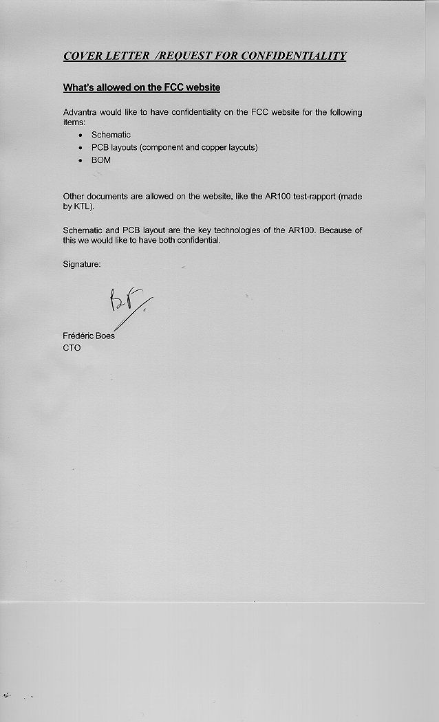
1.) Please resubmit Exhibit 5 the Schematics, they are unreadable. Gary Slater (KTL) has submitted Schematics again on-line (20-09-02). 2.) Please submit a Block Diagram Exhibit 4 per Section 2.1033 of the FCC Rules. Gary Slater (KTL) has submitted Block Diagrams again on-line.(20-09-02) 3.) What are the analyzer settings for the conducted power measurements? Res Bandwidth 3MHz & Video Bandwidth 30 Hz 4.) What are the analyzer settings for the occupied bandwidth plots? Res Bandwidth 300 Hz & Video Bandwidth 300 Hz 5.) What is the emission designator for Section 90.210 (j)? 10KF1D 6.) On page 25 of test report, what rule part did the mask come from? What are the analyzer settings? Rule part 24 Section 24.133(a)(2), Res Bandwidth 300 Hz & Video Bandwidth 300 Hz 7.) Please submit plots showing band edge compliance for Section 24 (901-902 MHz). Plots to follow (should be submitted on-line to the FCC by KTL during the week starting 30-09-02) 8.) What is the emission designator for Section 24? 10KF1D 9.) Please note that the attenuation requirement for radiated spurious emissions is referenced to the desired signal yielding dBc. The attenuation specification is not XX uV/M, or derived from absolute value of the field strength. The dBc is determined from the substitution method such as described in the ANSI/TIA/EIA- 603-A-2001 document. Testing was performed using substitution method, hence results are in terms of ERP in dBm rather than field strength in dBuV/m, is further clarification required?. What is needed is a determination of the actual power levels necessary to reproduce these field strength levels. Those power levels (from a signal generator source and a dipole antenna replacing the EUT) are then compared to the power output of the transmitter to determine dBc. That is the basis of the "substitution method". Please submit data / results obtained in this manner. see above 10.) It is unclear how you did the conducted spurious at the antenna terminal measurement. Please submit a test procedure for this measurement. It appears the substitution signal generator accounts for 20 dB attenuator plus the cable loss Please verify. Conducted spurious emissions were performed by connecting the output of the unit under test into the input of a spectrum analyser via a 20 dB attenuator to prevent overload. At each frequency at which emissions were detected, the equipment under test was substituted with a signal generator tuned to the emission frequency. The level was adjusted to give the same level on the spectrum analyser display as the emission. The signal generator output level was then recorded and compared to the test limit. 11.) What is the maximum gain of the antenna(s) that can be used with this device. The maximum antenna gain is 2.5dBi. 12.) The RF Exposure is unexceptionable. Please resubmit an MPE calculation based on the maximum antenna gain if this device can be used for mobile applications. If this device is used only for fixed applications submit a statement indicating this. Since the device can be mobile or portable SAR measurements will follow. 13.) Is this device used for mobile operations, fixed operations or both? The device is Mobile as well as portable. 14.) You have requested confidentiality. However, there is no letter exhibit requesting confidentiality. Please submit a signed letter requesting confidentiality. Letter should include a list of exhibits to be marked confidential. Letter should include a brief explanation as to why confidentiality is requested. See attachment supplied on-line: Confidential.tif 16.) Provide some antenna installation instructions and RF exposure information in the User's Manual. What antenna(s) will be used with the device? As soon we have done SAR information the user manual will be updated with installation instruction and RF exposure. 17.) Indicate whether the device is capable of operating at the lower output power. Indicate whether the power is switchable between the higher and lower power or variable throughout the range from the highest to the lowest power. Power is switch able over 8 steps, 3dB per step. 18.) Specifically justify use of the device under part 24. What specific Subpart will the device be used for? Justification is that the Equipment operates in the 901 to 902 MHz band and I believe it operates with PCS equipment, and would therefore come under the scope of Subpart D (Narrowband PCS)
Cover Letter(s)
1.) Please resubmit Exhibit 5 the Schematics, they are unreadable. Gary Slater (KTL) has submitted Schematics again on-line (20-09-02). 2.) Please submit a Block Diagram Exhibit 4 per Section 2.1033 of the FCC Rules. Gary Slater (KTL) has submitted Block Diagrams again on-line.(20-09-02) 3.) What are the analyzer settings for the conducted power measurements? Res Bandwidth 3MHz & Video Bandwidth 30 Hz 4.) What are the analyzer settings for the occupied bandwidth plots? Res Bandwidth 300 Hz & Video Bandwidth 300 Hz 5.) What is the emission designator for Section 90.210 (j)? 10KF1D 6.) On page 25 of test report, what rule part did the mask come from? What are the analyzer settings? Rule part 24 Section 24.133(a)(2), Res Bandwidth 300 Hz & Video Bandwidth 300 Hz 7.) Please submit plots showing band edge compliance for Section 24 (901-902 MHz). Plots to follow (should be submitted on-line to the FCC by KTL during the week starting 30-09-02) 8.) What is the emission designator for Section 24? 10KF1D 9.) Please note that the attenuation requirement for radiated spurious emissions is referenced to the desired signal yielding dBc. The attenuation specification is not XX uV/M, or derived from absolute value of the field strength. The dBc is determined from the substitution method such as described in the ANSI/TIA/EIA- 603-A-2001 document. Testing was performed using substitution method, hence results are in terms of ERP in dBm rather than field strength in dBuV/m, is further clarification required?. What is needed is a determination of the actual power levels necessary to reproduce these field strength levels. Those power levels (from a signal generator source and a dipole antenna replacing the EUT) are then compared to the power output of the transmitter to determine dBc. That is the basis of the "substitution method". Please submit data / results obtained in this manner. see above 10.) It is unclear how you did the conducted spurious at the antenna terminal measurement. Please submit a test procedure for this measurement. It appears the substitution signal generator accounts for 20 dB attenuator plus the cable loss Please verify. Conducted spurious emissions were performed by connecting the output of the unit under test into the input of a spectrum analyser via a 20 dB attenuator to prevent overload. At each frequency at which emissions were detected, the equipment under test was substituted with a signal generator tuned to the emission frequency. The level was adjusted to give the same level on the spectrum analyser display as the emission. The signal generator output level was then recorded and compared to the test limit. 11.) What is the maximum gain of the antenna(s) that can be used with this device. The maximum antenna gain is 2.5dBi. 12.) The RF Exposure is unexceptionable. Please resubmit an MPE calculation based on the maximum antenna gain if this device can be used for mobile applications. If this device is used only for fixed applications submit a statement indicating this. Since the device can be mobile or portable SAR measurements will follow. 13.) Is this device used for mobile operations, fixed operations or both? The device is Mobile as well as portable. 14.) You have requested confidentiality. However, there is no letter exhibit requesting confidentiality. Please submit a signed letter requesting confidentiality. Letter should include a list of exhibits to be marked confidential. Letter should include a brief explanation as to why confidentiality is requested. See attachment supplied on-line: Confidential.tif 16.) Provide some antenna installation instructions and RF exposure information in the User's Manual. What antenna(s) will be used with the device? As soon we have done SAR information the user manual will be updated with installation instruction and RF exposure. 17.) Indicate whether the device is capable of operating at the lower output power. Indicate whether the power is switchable between the higher and lower power or variable throughout the range from the highest to the lowest power. Power is switch able over 8 steps, 3dB per step. 18.) Specifically justify use of the device under part 24. What specific Subpart will the device be used for? Justification is that the Equipment operates in the 901 to 902 MHz band and I believe it operates with PCS equipment, and would therefore come under the scope of Subpart D (Narrowband PCS)
Cover Letter(s)
1.) You request confidentiality on Schematics, Schematics are in the test report. Submit a new test report that contains ONLY test report data. Schematics, Users Manual, Board Layouts and Internal Photos should not be in the test report. The test report will be re-issued and downloeaded on-line on the FCC website early next week. (week beginning 07 th October 2002) 2.) Regarding question 17 from your reply, please submit radiated emission measurement for the lowest power setting. We haven't done radiated measurements for the lowest power setting either at KTL or telefication. The only radiated measurements that have been done are at full power, without shielding at KTL and with shielding at telefication. Please note: We have just completed the approval of an almost indetical radio module for Advantra called the AR200 with the FCC (FCC ID: O33AR200, Confirmation Number: EA374558). The AR200 module was also only tested at full power and that was sufficient for the approval. At the time we was approving the AR200 module This was the only question that Joe Dichoso had concerning power levels, I forward you the mail: * Indicate whether the device is capable of operating at the lower output power.Indicate whether the power is switchable between the higher and lower power or variable throughout the range from the highest to lowest power? * Answer: Our product can indeed operate at a lower output power. Switchable between these happens through a command send to the module It is only because we are trying to perform a complete set of records that we did not simply family list the AR100 on the original FCC licence already issued for the AR200. We could have used the same test report to eliminate most further testing on the AR100 but decided to give the module a full assessment and test report. Please can you discuss this application with your colleague Joe Dichoso who technically assessed and licenced the AR200 module. . 3.) What is the conducted power for the lowest power setting? Power = 18dBm ±1.5dB 4.) Submit a External Photos Exhibit that contains ONLY External Photos. See question 5. 5.) Submit a Internal Photos Exhibit that contains ONLY Internal Photos. The device is a Radio Module only, it does not any casing and therefore I cannot submit what you have called External Photos. The photos of the product are simply Track and Component Drawings because the product is effectively a PCB. 6.) Requarding questions 12, 13 and 16 from your reply. This device appears to be licensed module, portable configurations not permitted. We will give approval with SAR in specific host device. We will NOT give approval with SAR for module. For the AR100 our test engineers advised Advantra to perform a calculation on field strength versus distance. We performed these tests and limited the distance between device and body to 20cm. For the approval of the AR200 Advantra limited the distance to 20cm and provided MPE calculations. However, Since the AR100 at the moment can be used closer than 20cm Advantra performed SAR testing at Telefication. I will upload the report for your evaluation in the next few weeks (the values recorded from the AR100 module are very good). Please can you discuss this issue with Joe Dichoso who technically assessed and licenced the AR200 module. Best Regards, Gary Slater Approvals Specialist KTL Saxon Way Priory Park West Kingston upon Hull HU13 9PB UK E-mail: [email protected] Tel: +44(0)1482 801801 Fax: +44(0)1482 801806 Mobile: +44 07802 280 914
Cover Letter(s)
To: Gary Slater, From: Stan Lyles [email protected] FCC Application Processing Branch Re: FCC ID O33AR100 Applicant: Advantra International Correspondence Reference Number: 24121 731 Confirmation Number: EA342125 1.) Regarding question 1 from your reply on 10/3/02. You mention that you will reissue and down load the information on-line on the FCC website early next week. (week beginning October 7, 2002). We have not received this information. Please submit. The new test report has been downloaded on the FCC website today (11-10-02). Test report 2G5762GUS2. 2.) Regarding question 4 and 5 from your reply on 10/3/02. We cannot hold certain pages of an entire exhibit confidentiality unless the entire exhibit is confidential. Please separate confidential material from non-confidential material into separate exhibits. All product drawings and related materials have been removed from the new test report (downloaded today). For all other exhibits that contain pages of confidential material, please take this email as confirmation to hold the entire documents as confidential. 3.) If we do not receive a SAR report, will use the grant condition from EA374558. Depending on SAR report the grant note from EA374558 may still apply. We will be submitting a SAR test report towards the end of next week (anticipated date for download: 17th October 2002) FYI: Regarding question 2 from your reply on 10/03/02. The grantee is responsible for compliance at all power level settings. Data only at full power is sufficient.
Cover Letter(s)
To: Gary Slater, From: Stan Lyles [email protected] FCC Application Processing Branch Re: FCC ID O33AR100 Applicant: Advantra International Correspondence Reference Number: 24132 731 Confirmation Number: EA342125 1.) Regarding question 1 from your reply on 10/3/02 and 10/11/02 appears to be the same test report as the original test report. Submit a new test report that contains ONLY TEST REPORT DATA. Schematics, Users Manual, Board Layouts and Internal Photos SHOULD NOT BE IN THE TEST REPORT per your request for confidentiality. The amended KTL test report (Ref: 2G5762GUS2) has been downloaded on the FCC website. All product drawings and related materials have been removed from the new test report with the exception of some pictures which are required in the test report for product identification purposes and cannot be removed. (new test report downloaded today) 2.) Regarding question 2 from 10/11/02 and question 4 and 5 from 10/3/02 has the same information as question 1. For all other exhibits that contain pages of confidential material, please take this email as confirmation to hold the entire documents as confidential. NOTE: Please do not respond to any questions until you have answered all questions including SAR test report. The SAR test report (in 3 parts) has been downloaded on the FCC website today. The items indicated above must be submitted before processing can continue on the above referenced application. Failure to provide the requested information within 60 days of the original e-mail date may result in application dismissal pursuant to Section 2.917 (c) and forfeiture of the filing fee pursuant to section 1.1108. DO NOT reply to this e-mail by using the Reply button. In order for your response to be processed expeditiously, you must upload your response via the Internet at www.fcc.gov, Electronic Filing, OET Equipment Authorization Electronic Filing. If the response is submitted through Add Attachments, in order to expedite processing, a message which informs the processing staff that a new exhibit has been submitted must also be submitted via Submit Correspondence. Also, please note that partial responses increase processing time and should not be submitted. Any questions about the content of this correspondence should be directed to the e-mail address listed below the name of the sender.
Cover Letter(s)
To: Gary Slater, From: Stan Lyles [email protected] FCC Application Processing Branch Re: FCC ID O33AR100 Applicant: Advantra International Correspondence Reference Number: 24172 731 Confirmation Number: EA342125 1) Regarding correspondence reference numbers 24121 and 24132, we did not find an updated report in the exhibits. Both the new KTL report for the AR100 (with all product information removed except photographs of the product which are required for identification purposes) and the new SAR test report has been downloaded on the FCC website (Downloaded on the 18-10- 02.) These test reports can be found in the exhibit section on the FCC website. The items indicated above must be submitted before processing can continue on the above referenced application. Failure to provide the requested information within 60 days of the original e-mail date may result in application dismissal pursuant to Section 2.917 (c) and forfeiture of the filing fee pursuant to section 1.1108. DO NOT reply to this e-mail by using the Reply button. In order for your response to be processed expeditiously, you must upload your response via the Internet at www.fcc.gov, Electronic Filing, OET Equipment Authorization Electronic Filing. If the response is submitted through Add Attachments, in order to expedite processing, a message which informs the processing staff that a new exhibit has been submitted must also be submitted via Submit Correspondence. Also, please note that partial responses increase processing time and should not be submitted. Any questions about the content of this correspondence should be directed to the e-mail address listed below the name of the sender.
Cover Letter(s)
To: Gary Slater, From: Stan Lyles [email protected] FCC Application Processing Branch Re: FCC ID O33AR100 Applicant: Advantra International Correspondence Reference Number: 24290 731 Confirmation Number: EA342125 1.) Please submit new internal photos with shield remove in the Internal Photos Exhibit. Mark this confidential as requested (PCB Layouts). I have downloaded new pictures on the FCC website under Exhibits (PCB Layout) The items indicated above must be submitted before processing can continue on the above referenced application. Failure to provide the requested information within 60 days of the original e-mail date may result in application dismissal pursuant to Section 2.917 (c) and forfeiture of the filing fee pursuant to section 1.1108. DO NOT reply to this e-mail by using the Reply button. In order for your response to be processed expeditiously, you must upload your response via the Internet at www.fcc.gov, Electronic Filing, OET Equipment Authorization Electronic Filing. If the response is submitted through Add Attachments, in order to expedite processing, a message which informs the processing staff that a new exhibit has been submitted must also be submitted via Submit Correspondence. Also, please note that partial responses increase processing time and should not be submitted. Any questions about the content of this correspondence should be directed to the e-mail address listed below the name of the sender.
Cover Letter(s)
To: Gary Slater, From: Stan Lyles [email protected] FCC Application Processing Branch Re: FCC ID O33AR100 Applicant: Advantra International Correspondence Reference Number: 24290 731 Confirmation Number: EA342125 1.) Please submit new internal photos with shield remove in the Internal Photos Exhibit. Mark this confidential as requested (PCB Layouts). I have downloaded new pictures on the FCC website under Exhibits (PCB Layout) The items indicated above must be submitted before processing can continue on the above referenced application. Failure to provide the requested information within 60 days of the original e-mail date may result in application dismissal pursuant to Section 2.917 (c) and forfeiture of the filing fee pursuant to section 1.1108. DO NOT reply to this e-mail by using the Reply button. In order for your response to be processed expeditiously, you must upload your response via the Internet at www.fcc.gov, Electronic Filing, OET Equipment Authorization Electronic Filing. If the response is submitted through Add Attachments, in order to expedite processing, a message which informs the processing staff that a new exhibit has been submitted must also be submitted via Submit Correspondence. Also, please note that partial responses increase processing time and should not be submitted. Any questions about the content of this correspondence should be directed to the e-mail address listed below the name of the sender.
Cover Letter(s)
To: Gary Slater, From: Stan Lyles [email protected] FCC Application Processing Branch Re: FCC ID O33AR100 Applicant: Advantra International Correspondence Reference Number: 24326 731 Confirmation Number: EA342125 1.) Please submit new internal photos with shield remove in the Internal Photos Exhibit. Mark this confidential as requested (PCB Layouts). I have downloaded new internal picture (with shielding off) today on the FCC website The items indicated above must be submitted before processing can continue on the above referenced application. Failure to provide the requested information within 60 days of the original e-mail date may result in application dismissal pursuant to Section 2.917 (c) and forfeiture of the filing fee pursuant to section 1.1108. DO NOT reply to this e-mail by using the Reply button. In order for your response to be processed expeditiously, you must upload your response via the Internet at www.fcc.gov, Electronic Filing, OET Equipment Authorization Electronic Filing. If the response is submitted through Add Attachments, in order to expedite processing, a message which informs the processing staff that a new exhibit has been submitted must also be submitted via Submit Correspondence. Also, please note that partial responses increase processing time and should not be submitted. Any questions about the content of this correspondence should be directed to the e-mail address listed below the name of the sender.
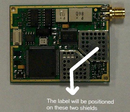
ID Label/Location Info
LABEL INFO : AR100 FCC ID : O33AR100 TESTED TO COMPLY WITH FCC STANDARD FOR PART 2, PART 15, PART 24 AND PART 90 ||||||||||||||||| 12A57 FREQUENCY: 929.6625 Mhz REFLEX ADDRESS: 0018998472
RF Exposure Info
RF EXPOSURE / ENVIRONMENTAL EVALUATION Normal Operating Conditions Temperature -20°C to +60 0 C (-4 0 F to + 140 0 F) Ambient Relative Humidity 20 to 75% Supply Voltage V +/- 5% Extreme Operating Conditions Temperature -40 0 C to +85 0 C (-40 0 F to +185 0 F) Ambient Relative Humidity 75to 95 % (Non Condensing)
RF Exposure Info
TTI-P-G 158 DASY Test-Report, Advantra_ 6575_262_SAR Distribution Plots Page 1 of 14 Appendix for the Report Dosimetric Assessment of the Advantra AR100 (FCC ID: O33AR100) According to the FCC Requirements SAR Distribution Plots October 04, 2002 IMST GmbH Carl-Friedrich-Gauß-Str. 2 D-47475 Kamp-Lintfort Customer Advantra International Flanders Language Valley 90 B-8900-Ieper The test results only relate to the items tested. This report shall not be reproduced except in full without the written approval of the testing laboratory. dasy_report_fcc_supplement_c _2.0.doc/25.09.2001/CH DASY Test-Report, Advantra_ 6575_262_SAR Distribution Plots Page 2 of 14 dasy_report_fcc_supplement_c _2.0.doc/25.09.2001/CH Table of Contents 1 SAR DISTRIBUTION PLOTS, TEST SIDE AMBIENT CONDITION. ..................................................... 3 2 SAR DISTRIBUTION PLOTS, 900 MHZ ...................................................................................................... 4 3 SAR Z-AXIS SCAN (VALIDATION) ...................…
Text truncated - open the document above for the full version.
Contact Information
Applicant
Bernard Vandekerckhove(Chief Executive Officer)
Technical Contact
Non-Technical Contact
KTLGary Slater
[email protected]+44 1482 801801
Test Firm
KTLMark Render
Technical Specifications
| # | Rule Parts | Frequency Range | Power Output | Emission | Tolerance |
|---|---|---|---|---|---|
| 2 | 24D | 901 MHz - 902 MHz | 1.8 W | 10K0F1D | 1 ppm |
Other Applications from Advantra International
O33AR200
Aug 29, 2002TNB - Licensed Non-Broadcast Station Transmitter
Equipment Class
TNB - Licensed Non-Broadcast Station Transmitter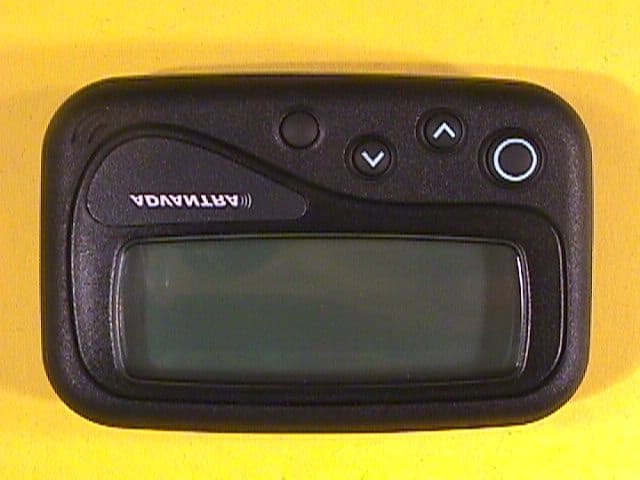
O33AR1800
Sep 27, 20004 Line Alphanumeric ReFlex Pager
Equipment Class
PCT - PCS Licensed Transmitter worn on body