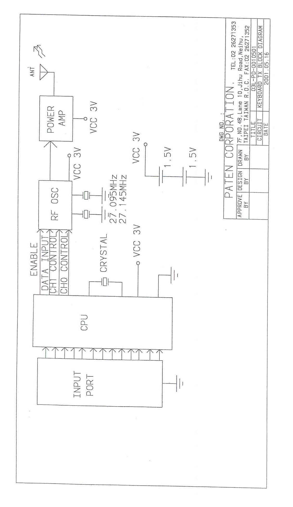
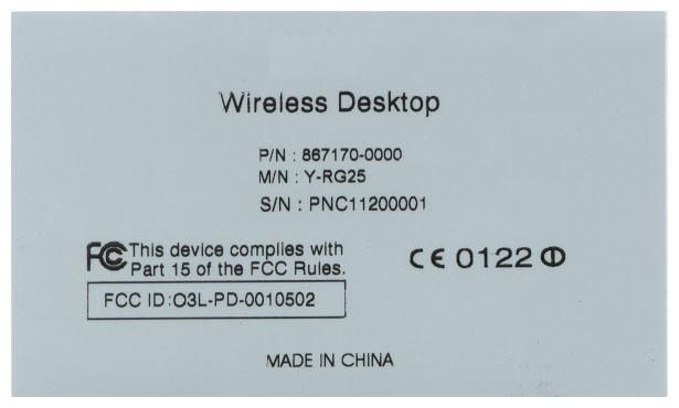
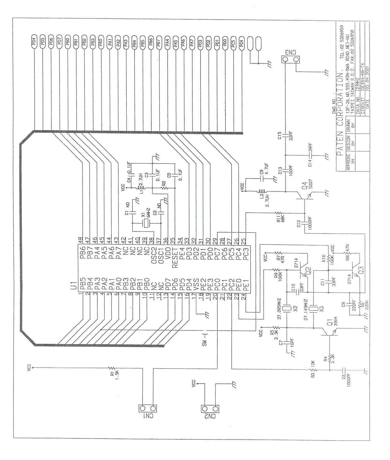
O3L-PD-0010502Wireless Keyboard
Paten Wireless Technology Inc.
Click to zoom
Application Details
- Equipment Class
- DXX - Part 15 Low Power Communication Device Transmitter
- Date of Grant
- Aug 01, 2001
- Application Purpose
- Original Equipment
- Date of Application
- Aug 01, 2001
- Equipment Note
- Wireless Keyboard
- Frequency Range
- 27.09500000 - 27.14500000
- Country
- Taiwan
Documents & Files
Document Text
Text extracted from the exhibit documents filed with the FCC. Open a document above to read the original.
Users Manual
Wireless Desktop Users Guide Table of Contents Important Ergonomic Information2 Introduction to the Wireless Desktop2 The Wireless Mouse2 The Wireless Keyboard2 Package Checklist2 Installation of the Wireless Desktop3 Switching Channels3 Low Battery Lights3 Driver & Utilities Installation3 Wireless Mouse Utility Program4 Scrolling Functions4 3rd Button Functionality4 Keyboard Multi-Media key assignments4 Maintenance of your Wireless Desktop5 Installation Configuration and Troubleshooting5 User Informaton6 2 Important Ergonomic Information Long periods of repetitive motions using an improperly set-up workspace, incorrect body position, and poor work habits may be associated with physical discomfort and injury to nerves, tendons, and muscles. If you feel pain, numbness, weakness, swelling, burning, cramping, or stiffness in these areas, see a qualified health professional. Introduction to the Wireless Desktop The Wireless Desktop is loaded full of features. A wireless 3-button wheel mouse and a wireless 112 key multi-media keyboard connect to your computer with a single receiver using RF (Radio Frequency) technology. This custom designed receiver can accept signals up to 1.2 meters (3.5 feet) away. We have included all the batteries you need to get started. Battery life will depend greatly on the amount of usage but you can expect in excess of 2-6 months. The Wireless Mouse This 2-channel 3-button wheel mouse uses the latest RF technology to bring you unprecedented performance and value. Using the included mouse driver you may program your mouse wheel to perform many commonly used functions. The Wireless Keyboard This 2-channel 103 key keyboard comes loaded with 9 extra multi-media keys that are specifically designed to enhance your Internet and Media experiences. These 9 keys come pre-programmed to perform many common functions. Package Checklist • Wireless Keyboard• Wireless Mouse • Wireless Receiver• Driver Disk for Mouse and Keyboard • 4 - AAA Batteries• User’s Guide • Hardware Product Warranty 3 Installation of the Wireless Desktop Make sure that your computer is powered off before plugging the receiver into the PS/2 mouse and keyboard ports located in the rear of your computer. Install the included batteries into the mouse and keyboard before turning on the system. Depending on your operating system you may be prompted to insert the driver disk into computer’s drive, Insert the included driver disk and follow the on-screen instructions. Switching Channels Channels allow more than one wireless device to be used at a time. An ID code allows more than one of the same type of device to be attached at the same time. If you find that you are having problems with your mouse or keyboard (erratic or no movement) simply select the channel by pressing the reset key on the receiver and then the reset button on the keyboard and or mouse. This will automatically switch the channel and ID code and keyboard and or mouse will work correctly. Low Battery Lights If the light in the front of the mouse or the top left of the keyboard does not go on when you move the mouse or press a key, the voltage of the battery is low. Please replace your batteries. Expected battery life is 2 to 6 months depending on usage. Driver & Utilities Installation The utilities program can be used to install the mouse and keyboard customization driver, this adds additional programmability to your mouse buttons and the multimedia keys of the keyboard. After the proper installation of the hardware, insert the program driver disk into the disk drive, and double click on the “SETUP” icon to start the installation. Follow the on screen prompts to finish the installation, which may or may not ask you to restart your computer (dependent on your operating system). 4 Wireless Mouse Utility Program The utility program uses your normal “Mouse Control Panel”. This addition adds two sets of tabs to the menus (“Wheel” and Buttons”). For additional help with all “Mouse Control Panel” items use the help buttons located in the menus. Scrolling Functions These controls enable and disable smooth scrolling and the number of lines to scroll at a time. See the Details button for more information. 3rd Button Functionality These controls support the functions of the middle wheel button. The available controls are outlined here. See the Help button for more details. • Universal Scroll - Allows you to change the scrolling style and speeds of the mouse wheel. • Zooming - Magnify a section of your screen for easier viewing of small text and graphics. • Auto Scroll - Program the screen to scroll by the direction of mouse movement. • Vertical Wheel Cooperate Functions - This provides 3 types of additional functions to the scroll wheel including; zoom, shift lock, and switch from vertical to horizontal scrolling. • Other Functions - Among these additional functions are “Backspace”, “F1”, and “Delete” plus activation of other special functions of Windows and Explorer. Keyboard Multi-Media key assignments • Refresh – Refreshes the currently displayed web page • Bookmark – Adds the current Web page to your Favorites List • Search – Opens your systems default Search Page • Mail – Opens your systems default E-mail application • Internet - Opens your system default Internet Browser • Play/Pause - Starts and stops the playback of your Audio and Video applications • Volume Up - Increases your system volume • Volume Down - Decreases your system volume 5 • Volume Mute - Mutes your system volume Maintenance of your Wireless Desktop • If the mouse does not move smoothly, you should clean the roller ball and the roller bars in the mouse. • Open the cover of the ball by turning it counter-clockwise, remove the ball and wipe it with a clean cloth. • There are three sets of roller bars. Remove the dust or any other miscellaneous matter by using a cotton swab. You can dip the cotton swab in alcohol to help remove deposits if necessary. • You may clean the surface of the Mou…
Text truncated - open the document above for the full version.
Cover Letter(s)
From: Mike Kuo Sent: Friday, July 27, 2001 12:07 PM To: 'tai-cheng huang' Subject: RE: Paten Wireless Technology Inc.,FCC ID:O3L-PD-0010502,AN01T1422 Dear Mr. Huang: Your reply to question #1: Loop antenna has to be used to measure Field Strength below 30MHz. This requirement has not been changed by FCC. The FCC ID number you referenced is a mistake made by FCC. If I use the previous granted application to request FCC to explain why the application was granted on last year can use biconilog antenna for below 30 MHz measurement, that application will be dismissed or request you to provide additional technical data. Even though your biconilog antenna can be calibrated below 30 MHz, FCC will not accept the test data with biconilog for below 30MHz measurement. This is not the first time that test lab try to use biconilog for below 30 MHz measurement, FCC rejected every time. As result, my number 1 question still remains unchanged. Your reply to Question #4: The request for bandwidth plot is not to show the field strength requirements to 15.209 requirements. You have provided spurious emission data already. The purpose to request bandwidth plot is to make sure the bandwidth of fundamental frequency is not felled into the restricted band as indicated in 15. 205(a). This is one of items that FCC requires all TCB to make the spectrum plot is provided within the application. As result, my questions #2 remains unchanged. Best Regards Mike Kuo / TCB Certifier -----Original Message----- From: tai-cheng huang [mailto:[email protected]] Sent: Friday, July 27, 2001 9:23 AM To: [email protected] Subject: RE:Paten Wireless Technology Inc.,FCC ID:O3L-PD-0010502,AN01T1422 Dear Mike Kuo: I am the EMI test engineer of FCC ID:O3L-PD-0010502 application. My name is Tai cheng huang .Thank you for your e-mail of July 25,2001.I knew it from Joe hsieh.I would like to confirm Question#1 ,Question#4. Question#1:As test report indicated,there is no loop antenna was used during the tests.Since the fundamental frequency is below 30 MHz,loop antenna has to be used for below 30 MHz measurements.Please submit new test data,setup photo,and measuring antenna information. Reply:I used biconilog antenna(Schwarzbeck,model:9160) for the fundamental emission in the measurement, because it can be used in the frequency range from 25 MHz to 2000 MHz.Last year we have applied for another similar wireless mouse FCC ID:O3LPT-2000- 6789and have got the grant. Question#4:Please sumit a bandwith plot to show bandedge compliance. Reply:According to 15.227(b) The field strength of any emission which appear outside of this band shall not exceed the general radiated emission limit in 15.209,there is no bandwidth requirement.Do you mean to ensure the outband emission meet 15.209 requirement? Your prompt reply will be most appreciated.Thank you. Sincerely yours, Tai cheng huang mailto:[email protected] and [email protected] EMI test engineer of EMC Department Electronics Testing Center,Taiwan
Test Report
FCC ID. :O3L-PD-0010502 Rev. No 1.0 FCC Part 15 Subpart C EMI TEST REPORT of E.U.T. : Transmitter of Cordless Keyboard FCC ID. : O3L-PD-0010502 MODEL : Y-RB25 Working Frequency : 27.000 MHz for APPLICANT: Paten Technology Corporation. ADDRESS: 7F. NO.48, Lane 10, Jihu Road, Neihu, Taipei 114, Taiwan, R.O.C. Test Performed by ELECTRONICS TESTING CENTER, TAIWAN NO. 8 LANE 29, WENMIMG ROAD, LOSHAN TSUN, KWEISHAN HSIANG, TAOYUAN, TAIWAN, R.O.C. Tel:(03)3276170-3276174 Fax:(03)3276188 Report Number : ET90S-04-038-03 ETC Report No.:ET90S-04-038-03FCC ID.: O3L-PD-0010502 Rev. No 1.0 TEST REPORT CERTIFICATION Applicant: Paten Technology Corporation. 7F. NO.48, Lane 10, Jihu Road, Neihu, Taipei 114 , Taiwan, R.O.C. Manufacturer: Paten Technology Corporation. 7F. NO.48, Lane 10, Jihu Road, Neihu, Taipei 114 , Taiwan, R.O.C. Description of EUT: a) Type of EUT: Transmitter of Cordless Keyboard b) Trade Name: Dexxa, Labtec c) Model No.: Y-RB25 d) FCC ID: O3L-PD-0010502 e) Working Frequency: 27.000 MHz f) Power Supply: DC 3V Battery Regulation Applied: FCC Rules and Regulations Part 15 Subpart C (1999) I HEREBY CERTIFY THAT; The data shown in this report were made in accordance with the procedures given in ANSI C63.4 and the energy emitted by the device was founded to be within the limits applicable. I assume full responsibility for accuracy and completeness of these data. Note : 1. The results of the testing report relate only to the items tested. 2. The testing report shall not be reproduced except in full, without the written approval of ETC. Test Date : Apr. 27, 2001 Test Engineer : Approve & Authorized Signer : Win-Po Tsai, Manager, NVLAP Signatory EMC Dept. I of ELECTRONICS TESTING CENTER, TAIWAN ETC Report No.:ET90S-04-038-03FCC ID.: O3L-PD-0010502 Rev. No 1.0 Table of Contents Page 1. GENERAL INFORMATION............................................................................................................................................................1 1.1 PRODUCT DESCRIPTION...................................................................................................................................................................1 1.2 CHARACTERISTICS OF DEVICE:.......................................................................................................................................................1 1.3 TEST METHODOLOGY......................................................................................................................................................................1 1.4 TEST FACILITY..................................................................................................................................................................................1 2. DEFINITION AND LIMITS..............................................................................................................................................................2 2.1 DEFINITION........................................................................................................................................................................................2 2.2 RESTRICTED BANDS OF OPERATION.............................................................................................................................................2 2.3 LIMITATION.......................................................................................................................................................................................2 2.4 LABELING REQUIREMENT...............................................................................................................................................................3 2.5 USER INFORMATION.........................................................................................................................................................................3 3 SYSTEM TEST CONFIGURATION................................................................................................................................................4 3.1 JUSTIFICATION..................................................................................................................................................................................4 3.2 DEVICES FOR TESTED SYSTEM.......................................................................................................................................................4 4 RADIATED EMISSION MEASUREMENT......................................................................................................................................5 4.1 APPLICABLE STANDARD.................................................................................................................................................................5 4.2 MEASUREMENT PROCEDURE..........................................................................................................................................................5 4.3 TEST DATA.........................................................................................................................................................................................7 4.4 FIELD STRENGTH CALCULATION..................................................................................................................................................8 4.5 RADIATED TEST EQUIPMENT.........................................................................................................................................................8 4.6 MEASURING INSTRUMENT SETUP.................................................................................................................................................9 4.7 RADIATED MEASUREMENT PHOTOS.............................................................................................................................................9 5. CONDUCTED EMISSION MEASUREMENT............................................................................................…
Text truncated - open the document above for the full version.
Contact Information
Applicant
Jon Liao(R&D Manager)
Test Firm
Electronics Testing Center, TaiwanWill Yauo
Technical Specifications
| # | Rule Parts | Frequency Range | Power Output |
|---|---|---|---|
| 1 | 15C | 27.095 MHz - 27.145 MHz | - |
Other Applications from Paten Wireless Technology Inc.

O3L-PT61R001
Oct 03, 2007WIRELESS OPTICAL LIPSTICK MOUSE
Equipment Class
DXT - Part 15 Low Power Transceiver, Rx Verified
O3L-PT-03-K4D
Oct 29, 200627MHz Wireless Optical Desktop
Equipment Class
DXX - Part 15 Low Power Communication Device Transmitter
O3L-PT2005-MH2
Sep 20, 2006Wireless Laser Mouse
Equipment Class
DXX - Part 15 Low Power Communication Device Transmitter
O3L-PT2005-MH
May 02, 2006Labtec Wireless Laser Mouse for Notebooks
Equipment Class
DXX - Part 15 Low Power Communication Device Transmitter
O3L-PT2005-MF
Apr 27, 2006Wireless Laser Mouse
Equipment Class
DXX - Part 15 Low Power Communication Device Transmitter