O3U630211TXWireless Audio Player
Playmates Asia Services Limited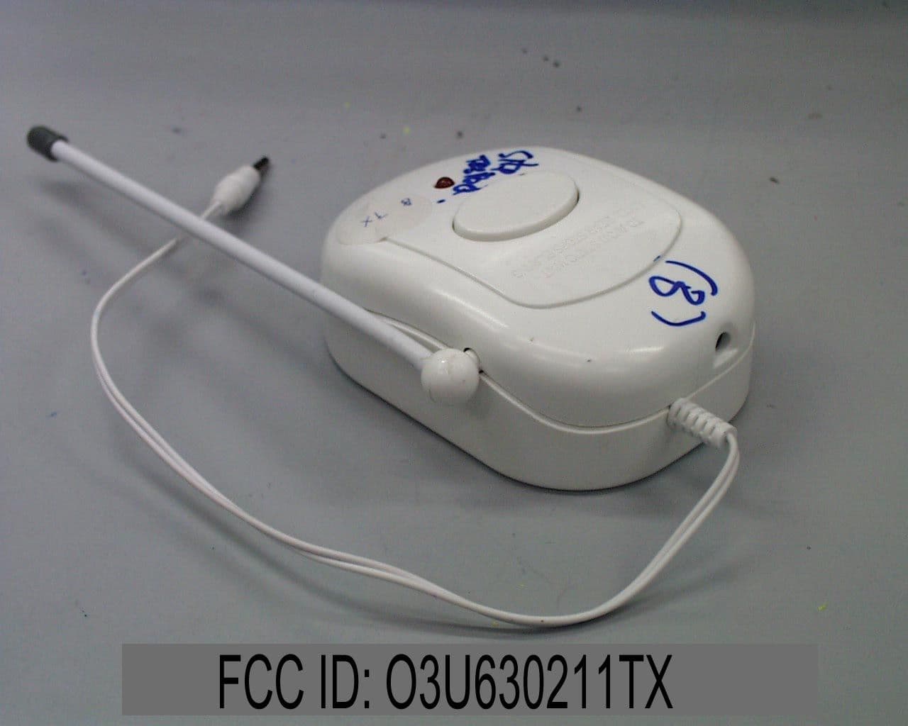
Click to zoom
Application Details
- Equipment Class
- DXT - Part 15 Low Power Transceiver, Rx Verified
- Date of Grant
- Nov 13, 2001
- Application Purpose
- Original Equipment
- Date of Application
- Nov 13, 2001
- Equipment Note
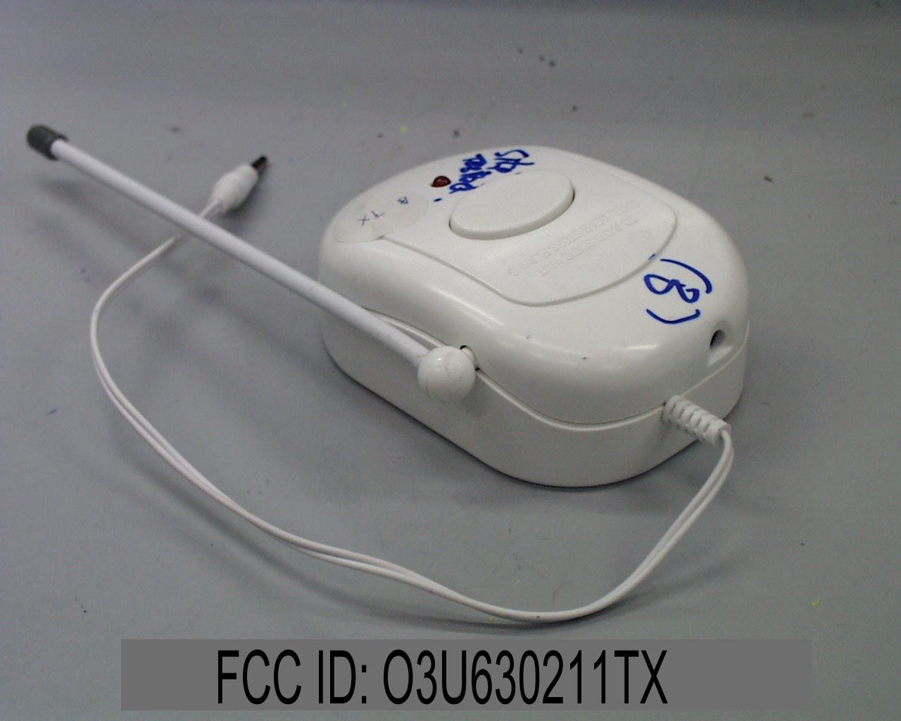
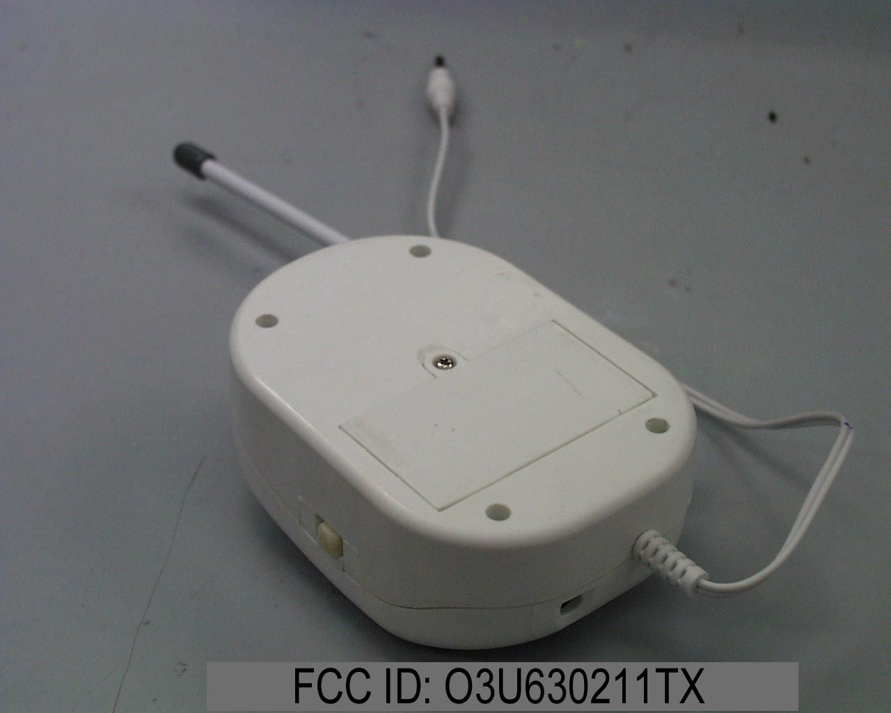
- Wireless Audio Player
- Frequency Range
- 49.84500000 - 49.86600000
- Country
- Hong Kong
Documents & Files
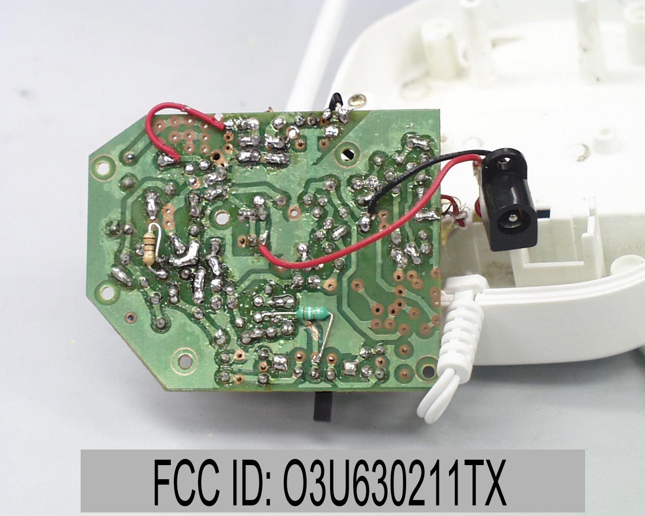
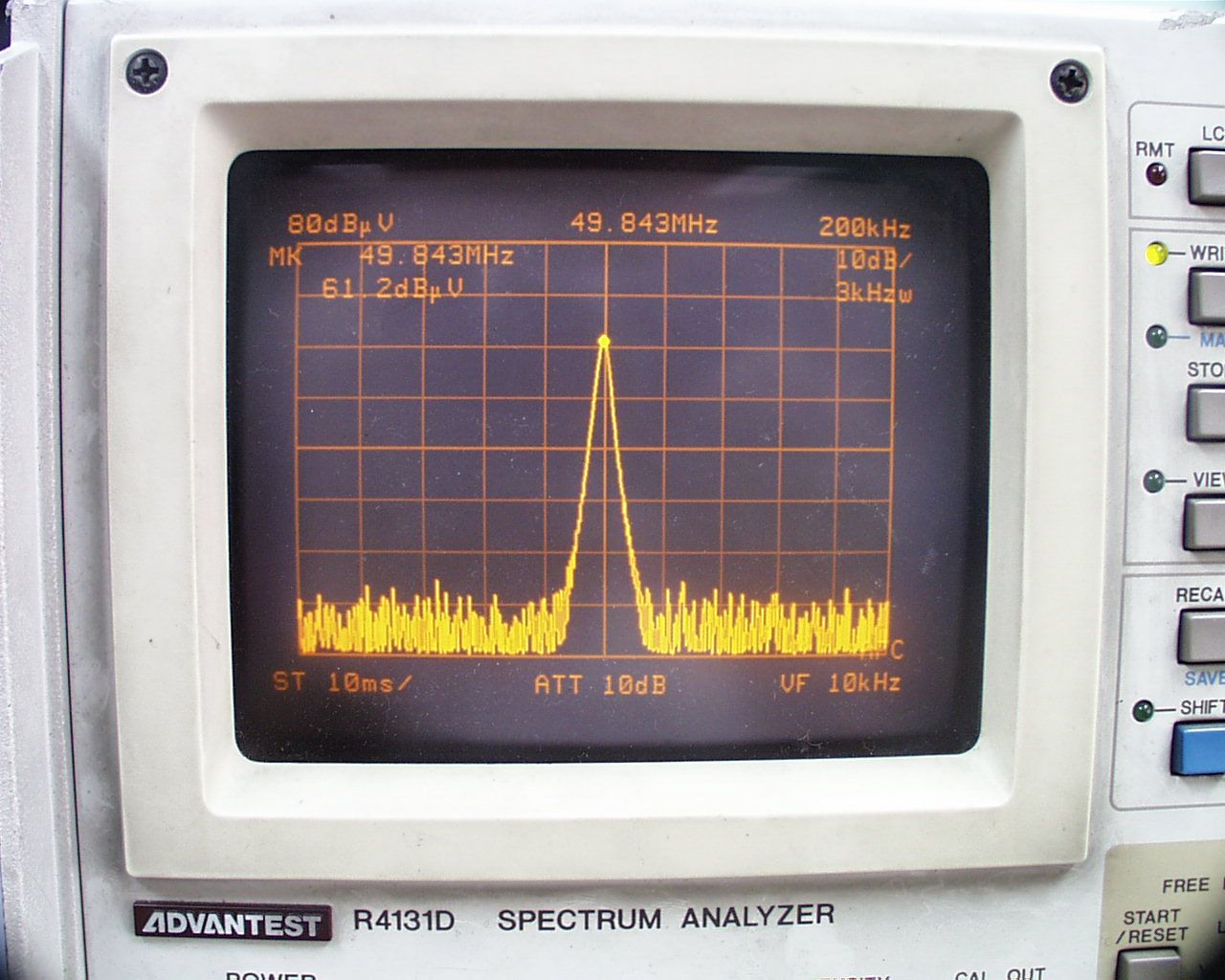
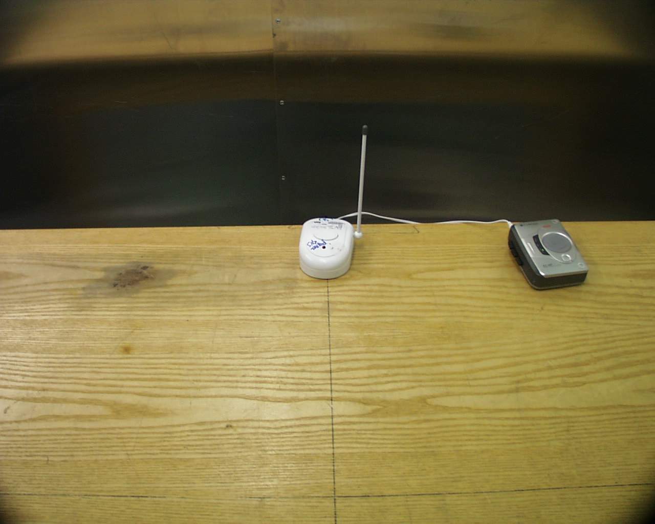
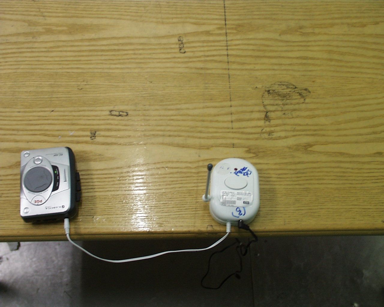
Document Text
Text extracted from the exhibit documents filed with the FCC. Open a document above to read the original.
Users Manual
User Manual for Lulla Bear Features 1.Consists of 2 units, the transmitter unit and receiver unit. 2.Transmitter unit accept audio music from “walkman” or “discman”, modulate the music to RF signal and transmit out to the antenna. 3.Receiver unit receive the RF signal from the antenna, recover the audio music by demodulation and output the music to the speaker. 4.Dual channel selection in both unit. 5.The transmitter unit can be used either 1 x 9V battery cell or AC/DC adaptor which coming with the package. 6.The receiver unit use 4 x 1.5V AA battery cells. 7.“HIGH” or “LOW” volume selection in receiver unit. 8.One hour working timer with re-trigger function in receiver unit. 9.With LED indicator on the transmitter unit indicate the power is “ON or “OFF”. 10.With LED indicator on the receiver unit indicate the unit is in working mode or sleep mode. How To Play 1.Install a 9V battery cell or plug the AC/DC adaptor which come with the package to the transmitter unit (if both 9V battery cell and AC/DC adaptor are installed, only the power of the AC/DC adaptor is used, the path of the battery cell will automatically cut off). 2.Install 4 pcs AA battery cells to the receiver unit. 3.Plug the ear phone jack to a “walkman” or “discman”. 4.Push the power button to power on the transmitter unit, the LED indicator will turn on. 5.Select a channel (CH-A or CH-B) on the transmitter unit for transmission. 6.Slide the channel switch on the receiver unit to select the channel which same as the transmitter unit. 7.Slide the “OFF LO HI” switch of the receiver unit to “LO” or “HI” position (“LO” is low volume, “HI” is high volume) to turn on the unit, the unit will automatically go to working mode, the LED indicator will turn on, the audio music will be hear from the speaker. 8.The receiver unit will continue to work for one hour with +/- 15 minutes tolerance, after that the unit will automatically shut down (go to sleep mode, the music will stop), the LED indicator will turn off. 9.Press the re-trigger button to trigger the receiver unit to working mode again, the unit will then work for one hour and automatically shut down (go to sleep mode). 10.Press the re-trigger button of the receiver unit when the unit is in working mode, the one hour timer will be reset, the one hour timer will be re-start to count again (for example the receiver unit start to work on 9:00, at 9:30 press the re-trigger button, the unit will be automatically go to sleep mode on 10:30). Caution 1.Do not mix old and new batteries. 2.Do not mix alkaline, standard (carbon-zinc), or rechargeable batteries. 3.Only batteries of same or equivalent type as recommend are to be used. 4.Batteries are to be installed with correct polarity. 5.Exhausted batteries are to be removed from the toy. 6.The power supply terminals are not to be short-circuited. Warning : Changes or modifications to this unit not expressly approved by the party responsible for compliance could void the user’s authority to operate the equipment. NOTE : This equipment has been tested and found to comply with the limits for a Class B digital device, pursuant to Part 15 of the FCC Rules. These limits are designed to provide reasonable protection against harmful interference in a residential installation. This equipment generates, uses and can radiate radio frequency energy and, if not installed and used in accordance with the instructions, may cause harmful interference to radio communications. However, there is no guarantee that interference will no occur in a particular installation. If this equipment does cause harmful interference to radio or television reception, which can be determined by turning the equipment off and on, the user is encouraged to try to correct the interference by one or more of the following measures : -Reorient or relocate the receiving antenna. -Increase the separation between the equipment and receiver. -Correct the equipment into an outlet on a circuit different from that to which the receiver is needed. -Consult the dealer or an experienced radio/TV technician for help.
Cover Letter(s)
Frequency Alignment Procedure of #630211 Lulla Bear 1. Transmitter a) Connect the transmitter unit to the DC power supply (+9VDC); b) Use the Spectrum Analyzer to monitor the frequency; c) Slide the channel selector to CH-A position, adjust the coil T2 on the PCB until the frequency reading on the Spectrum Analyzer is 49.845MHz +/-0.005MHz; d) Slide the channel selector to CH-B position, adjust the coil T3 on the PCB until the frequency reading on the Spectrum Analyzer is 49.865MHz +/-0.005MHz; e) Use the wax to seal and fix the coil T2 & T3. 2. Receiver a) Connect the receiver unit to the DC power supply (+6.0VDC); b) Connect a frequency counter across R2 to monitor the frequency; c) Slide the channel selector to CH-B position, the frequency reading on the frequency counter will be 49.79MHz +/-0.005MHz [49.865MHz – 0.075MHz (local oscillator) = 49.79MHz]; d) Slide the channel selector to CH-A position, adjust the coil L9 on the PCB until the frequency reading on the frequency counter is 49.77MHz +/-0.005MHz [49.845MHz – 0.075MHz (local oscillator) = 49.77MHz]; e) Use the wax to seal and fix the coil L9.
Operational Description
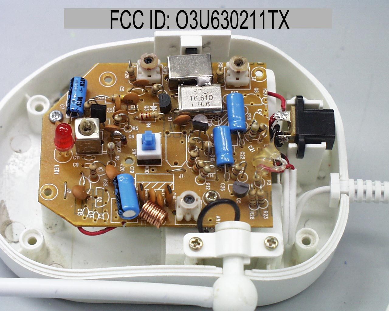
#630211 Lulla Bear Technical Description The product consists of 2 parts, the transmitter unit and receiver unit. The transmitter unit is connected to the music player (“walkman” or “discman”) to accept audio music, and send the music to the receiver unit via the RF channel. The receiver unit demodulate the RF signal from the transmitter unit, and output to the speaker. The transmitter unit is either operated with 1 x 9V battery cells or AC/DC adaptor. When the transmitter unit is powered on and connected to the music player (“walkman” or “discman”), The transmitter unit will modulate the audio music with the carrier signal. The carrier signal is selected by the channel selector (CH-A is 49.845MHz, CH-B is 49.865MHz), the mixed signal (carrier signal and audio music) is sent out via the antenna. The signal is emitted continuously while the transmitter unit is powered on. The receiver unit is either operated with 4 x 1.5V AA battery cells. When the power switch is turned on, the unit is ready to receive the RF signal. If the transmitter unit is powered on and connected to the music player, there will be a RF signal output from the antenna of the transmitter unit. The receiver unit will receive the RF signal, and recover the original music by means of demodulation. At last the audio music is output to the speaker. There is a timer IC inside the receiver unit, which control the working period (one hour timer) of the receiver unit. The receiver unit will automatically go to working mode for 1 hour when the unit is powered on, after that, the unit will go to sleep mode. The receiver unit will resume to work when the re-trigger button is pressed.
Test Report
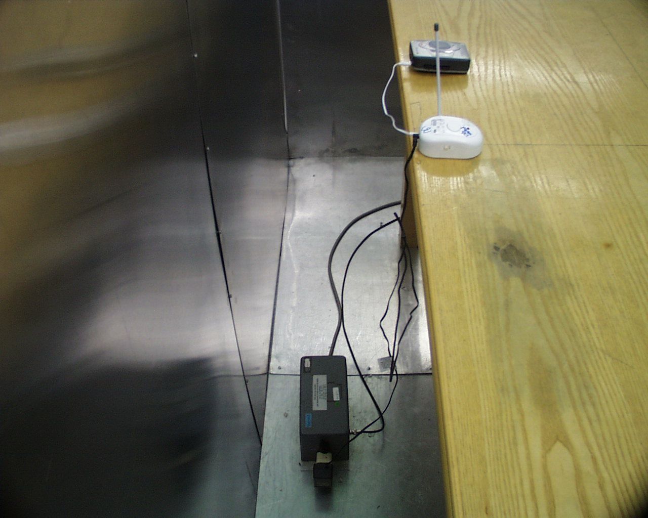
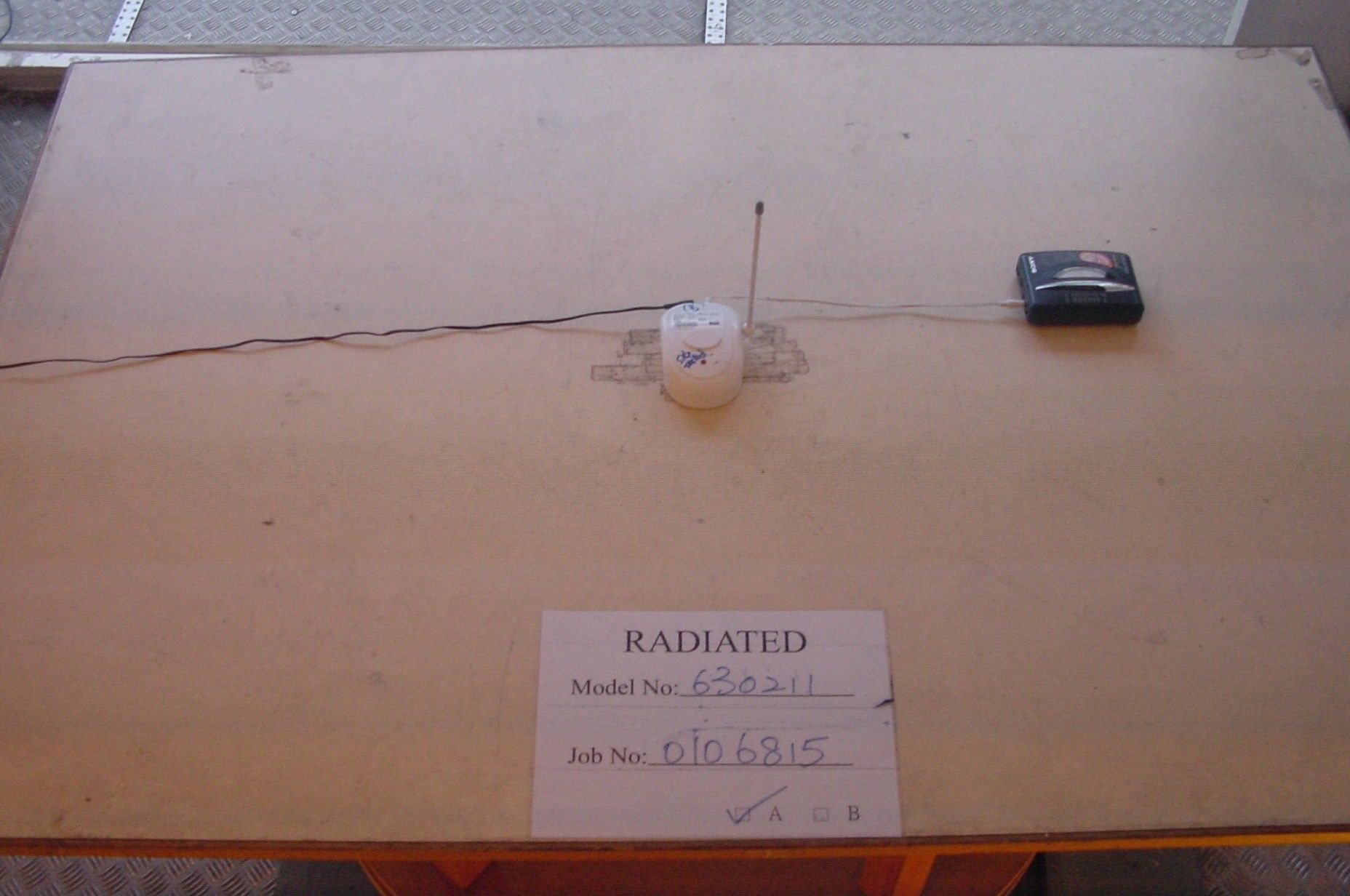
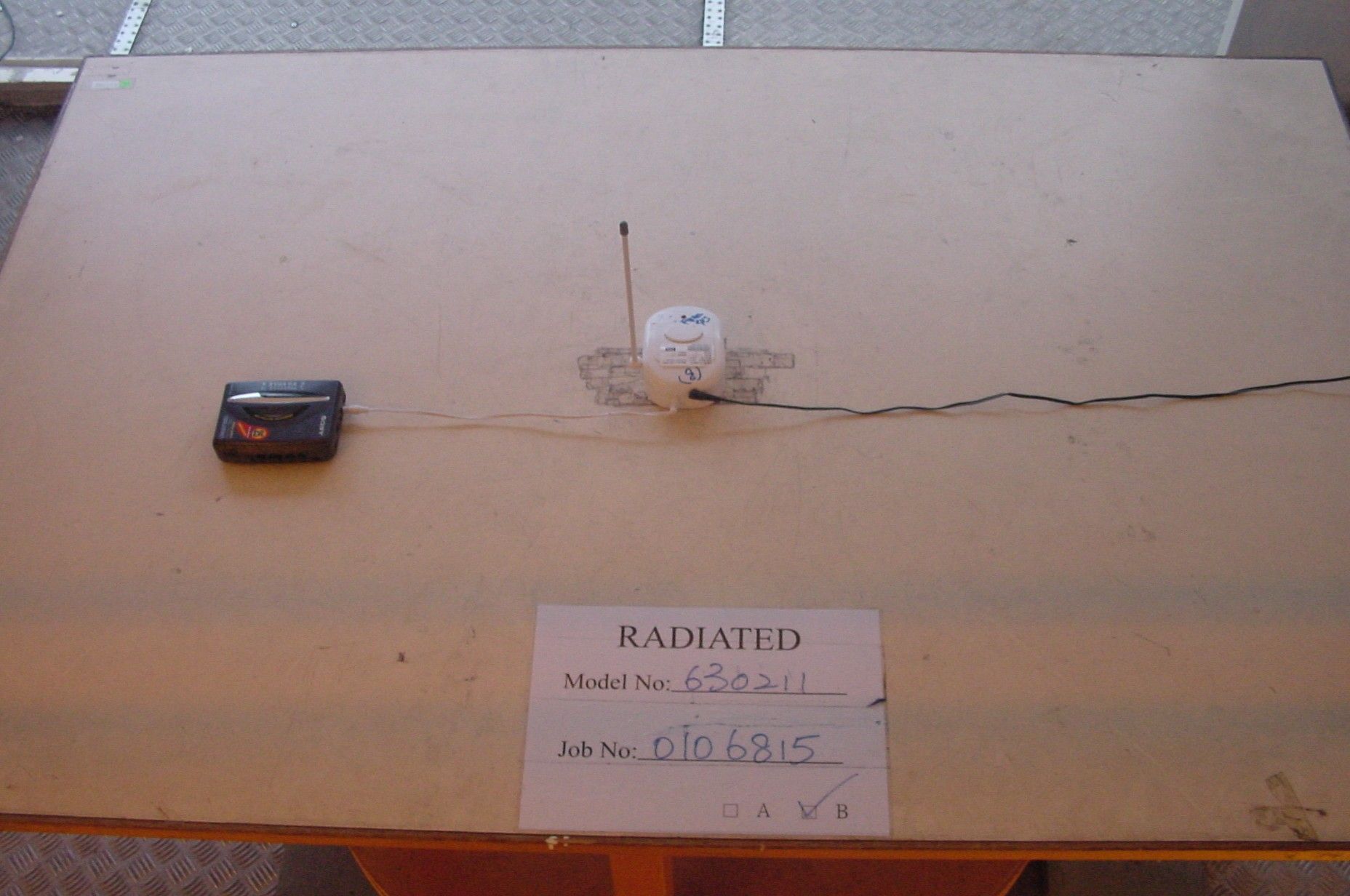
• The test results reported in this report shall refer only to the sample actually tested and shall not refer or be deemed to refer to bulk from which such a sample may be said to have been obtained. • This report shall not be reproduced except in full without prior authorization from Intertek Testing Services Hong Kong Limited FCC ID : O3U630211TX Playmates Asia Services Limited Application For Certification (FCC ID: O3U630211TX) Transmitter, Model : 630211 We hereby certify that the sample of the above item is considered to comply with the requirements of FCC Part 15, Subpart C for Intentional Radiator, mention 47 CFR [10-1-99 edition] WO# 0106815 WN/at June 14, 2001 INTERTEK TESTING SERVICES FCC ID: O3U630211TX i LIST OF EXHIBITS INTRODUCTION EXHIBIT 1:General Description EXHIBIT 2:System Test Configuration EXHIBIT 3:Emission Results EXHIBIT 4:Equipment Photographs EXHIBIT 5:Product Labelling EXHIBIT 6:Technical Specifications EXHIBIT 7:Instruction Manual EXHIBIT 8:Miscellaneous Information INTERTEK TESTING SERVICES FCC ID: O3U630211TX ii MEASUREMENT/TECHNICAL REPORT Playmates Asia Services Limited - MODEL: 630211 FCC ID: O3U630211TX June 14, 2001 This report concerns (check one:)Original Grant X Class II Change Equipment Type: Low Power Transmitter (example: computer, printer, modem, etc.) Deferred grant requested per 47 CFR 0.457(d)(1)(ii)?Yes No X If yes, defer until: date Company Name agrees to notify the Commission by: date of the intended date of announcement of the product so that the grant can be issued on that date. Transition Rules Request per 15.37?Yes No X If no, assumed Part 15, Subpart C for intentional radiator - the new 47 CFR [10-1-96 Edition] provision. Report prepared by:Wilbur Ng Intertek Testing Services 2/F., Garment Center, 576, Castle Peak Road, HONG KONG Phone:852-2173-8502 Fax:852-2742-9149 INTERTEK TESTING SERVICES FCC ID: O3U630211TX iii Table of Contents 1.0 General Description.......................................................................................................................2 1.1 Product Description...................................................................................................................2 1.2 Related Submittal(s) Grants.....................................................................................................2 1.3 Test Methodology......................................................................................................................3 1.4 Test Facility...............................................................................................................................3 2.0 System Test Configuration............................................................................................................5 2.1 Justification...............................................................................................................................5 2.2 EUT Exercising Software..........................................................................................................5 2.3 Special Accessories....................................................................................................................5 2.4 Equipment Modification...........................................................................................................6 2.5 Support Equipment List and Description.................................................................................6 3.0 Emission Results............................................................................................................................8 3.1 Field Strength Calculation........................................................................................................9 3.1 Field Strength Calculation (cont’d).........................................................................................10 3.2 Radiated Emission Configuration Photograph......................................................................11 3.3 Radiated Emission Data.........................................................................................................12 3.4 Line Conducted Configuration Photograph............................................................................14 3.5 Line Conducted Emission Data..............................................................................................15 4.0 Equipment Photographs.............................................................................................................18 5.0 Product Labelling.........................................................................................................................20 6.0 Technical Specifications..............................................................................................................22 7.0 Instruction Manual......................................................................................................................24 8.0 Miscellaneous Information.........................................................................................................26 8.1 Measured Bandwidth..............................................................................................................27 8.2 Emissions Test Procedures.....................................................................................................28 8.2 Emissions Test Procedures (cont'd)........................................................................................29 INTERTEK TESTING SERVICES FCC ID: O3U630211TX iv List of attached file Exhibit typeFile Descriptionfilename Test ReportTest Reportreport.doc Operation DescriptionTechnical Descriptiondescri.pdf Test Setup PhotoRadiated Emissionradiated1.jpg to radiated2.jpg Test Setup PhotoConducted Emissionconduct1.jpg to conduct3.jpg Test ReportConducted Emission Test Resultconduct.pdf Test ReportBandwidth Plotbw1.pdf to bw2.pdf External PhotoExternal Photoophoto1.jpg to ophoto2.jpg Internal PhotoInternal Photoiphoto1.jpg to iphoto2.jpg Block Diagr…
Text truncated - open the document above for the full version.
Contact Information
Applicant
Daniel Cheng
Technical Contact
Intertek Testing Services Hong Kong Ltd.Wilbur Ng
[email protected]852 2173 8502
2/F, Garment Centre · Kowloon · Hong Kong
Non-Technical Contact
Intertek Testing Services Hong Kong Ltd.Wilbur Ng
[email protected]852 2173 8502
Test Firm
Intertek Testing Services Hong KongBilly Chow
Technical Specifications
| # | Rule Parts | Frequency Range | Power Output |
|---|---|---|---|
| 1 | 15C | 49.845 MHz - 49.866 MHz | - |
Other Applications from Playmates Asia Services Limited

O3U-98163
Sep 30, 2006Inductive Toy Doll (RFID Tag Reader)
Equipment Class
DXX - Part 15 Low Power Communication Device Transmitter
O3U-98161R
Apr 08, 2006Inductive Toys
Equipment Class
DXX - Part 15 Low Power Communication Device Transmitter
O3U-98161
Jul 07, 2005Inductive Toys
Equipment Class
DXX - Part 15 Low Power Communication Device Transmitter
O3U-54577
May 29, 2005RC Car
Equipment Class
DXX - Part 15 Low Power Communication Device Transmitter
O3U-54068
May 03, 2004Walkie Talkie
Equipment Class
DXT - Part 15 Low Power Transceiver, Rx Verified