O3YCU458-2Control Unit CU458-2
DewertOkin GmbH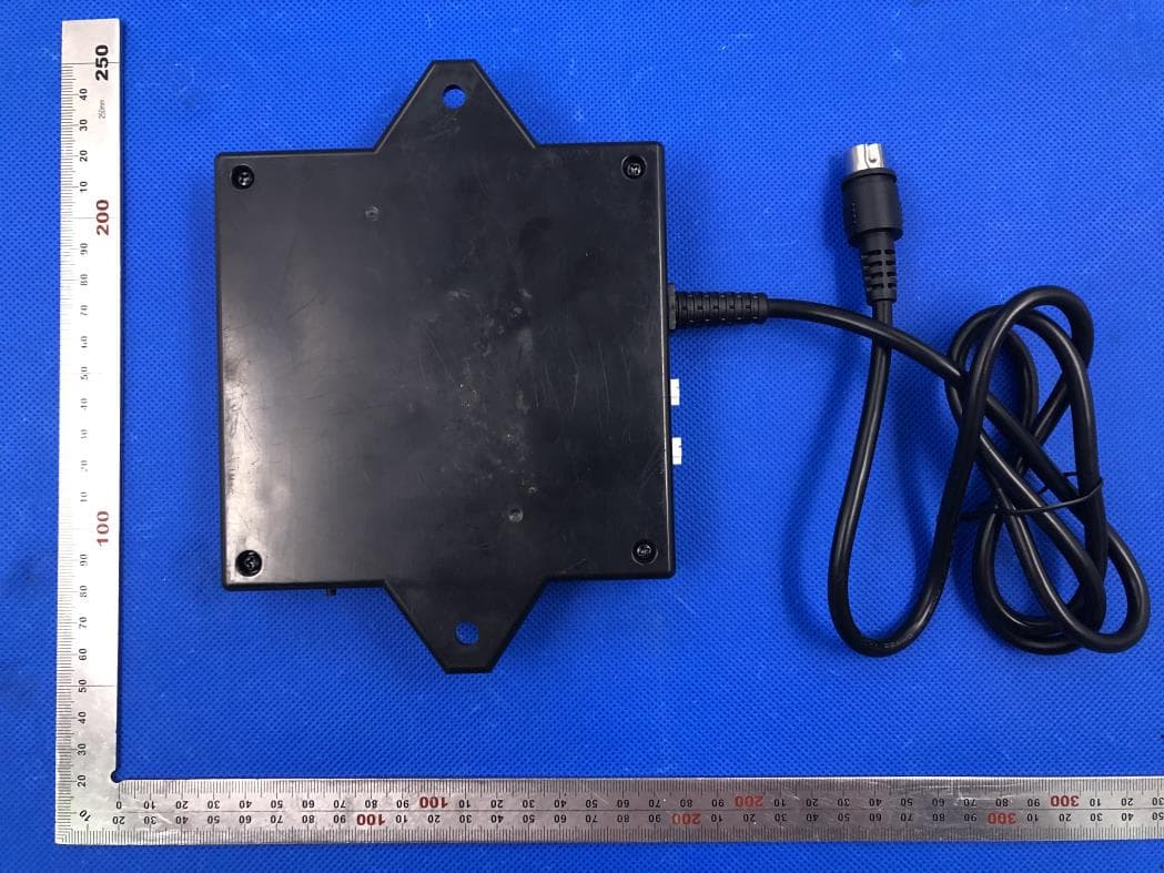
Click to zoom
Application Details
- Equipment Class
- DTS - Digital Transmission System
- Date of Grant
- Apr 14, 2020
- Application Purpose
- Original Equipment
- Date of Application
- Apr 14, 2020
- Equipment Note
- Control Unit CU458-2
- Frequency Range
- 2402.00000000 - 2480.00000000
- Company
- DewertOkin GmbH
- Country
- Germany
Documents & Files
Document Text
Text extracted from the exhibit documents filed with the FCC. Open a document above to read the original.
Users Manual
CONTROL UNIT CU458-2 Installation Instructions (Translation of the original installation instructions) CU458-2 Foreword 93728 1.0 3 Foreword Document revision history Version Date Modification, change 1.0 03/2020 First release Disclaimer and exclusion of liability DewertOkin is not responsible for damage resulting from: • failure to observe these instructions, • changes made to this product which have not been approved by DewertOkin, or • the use of replacement parts which have not been approved or manufactured by DewertOkin. We reserve the right to make unannounced technical changes in the course of our continual product improvement process! Creation of a complete operating instruction manual for the entire end product These instructions are only intended to be used by the end-product manufacturer. They should not be given to the operator of the end product. The factual information contained within may be used as a basis when creating the end-product manual. The warning and danger notices are best suited for use in the end product's manual. However, it is not sufficient to simply follow these notices. You should also carry out an internal risk assessment for your end product. This can then be used as the basis for the safety notices in your manual. These installation instructions do not contain all information required to safely operate the end product. They only describe the installation and operation of the product as partially completed ma- chinery. The instructions are intended for the technicians responsible for manufacturing an end product and not for the operators of the end product. Table of Contents CU458-2 4 93728 1.0 Table of Contents Foreword 3 Document revision history 3 Disclaimer and exclusion of liability 3 Creation of a complete operating instruction manual for the entire end product 3 Table of Contents 4 1. General Information 5 1.1 Configurations 5 1.2 About these installation instructions 5 1.3 Conventions used 5 2. Safety notices 6 2.1 Proper and intended usage 6 2.2 Selection and qualification of personnel 7 2.3 Ratings plate 8 3. Possible combinations 9 4. Description 10 4.1 Components 10 5. Technical specifications 11 6. Installation 13 6.1 Safety notices to observe during installation 13 6.2 Installation procedure 13 7. Information about creating your Operating Manual 16 7.1 General information 16 7.2 Configuring the hand-held remote and app 17 8. Troubleshooting 19 9. Maintenance 20 9.1 Cleaning and care 20 10. Disposal 21 10.1 Packaging material 21 10.2 Components in the control unit 21 Additional information 22 CU458-2 General Information 93728 1.0 5 1.General Information 1.1 Configurations The designation CONTROL UNIT is used in these installation instructions to refer to the CONTROL UNIT CU458-2. 1.2 About these installation instructions In order to install the CONTROL UNIT successfully and safely in the end product, these installation instructions must be observed. These instructions are not an operating manual for the end product. These instructions will help you to minimize danger, repair costs and down times. They will also help you to increase the reliability and lifespan of the device. CAUTION The notices in these instructions must be followed! Following the guidelines during installation and connection procedures will help to minimize: •the risk of accident and injury, and •damage to the CONTROL UNIT or the end product. T hese installation instructions have been written with due care and attention. However, we cannot guarantee that the data, images and drawings are complete and correct nor do we accept any lia- bility for the information contained therein, unless required by law. 1.3 Conventions used Notices which do not relate to safety are indicated in these instructions with a symbol: Triangular notice symbol Explanations of warning notices CAUTION CAUTION indicates a hazardous situation which, if not avoided, could result in minor or moder- ate injury. N OTICE NOTICE is used to address practices which are not related to personal injury but may result in damage to the product or surroundings. Safety notices CU458-2 6 93728 1.0 2.Safety notices 2.1 Proper and intended usage The CONTROL UNIT is intended for use: •as a control unit for suitable DewertOkin drive systems, •for HOME applications (in beds, reclining chairs, etc.). CAUTION Risk of accident This CONTROL UNIT should only be used for the applications described above. Any other use is forbidden. Improper usage can lead to accidents or destruction of the unit. Such non-approved applications will lead immediately to the expiration of all guarantee and warranty claims on the part of the end-product manufacturer against the manufacturer. 2 .1.1 Improper usage Be sure to follow the notices below concerning improper usage. You should include them in your product manual in order to inform the users of your end product. The CONTROL UNIT should not be used: •in any environment where combustible or explosive gases or vapours (e.g., anaesthesiology) may be present, •in the proximity of open fires or other heat sources (such as furnaces, ovens or direct sunlight), •as a power source for toys or games, •in any application that will be cleaned with an automated washing system, •in a moist environment, or •outdoors. The CONTROL UNIT can be used by children of 8 years and older, persons with reduced physical, sensory or mental capabilities, or persons with lack of experience or knowledge when they are su- pervised or instructed concerning the safe use of the device and when they understand the result- ing risks. Do not allow children to play with this device. The cleaning and user maintenance must not be carried out by children without supervision. You should only use spare parts which have been manufactured or approved by DewertOkin. Only these parts will guarantee a sufficient level of safety. CU458-2 Safety notices 93728 1.0 7 2.2 Selection and qualification of personnel The installation of the CONTRO…
Text truncated - open the document above for the full version.
Cover Letter(s)
DewertOkin GmbH Weststr. 1, 32278 , Kirchlengern, Germany [Mar. 25, 2020] Federal Communications Commission 445 12 th Street SW Washington, DC 20554 Subject: Limited Agency Agreement DewertOkin GmbH FCC ID: O3YCU458-2 To Whom It May Concern: We, DewertOkin GmbH hereby authorized Intertek Testing Services to act as our Agent for the purpose of preparing application for FCC ID number (O3YCU458-2) under all applicable parts of the FCC rules and regulations. The effective date of this limited agency agreement is (2020-03-25). The Limited Agency Agreement expires until further notice, unless sooner terminated or extended by written notice to Intertek Testing Services and the Federal Communications Commission. This is to advise that we are in full compliance with the Anti-Drug Abuse Act. The applicant is not subject to a denial of federal benefits pursuant to Section 5301 of the Anti-Drug Act of 1988, 21 U.S.C. 862, and no party to the application is subject to a denial of federal benefits pursuant to that section. If you have any questions or comments, please do not hesitate to contact me. Sincerely, [Signature] DewertOkin GmbH Contact person: Werner Kracht Title: Engineer
Cover Letter(s)
DewertOkin GmbH Weststr. 1, 32278 , Kirchlengern, Germany Mar. 25, 2020 Federal Communication Commission Authorization and Evaluation Division FCC ID: O3YCU458-2 Re: Confidentiality Request Pursuant to Sections 0.457 and 0.459 of the Commission’s Rules, the applicant hereby requests confidential treatment of information applied this application as outlined below: 1: Block Diagram 2: Schematics 3: Operational Description The above materials contain trade secrets and proprietary information not customarily released to the public. The public disclosure of these matters might be harmful to the applicant and provide unjustified benefits to its competitors. The Applicant understands that pursuant to Rules 0.457, disclosure of this Application and all accompanying documentation will not be made before the date of the Grant for this application. Sincerely, DewertOkin GmbH Contact person: Werner Kracht Title: Engineer
External Photos
External Photos TOP VIEW OF EUT BOTTOM VIEW OF EUT FRONT VIEW OF EUT BACK VIEW OF EUT LEFT VIEW OF EUT RIGHT VIEW OF EUT VIEW OF EUT(PORT)-1 VIEW OF EUT(PORT)-2
ID Label/Location Info
FCC ID and IC Label Location 35mm*25mm
Internal Photos
Internal Photos OPEN VIEW OF EUT INTERNAL VIEW OF EUT-1 INTERNAL VIEW OF EUT-2 INTERNAL VIEW OF EUT-3 Antenna INTERNAL VIEW OF EUT-4 INTERNAL VIEW OF EUT-5 ADAPTER
RF Exposure Info
RF EXPOSURE EVALUATION 1. PRODUCT INFORMATION Product Description Control Unit CU458-2 Model Name A1320 FCC ID O3YCU458-2 2. EVALUATION METHOD According to 447498 D01 General RF Exposure Guidance v05 The 1-g and 10-g SAR test exclusion thresholds for 100 MHz to 6 GHz at test separation distances ≤ 50 mm are determined by: [(max. power of channel, including tune-up tolerance, mW)/(min. test separation distance, mm)] ·[√f(GHz)] ≤ 3.0 for 1-g SAR and ≤ 7.5 for 10-g extremity SAR. Where f(GHz) is the RF channel transmit frequency in GHz Power and distance are rounded to the nearest mW and mm before calculation 3. CALCULATION BLE: P t =-3.690dBm=0.43mW The value of the Maximum output power P t is referred to the test report of the CFR47 §15.247. The result for RF exposure evaluation SAR=(0.43mW /5mm) .[√2.48(GHz)]= 0.14<3.0 for 1-g SAR and ≤ 7.5 for 10-g extremity SAR. 2.4G GFSK: P t =-0.649dBm=0.86mW The value of the Maximum output power P t is referred to the test report of the CFR47 §15.247. The result for RF exposure evaluation SAR=(0.86mW /5mm) .[√2.403(GHz)]= 0.27<3.0 for 1-g SAR and ≤ 7.5 for 10-g extremity SAR. Note: BLE and 2.4G GFSK don't work at the same time. 4. CONCLUSION The SAR evaluation is not required.
Test Report
Page 1 of 49 FCC Test Report Report No.: AGC06638200201FE02 FCC ID : O3YCU458-2 APPLICATION PURPOSE : Original Equipment PRODUCT DESIGNATION : Control Unit CU458-2 BRAND NAME : OKIN MODEL NAME : A1320 APPLICANT : DewertOkin GmbH DATE OF ISSUE : Mar. 25, 2020 STANDARD(S) : FCC Part 15.247 REPORT VERSION : V1.0 Attestation of Global Compliance (Shenzhen) Co., Ltd CAUTION: This report shall not be reproduced except in full without the written permission of the test laboratory and shall not be quoted out of context. Report No.: AGC06638200201FE02 Page 2 of 49 REPORT REVISE RECORD Report Version Revise Time Issued Date Valid Version Notes V1.0 / Mar. 25, 2020 Valid Initial Release Report No.: AGC06638200201FE02 Page 3 of 49 TABLE OF CONTENTS 1. VERIFICATION OF COMPLIANCE ..............................................................................................................5 2.GENERAL INFORMATION ...........................................................................................................................6 2.1PRODUCT DESCRIPTION ......................................................................................................................6 2.2. TABLE OF CARRIER FREQUENCYS ....................................................................................................6 2.3 RELATED SUBMITTAL(S)/GRANT(S) ....................................................................................................7 2.4TEST METHODOLOGY ...........................................................................................................................7 2.5 SPECIAL ACCESSORIES ......................................................................................................................7 2.6 EQUIPMENT MODIFICATIONS ..............................................................................................................7 3. MEASUREMENT UNCERTAINTY ...............................................................................................................8 4. DESCRIPTION OF TEST MODES ...............................................................................................................9 5. SYSTEM TEST CONFIGURATION ............................................................................................................ 10 5.1 CONFIGURATION OF TESTED SYSTEM ............................................................................................ 10 5.2 EQUIPMENT USED IN TESTED SYSTEM ............................................................................................ 10 5.3. SUMMARY OF TEST RESULTS .......................................................................................................... 10 6. TEST FACILITY ......................................................................................................................................... 11 7. PEAK OUTPUT POWER ........................................................................................................................... 12 7.1. MEASUREMENT PROCEDURE .......................................................................................................... 12 7.2. TEST SET-UP (BLOCK DIAGRAM OF CONFIGURATION) .................................................................. 12 7.3. LIMITS AND MEASUREMENT RESULT .............................................................................................. 13 8. 6 DB BANDWIDTH .................................................................................................................................... 15 8.1. MEASUREMENT PROCEDURE .......................................................................................................... 15 8.2. TEST SET-UP (BLOCK DIAGRAM OF CONFIGURATION) .................................................................. 15 8.3. LIMITS AND MEASUREMENT RESULTS ............................................................................................ 15 9. CONDUCTED SPURIOUS EMISSION ....................................................................................................... 17 9.1. MEASUREMENT PROCEDURE .......................................................................................................... 17 9.2. TEST SET-UP (BLOCK DIAGRAM OF CONFIGURATION) .................................................................. 17 9.3. MEASUREMENT EQUIPMENT USED ................................................................................................. 17 9.4. LIMITS AND MEASUREMENT RESULT .............................................................................................. 17 10. MAXIMUM CONDUCTED OUTPUT POWER SPECTRAL DENSITY ....................................................... 22 Report No.: AGC06638200201FE02 Page 4 of 49 10.1 MEASUREMENT PROCEDURE ......................................................................................................... 22 10.2 TEST SET-UP (BLOCK DIAGRAM OF CONFIGURATION) ................................................................. 22 10.3 MEASUREMENT EQUIPMENT USED ................................................................................................ 22 10.4 LIMITS AND MEASUREMENT RESULT ............................................................................................. 22 11. RADIATED EMISSION ............................................................................................................................. 24 11.1. MEASUREMENT PROCEDURE ........................................................................................................ 24 11.2. TEST SETUP ..................................................................................................................................... 25 11.3. LIMITS AND MEASUREMENT RESULT ............................................................................................ 26 11.4. TEST RESULT ...................................................................................................................................…
Text truncated - open the document above for the full version.
Test Report
Page 1 of 49 FCC Test Report Report No.: AGC06638200201FE01 FCC ID : O3YCU458-2 APPLICATION PURPOSE : Original Equipment PRODUCT DESIGNATION : Control Unit CU458-2 BRAND NAME : OKIN MODEL NAME : A1320 CLIENT : DewertOkin GmbH DATE OF ISSUE : Mar. 25, 2020 STANDARD(S) : FCC Part 15.247 REPORT VERSION : V1.0 Attestation of Global Compliance (Shenzhen) Co., Ltd CAUTION: This report shall not be reproduced except in full without the written permission of the test laboratory and shall not be quoted out of context. Report No.: AGC06638200201FE01 Page 2 of 49 REPORT REVISE RECORD Report Version Revise Time Issued Date Valid Version Notes V1.0 / Mar. 25, 2020 Valid Initial Release Report No.: AGC06638200201FE01 Page 3 of 49 TABLE OF CONTENTS 1. VERIFICATION OF COMPLIANCE ..............................................................................................................5 2.GENERAL INFORMATION ...........................................................................................................................6 2.1PRODUCT DESCRIPTION ......................................................................................................................6 2.2. TABLE OF CARRIER FREQUENCYS ....................................................................................................6 2.3 RELATED SUBMITTAL(S)/GRANT(S) ....................................................................................................7 2.4TEST METHODOLOGY ...........................................................................................................................7 2.5 SPECIAL ACCESSORIES ......................................................................................................................7 2.6 EQUIPMENT MODIFICATIONS ..............................................................................................................7 3. MEASUREMENT UNCERTAINTY ...............................................................................................................8 4. DESCRIPTION OF TEST MODES ...............................................................................................................9 5. SYSTEM TEST CONFIGURATION ............................................................................................................ 10 5.1 CONFIGURATION OF TESTED SYSTEM ............................................................................................ 10 5.2 EQUIPMENT USED IN TESTED SYSTEM ............................................................................................ 10 5.3. SUMMARY OF TEST RESULTS .......................................................................................................... 10 6. TEST FACILITY ......................................................................................................................................... 11 7. PEAK OUTPUT POWER ........................................................................................................................... 12 7.1. MEASUREMENT PROCEDURE .......................................................................................................... 12 7.2. TEST SET-UP (BLOCK DIAGRAM OF CONFIGURATION) .................................................................. 12 7.3. LIMITS AND MEASUREMENT RESULT .............................................................................................. 13 8. 6 DB BANDWIDTH .................................................................................................................................... 15 8.1. MEASUREMENT PROCEDURE .......................................................................................................... 15 8.2. TEST SET-UP (BLOCK DIAGRAM OF CONFIGURATION) .................................................................. 15 8.3. LIMITS AND MEASUREMENT RESULTS ............................................................................................ 15 9. CONDUCTED SPURIOUS EMISSION ....................................................................................................... 17 9.1. MEASUREMENT PROCEDURE .......................................................................................................... 17 9.2. TEST SET-UP (BLOCK DIAGRAM OF CONFIGURATION) .................................................................. 17 9.3. MEASUREMENT EQUIPMENT USED ................................................................................................. 17 9.4. LIMITS AND MEASUREMENT RESULT .............................................................................................. 17 10. MAXIMUM CONDUCTED OUTPUT POWER SPECTRAL DENSITY ....................................................... 22 Report No.: AGC06638200201FE01 Page 4 of 49 10.1 MEASUREMENT PROCEDURE ......................................................................................................... 22 10.2 TEST SET-UP (BLOCK DIAGRAM OF CONFIGURATION) ................................................................. 22 10.3 MEASUREMENT EQUIPMENT USED ................................................................................................ 22 10.4 LIMITS AND MEASUREMENT RESULT ............................................................................................. 22 11. RADIATED EMISSION ............................................................................................................................. 24 11.1. MEASUREMENT PROCEDURE ........................................................................................................ 24 11.2. TEST SETUP ..................................................................................................................................... 25 11.3. LIMITS AND MEASUREMENT RESULT ............................................................................................ 26 11.4. TEST RESULT ................................................................................................................................... 26…
Text truncated - open the document above for the full version.
Test Setup Photos
Test Setup Photos RADIATED EMISSION TEST SETUP BELOW 1GHZ RADIATED EMISSION TEST SETUP ABOVE 1GHZ CONDUCTED EMISSION TEST SETUP
Contact Information
Applicant
Werner Kracht(Engineer)
Technical Contact
Attestation of Global Compliance (Shenzhen) Co., LYimi Zhao
[email protected]86-755-29081977
2F.,No.2 Building, Huafeng No.1 Technical Industri · Shenzhen · China
Test Firm
Attestation of Global Compliance (Shenzhen) Co., LDoris Li
[email protected]+86-755-25234088
Technical Specifications
| # | Rule Parts | Frequency Range | Power Output |
|---|---|---|---|
| 2 | 15C | 2.40 GHz - 2.48 GHz | 430.00 µW |
Other Applications from DewertOkin GmbH
O3YENS
Jul 21, 2020RF-ENHANCE-ANGLE
Equipment Class
DXX - Part 15 Low Power Communication Device Transmitter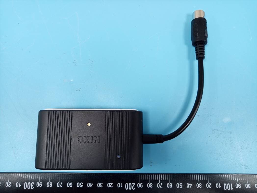
O3YRFECOBTM
Jul 06, 2020RF ECO BT M
Equipment Class
DXX - Part 15 Low Power Communication Device Transmitter
O3YENH
Jun 28, 2020RF-ENHANCE-STRAIGHT
Equipment Class
DXX - Part 15 Low Power Communication Device Transmitter
O3YF105820
Apr 29, 2020RF-1058
Equipment Class
DXX - Part 15 Low Power Communication Device Transmitter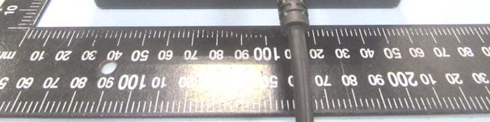
O3YRF202A
Nov 04, 2015HE200
Equipment Class
DXX - Part 15 Low Power Communication Device Transmitter