O3YRFECOBTMRF ECO BT M
DewertOkin GmbH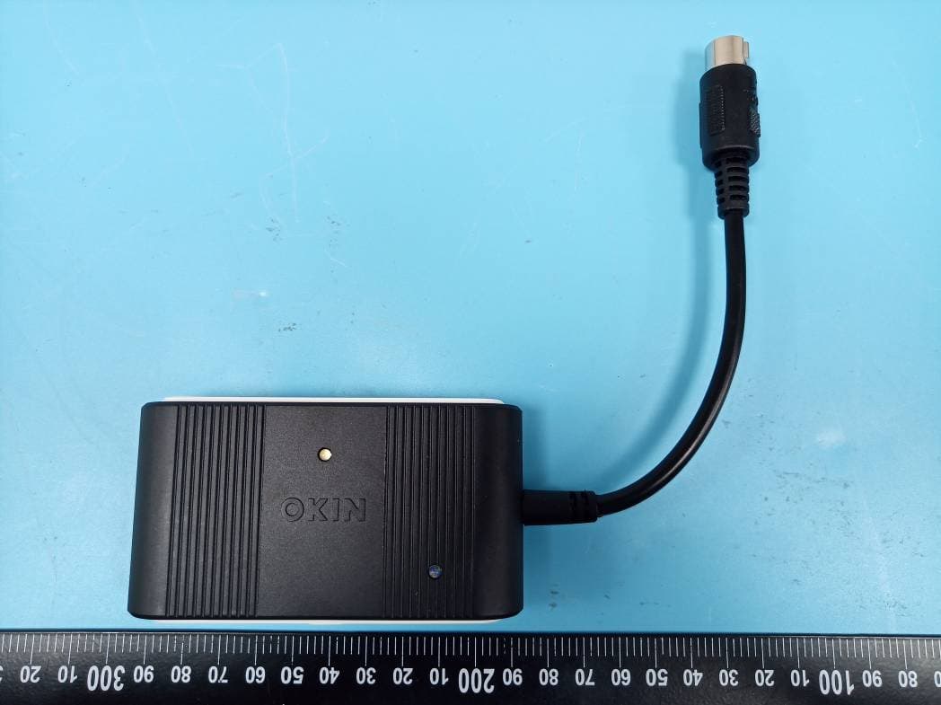
Click to zoom
Application Details
- Equipment Class
- DXX - Part 15 Low Power Communication Device Transmitter
- Date of Grant
- Jul 06, 2020
- Application Purpose
- Original Equipment
- Date of Application
- Jul 06, 2020
- Equipment Note
- RF ECO BT M
- Frequency Range
- 2403.00000000 - 2476.00000000
- Company
- DewertOkin GmbH
- Country
- Germany
Documents & Files
Document Text
Text extracted from the exhibit documents filed with the FCC. Open a document above to read the original.
Users Manual
Quick Guide RF ECO BT M Acknowledgement: The Pairing LED (b) will blink twice sound to signal the successful completion of thestep. Teach-in for the RF remote or app: To start using the RF remote with a Bluetooth ® device, the wireless link with the RF ECO BT M must first be established. In order to use a Bluetooth ® device (a smart phone or tablet) with your system, you will first need to download and install the "OKIN" app for your device. Automatic teach-in Connect the RF ECO BT M to the drive system and put thepower plug into thesocket. The RF ECO BT M will be in pairing mode for 120sec which is divided as follows: During the first 60sec, an RF remote can be discovered (the teach-in). During the next 60sec, a Bluetooth ® device can bediscovered. The Pairing LED (b) and the Bluetooth ® LED (c) are illuminated during this teach-in phase for the RFremote. To pair the RF hand-held remote, please refer to the instructions for the RF hand-held remote. A successful pairing will be acknowledged. The Pairing LED (b) will switch off after the teach-in process for the RF remote is finished. The Bluetooth ® LED (c) for pairing with a Bluetooth ® device startsflashing. The Bluetooth ® LED (c) switches off when the Bluetooth ® pairing process has timed out or when the device has connectedsuccessfully. A successful pairing will be acknowledged. If, during the RF remote's teach-in process, you press any button on an already paired RF remote, then it switches to the Bluetooth ® teach-inmode. If the RF remote or a Bluetooth ® device is discovered during the pairing phase, then this pairing mode is automatically ended. The Pairing LED (b) and the Bluetooth ® LED (c) switchoff. Repeat the automatic teach-in process. First, remove the plug from the power supply. Then wait 60sec and insert the plug back into the power supply. You can now start the new teach-in process. Paralleloperation: Note! Put the drive systems into service one after the other. Do not attempt to put several drive systems into service simultaneously. Otherwise the drives will be unable to assign the RF ECO BT M precisely. Manuel teach-in The system must be connected to the power supply. Connect the RF ECO BT M to the drivesystem. Quickly press the Pairing button (a) twice on the RF ECO BT M. The Pairing LED (b) and the Bluetooth ® LED (c) will illuminate. The RF ECO BT M is now in pairing mode for 120 seconds, which is divided as follows: During the first 60 seconds, an RF remote can be discovered (the teach-in). During the next 60 seconds,a Bluetooth ® device can be discovered. The Pairing LED (b) and the Bluetooth ® LED (c) are illuminated during this teach-in phase for the RFremote. To pair the RF hand-held remote, please refer to the instructions for the RF hand-held remote. A successful pairing will be acknowledged. The Pairing LED (b) will switch off after the teach-in process for the RF remote is finished. The Bluetooth ® LED (c) for pairing with a Bluetooth ® device startsflashing. The Bluetooth ® LED (c) switches off when the Bluetooth ® pairing process has timed out or when the device has connectedsuccessfully. A successful pairing will be acknowledged. If, during the RF remote's teach-in process, you press any button on an already paired RF remote, then it switches to the Bluetooth ® teach-inmode. If the RF remote or a Bluetooth ® device is discovered during the pairing phase, then this pairing mode is automatically ended. The Pairing LED (b) and the Bluetooth ® LED (c) switchoff. Paralleloperation: Note! Put the drive systems into service one after the other. Do not attempt to put several drive systems into service simultaneously. Otherwise the drives will be unable to assign the RF ECO BT M precisely. Referencing the drive system To enable all the functions of the drive system for use, you must perform a reference test. Press and hold the Pairing button (a) on the RF ECO BT M until all drives reach their endposition. Keep the Pairing button (a) pressed for a further 5seconds. Successful pairing will beacknowledged. Electrical reset function (with battery connected to the drive system in a power outage) Press the Pairing button (a) on the RF ECO BT M and keep it pressed until the drive has retractedfully. For the electrical reset function with the RF hand-held remote, please refer to the instructions for the RF hand-heldremote. Attention! After a test with the electrical reset function or when the system was de-energised, a reference test must be performed. Saving the memory positions To save the memory position of the RF hand-held remote, please refer to the instructions for the RF hand-held remote. Attention! Before saving the memory positions, a reference test must be performed. Resetting the factory settings Give the Pairing button (a) 4x short press in succession.The Pairing LED (b) lights on. Now actuate the Pairing button (a) one times. The PairingLED (b) lighting extinguishes. The RF-remote isdeactivated. RF ECO BT M c b a b FCC Warning / IC Warning FCC: This device complies with Part 15 of the FCC Rules. Operation is subject to the following two conditions: (1) this device may not cause harmful interference, and (2) this device must accept any interference received, including interference that may cause undesired operation. Any changes or modifications not approved by the party responsible for compliance could void the user's authority to operate the equipment. Note: This equipment has been tested and found to comply with the limits for a Class B digital device, pursuant to part 15 of the FCC Rules. These limits are designed to provide reasonable protection against harmful interference in a residential installation. This equipment generates, uses and can radiate radio frequency energy and, if not installed and used in accordance with the instructions, may cause harmful interference to radio communications. However, there is no guarantee that interference will not oc…
Text truncated - open the document above for the full version.
Cover Letter(s)
Company Name:.DewertOkin GmbH Add: Weststr.1,32278KirchIengern,Germany Tel: +49 5223 979 184 Email: [email protected] QA-FR-170-B 7/29/2014 FCC Authorization Date: 2020-5-25 FEDERAL COMMUNICATIONS COMMISSIONS Authorization and Evaluation Division 7435 Oakland Mills Road Columbia, MD 21046 Subject: Agent Authorization To whom it may concern: We DewertOkin GmbH, the undersigned, hereby authorizes Bay Area Compliance Laboratories Corporation to act on its behalf in all matters relating to application for Equipment authorization, including the signing of all documents relating to these matters. All acts carried out by Bay Area Compliance Laboratories Corporation on our behalf shall have the same effect as our own action. We, the undersigned, hereby certify that we are not subject to a denial of federal benefits, that includes FCC benefits, pursuant to Section 5301 of the Anti-Drug Abuse Act of 1988, 21 U.S.C. 862. This authorization is valid until further written notice from the applicant. Sincerely Yours, Signature: Werner Kracht Engineer
Cover Letter(s)
Company Name:DewertOkin GmbH Add: Weststr.1,32278 KirchIengern,Germany Tel: +49 5223 979 184 Email:[email protected] FCC Confidential Authorization Date: 2020-5-25 FEDERAL COMMUNICATIONS COMMISSIONS Authorization and Evaluation Division 7435 Oakland Mills Road Columbia, MD 21046 Subject: Confidentiality Request regarding application for certification of FCC ID: O3YRFECOBTM In accordance with Sections 0.457 and 0.459 of the Commission’s Rules, DewertOkin GmbH hereby requests long-term confidential treatment of information accompanying this application as outlined below: Block Diagram--- (Long term) Circuit Description--- (Long term) Detailed Circuit Schematics of EUT--- (Long term) The above materials contain proprietary and confidential information not customarily released to the public. The public disclosure of these materials provides unjustified benefits to its competitors in the market. Sincerely Yours, Signature: Werner Kracht Engineer
Cover Letter(s)
Company Name: DewertOkin GmbH Add: Weststr.1, 32278KirchIengern, Germany Tel: +49 5223 979 184 Email: [email protected] Product Similarity Declaration 2020-03-11 FEDERAL COMMUNICATIONS COMMISSIONS Authorization and Evaluation Division 7435 Oakland Mills Road Columbia, MD 21046 To whom it may concern: We, DewertOkin GmbH hereby declare that we have products named as RF ECO BT M, FCC ID: O3YRFECOBTM, Model: A1308US, adding models: A1308EU was tested by BACL, for marketing purpose, we would like to list all the series models on reports and certificate, all the models are identical in the main board, but are different in below items: The product is provided in different colors depends on customer requirements. The product is provided in different LED Lamp position depends on customer requirements. We confirm that all information above is true, and we’ll be responsible for all the consequences. We confirm those different variants have no effect on Safety, EMC, Radio and Health test. Please contact me if you have any question. Sincerely, Signature, Printed Name: Werner Kracht Title: Engineer
External Photos
EXHIBIT B - EUT EXTERNAL PHOTOGRAPHS For A1308US For A1308EU
ID Label/Location Info
EXHIBIT A - FCC ID LABEL AND LOCATION FCC ID Label FCC ID Label Location Information The label shown shall be permanently affixed at a conspicuous location on the device and be readily visible to the user at the time purchase (Labeling requirements per 2.925)
Internal Photos
EXHIBIT C - EUT INTERNAL PHOTOGRAPHS For A1308US \ BLE&2.4G SRD Antenna For A1308EU BLE&2.4G SRD Antenna
Test Report
Note: This report must not be used by the customer to claim product certification, approval, or endorsement by A2LA* or any agency of the Federal Government. This report may contain data that are not covered by the A2LA accreditation and are marked with an asterisk “★”. BACL is not responsible for the authenticity of any test data provided by the applicant. Data included from the applicant that may affect test results are marked with an asterisk ’*’. Customer model name, addresses, names, trademarks etc. are not considered data. This report cannot be reproduced except in full, without prior written approval of the Company. Unless otherwise stated the results shown in this test report refer only to the sample(s) tested. This report is valid only with a valid digital signature. The digital signature may be available only under the Adobe software above version 7.0. FCC PART 15.249 TEST REPORT For DewertOkin GmbH Weststr. 1, 32278 Kirchlengern, Germany FCC ID: O3YRFECOBTM Report Type: Original Report Product Type: RF ECO BT M Report Number: RSZ200317551-00B Report Date: 2020-04-24 Reviewed By: Jimmy Xiao RF En gineer Prepared By: Bay Area Compliance Laboratories Corp. (Shenzhen) 6/F., West Wing, Third Phase of Wanli Industrial Building, Shihua Road, Futian Free Trade Zone, Shenzhen, Guangdong, China Tel: +86-755-33320018 Fax: +86-755-33320008 www.baclcorp.com.cn Bay Area Compliance Laboratories Corp. (Shenzhen) Report No.: RSZ200317551-00B FCC Part 15.249 Page 2 of 26 TABLE OF CONTENTS GENERAL INFORMATION ....................................................................................................................................... 3 PRODUCT DESCRIPTION FOR EQUIPMENT UNDER TEST (EUT) ..................................................................................... 3 OBJECTIVE ................................................................................................................................................................... 3 RELATED SUBMITTAL(S)/GRANT(S) ............................................................................................................................. 3 TEST METHODOLOGY .................................................................................................................................................. 3 MEASUREMENT UNCERTAINTY .................................................................................................................................... 4 TEST FACILITY ............................................................................................................................................................. 4 SYSTEM TEST CONFIGURATION .......................................................................................................................... 5 JUSTIFICATION ............................................................................................................................................................. 5 EUT EXERCISE SOFTWARE .......................................................................................................................................... 5 EQUIPMENT MODIFICATIONS ....................................................................................................................................... 5 SUPPORT EQUIPMENT LIST AND DETAILS .................................................................................................................... 5 EXTERNAL I/O CABLE .................................................................................................................................................. 5 BLOCK DIAGRAM OF TEST SETUP ................................................................................................................................ 6 SUMMARY OF TEST RESULTS ............................................................................................................................... 7 TEST EQUIPMENT LIST ........................................................................................................................................... 8 FCC§15.203 - ANTENNA REQUIREMENT .............................................................................................................. 9 APPLICABLE STANDARD .............................................................................................................................................. 9 ANTENNA CONNECTOR CONSTRUCTION ...................................................................................................................... 9 FCC §15.207 – AC LINE CONDUCTED EMISSIONS ........................................................................................... 10 APPLICABLE STANDARD ............................................................................................................................................ 10 EUT SETUP ................................................................................................................................................................ 10 EMI TEST RECEIVER SETUP ....................................................................................................................................... 10 TEST PROCEDURE ...................................................................................................................................................... 10 CORRECTED FACTOR & MARGIN CALCULATION ....................................................................................................... 11 TEST RESULTS SUMMARY .......................................................................................................................................... 11 TEST DATA ................................................................................................................................................................ 11 FCC§15.205, §15.209 & §15.249(D) - RADIATED EMISSIONS ............................................................................ 14 APPLICABLE STANDARD ..........…
Text truncated - open the document above for the full version.
Test Setup Photos
EXHIBIT D - TEST SETUP PHOTOGRAPHS Conducted Emissions - Front View Conducted Emissions - Side View Radiated Emissions View (Below 1 GHz) Radiated Emissions View (Above 1 GHz)
Contact Information
Applicant
Werner Kracht(Engineer)
Test Firm
Bay Area Compliance Laboratories Corp. (Shenzhen)Well Wang
[email protected]+86 (0) 755 33320018
Technical Specifications
| # | Rule Parts | Frequency Range | Power Output |
|---|---|---|---|
| 1 | 15C | 2.40 GHz - 2.48 GHz | - |
Other Applications from DewertOkin GmbH
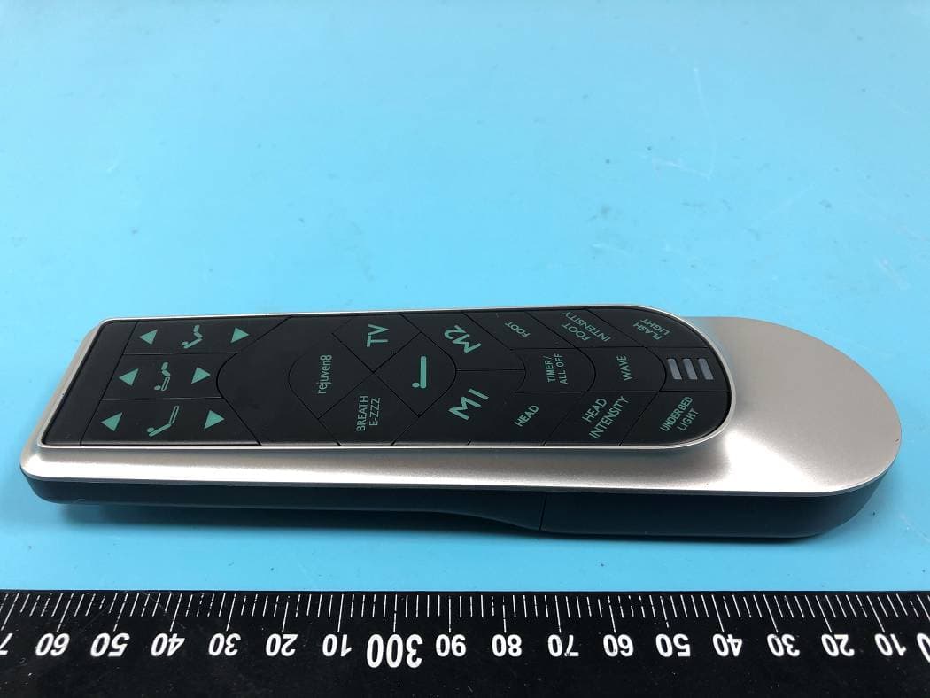
O3YENS
Jul 21, 2020RF-ENHANCE-ANGLE
Equipment Class
DXX - Part 15 Low Power Communication Device Transmitter
O3YENH
Jun 28, 2020RF-ENHANCE-STRAIGHT
Equipment Class
DXX - Part 15 Low Power Communication Device Transmitter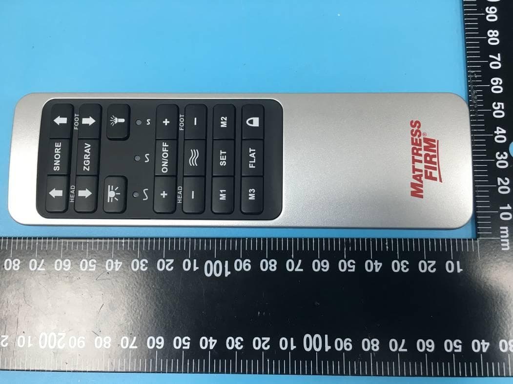
O3YF105820
Apr 29, 2020RF-1058
Equipment Class
DXX - Part 15 Low Power Communication Device Transmitter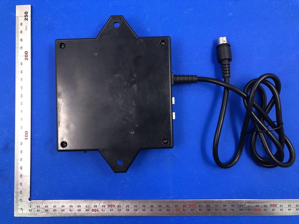
O3YCU458-2
Apr 14, 2020Control Unit CU458-2
Equipment Class
DTS - Digital Transmission System
O3YRF202A
Nov 04, 2015HE200
Equipment Class
DXX - Part 15 Low Power Communication Device Transmitter