O5UKS110BPC to Stereo Link Base Station
Akoo.com, Inc.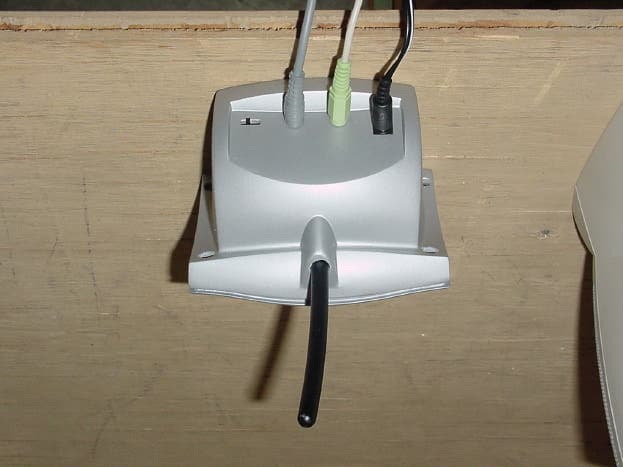
Click to zoom
Application Details
- Equipment Class
- DXX - Part 15 Low Power Communication Device Transmitter
- Date of Grant
- Sep 07, 2000
- Application Purpose
- Original Equipment
- Date of Application
- Sep 07, 2000
- Equipment Note
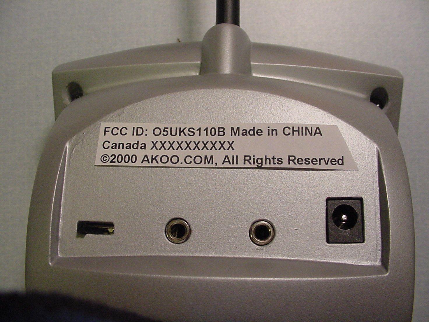
- PC to Stereo Link Base Station
- Frequency Range
- 905.00000000 - 908.00000000
- Company
- Akoo.com, Inc.
- Country
- United States
Documents & Files
Document Text
Text extracted from the exhibit documents filed with the FCC. Open a document above to read the original.
Users Manual
Akoo.com Kima operating instructions: The Kima system allows you to listen to music over the Internet on your home stereo system or FM radio. The Remote unit allows you to either directly connect to your stereo with RCA type cables or to retransmit the music over the FM band at 88.1 or 88.3 MHz. Use Instructions: 1) Connect the Audio out of your PC sound card, CD player or similar device to the Audio Input of the Kima Base unit. 2) Place the Kima Remote unit up to 1000 feet away, within 10 feet of your FM radio to use the FM transmitter function or connect the Stereo out connection of the Remote unit to the Audio In of your stereo receiver. 3) If you wish to use the FM transmitter feature, tune your radio to the same station as the Kima Remote unit is set to, either 88.1MHz or 88.3MHz. Battery Power: The Kima Base and Remote units can be powered either from a 6 Volt AC Adapter or from 4 AAA type batteries. NOTE: This device complies with part 15 of the FCC Rules. Operation is subject to the following two conditions: (1) This device may not cause harmful interference, and (2) this device must accept any interference received, including interference that may cause undesired operation. In order to maintain compliance with FCC regulations shielded cables must be used with this equipment. Operation with non-approved equipment or unshielded cables is likely to result in interference to radio & television reception. CAUTION: Changes or modifications not expressly approved by Akoo.com may void the users authority to operate this equipment. The following is provided for users of the Kima remote without FM Band transmitter option: NOTE: This equipment has been tested and found to comply with the limits for a Class B digital device, pursuant to part 15 of the FCC Rules. These limits are designed to provide reasonable protection against harmful interference in a residential installation. This equipment generates, uses and can radiate radio frequency energy and, if not installed and used in accordance with the instructions, may cause harmful interference to radio communications. However, there is no guarantee that interference will not occur in a particular installation. If this equipment does cause harmful interference to radio or television reception, which can be determined by turning the equipment off and on, the user is encouraged to try to correct the interference by one or more of the following measures: -Reorient or relocate the receiving antenna. -Increase the separation between the equipment and receiver. -Connect the equipment into an outlet on a circuit different from that to which the receiver is connected. -Consult the dealer or an experienced radio/TV technician for help.
Test Report
Compliance Worldwide, Inc. - 357 Main Street - Sandown, NH 03873 (603) 887 3903 Fax 887 6445 http://www.cw-inc.com TEST NUMBER - 268-00 FEDERAL COMMUNICATIONS COMMISSION PART 15.249 CERTIFICATION TESTING 902 - 928 MHz Subpart C - Intentional Radiators for Akoo.com 2500 North Harlem Avenue Elmwood Park, IL 60707 202-418-2470 of Kima 900 MHz base unit FCCID#: O5UKS110B on July 19, 2000 Tested by _____________________________________ Clifton P. Brick Reviewed by _____________________________________ Larry K. Stillings Page of 37 Compliance Worldwide, Inc. - 357 Main Street - Sandown, NH 03873 (603) 887 3903 Fax 887 6445 http://www.cw-inc.com 2 TEST NUMBER - 268-00 Akoo.com Kima - 900 MHz base unit TABLE OF CONTENTS • Test Description • Test Results and Conclusions • Test Procedures • Part 15 Subpart C Test Limits • Measurement Uncertainty Budget and Calculations • Test Facility Description • Test Setup and Connection Information • Test Measurements and Results Radiated Measurements Radiated Output Power & Occupied Bandwidth Conducted Measurements • Notes and Comments • Photographs Radiated Test Setup (Front & Rear) Conducted Test Setup (Front & Rear) Exterior and Interior Photographs of Product Page of 37 Compliance Worldwide, Inc. - 357 Main Street - Sandown, NH 03873 (603) 887 3903 Fax 887 6445 http://www.cw-inc.com 3 TEST NUMBER - 268-00 Akoo.com Kima - 900 MHz base unit TEST DESCRIPTION 1. TEST OBJECTIVE To test the Kima 900 MHz base unit to FCC Part 15.249, Subpart C limits and write a report. 2. E.U.T. DESCRIPTION GENERAL The Kima 900 MHz base unit is a transmitter that connects to the audio out port of a sound card on a PC. The purpose of this is to allow transmission of MP3 music technology to the remote receiver in the 902-928 MHz band. SERIAL NUMBERS: Pre-Production Prototype. Page of 37 Compliance Worldwide, Inc. - 357 Main Street - Sandown, NH 03873 (603) 887 3903 Fax 887 6445 http://www.cw-inc.com 4 TEST NUMBER - 268-00 Akoo.com Kima - 900 MHz base unit TEST RESULTS AND CONCLUSIONS PRODUCT TESTED - Kima MODEL NUMBER - 900 MHz base unit RADIATED TEST RESULTS The test results show that the emissions radiated from this equipment are in compliance with FCC Rules, Part 15, Subpart C, Section 15.209. OCCUPIED BANDWIDTH & OUTPUT POWER The test results show that the occupied bandwidth and output power of this equipment are in compliance with FCC Rules, Part 15, Subpart C, Section 15.239. CONDUCTED TEST RESULTS The test results show that the emissions conducted through the power line from this equipment are in compliance with FCC Rules, Part 15, Subpart C, Section 15.207. ANALYSIS AND CONCLUSIONS Based upon the radiated and conducted measurements we find that this equipment is within the limits of the FCC Rules, Part 15, Subpart C. NOTES (Special conditions unique to this test) NONE. Page of 37 Compliance Worldwide, Inc. - 357 Main Street - Sandown, NH 03873 (603) 887 3903 Fax 887 6445 http://www.cw-inc.com 5 TEST NUMBER - 268-00 Akoo.com Kima - 900 MHz base unit TEST PROCEDURES 1. TEST EQUIPMENT A. HP 8546A (9 kHz - 6.5 GHz) EMI Receiver w/ RF Filter Section, S/N 3704A00323 / 3650A00360. Calibration Date 7-18-2000, calibrated annually. B. HP 8593E (9 kHz - 26.5 GHz) Spectrum Analyzer, S/N 3829A03887. Calibration Date 9-3-1999, calibrated annually. C. Electro-Metrics BiConical Antenna, Model EM6912A, S/N 149. Calibration Date 2-22-2000, calibrated annually. D. Electro-Metrics Log Periodic Antenna, Model EM-6950, S/N 1017. Calibration Date: 2-22-2000, calibrated annually. E. Com-Power Corporation Horn Antenna, Model AH-118, S/N 10078. Calibration Date: 8-16-1999, calibrated annually. F. HP 1 - 26.5 GHz Preamplifier, Model 08449B, S/N 3008A01323. Calibration Date: 9-29-1999, calibrated annually. G. LISN, Compliance Worldwide, Model 50 μH / 50 ohm, S/N 100. Calibration Date 2-22-2000, calibrated annually. 2. FREQUENCY RANGE TO BE SCANNED. A. Radiated Test from 30 MHz to 40 GHz (or the 10 th harmonic of the highest frequency whichever is lower). B. Conducted Test from 450 kHz to 30 MHz. Page of 37 Compliance Worldwide, Inc. - 357 Main Street - Sandown, NH 03873 (603) 887 3903 Fax 887 6445 http://www.cw-inc.com 6 TEST NUMBER - 268-00 Akoo.com Kima - 900 MHz base unit 3. TEST PROCEDURES. Radiated test procedure The EUT, associated cables and peripheral devices are placed on the supporting table and any support equipment is placed off the site. The EUT is turned on and any necessary operating or test software installed and allowed to warm up. The frequency band from 30 MHz to 40 GHz is scanned. When an emission is found the emission is maximized by varying the bundle position of the connecting cables, the antenna height, the antenna polarization (vertical and horizontal) and the table orientation (360 degrees). The maximum reading is recorded and the next signal is searched for. Conducted test procedure The power line of the EUT is connected to the LISN (Line Impedance Stabilization Network). A measurement of the emissions are made from the power line for both phase and neutral on the analyzer in the frequency range from 450 kHz to 30 MHz. The maximum readings are recorded for each phase. All measurements are made according to the procedures defined in: "ANSI C63.4-1992 Standard Methods of Measurement of Radio Noise Emissions from Low-Voltage Electrical and Electronics Equipment in the Range of 9 kHz to 40 GHz, American National Standard for (ISBN 1- 55937-215-5). Page of 37 Compliance Worldwide, Inc. - 357 Main Street - Sandown, NH 03873 (603) 887 3903 Fax 887 6445 http://www.cw-inc.com 7 TEST NUMBER - 268-00 Akoo.com Kima - 900 MHz base unit PART 15 SUBPART C TEST LIMITS 1. 15.209, 15.235 & 15.249 Radiation Limits (Quasi-Peak): Frequency MHz Distance meters Limit dBμV/m Limit μV/m 1.705 - 30 30 29.5* 30* 30 - 88 3 40.0 100 49.82 - 49.90 3 80.0* 10,000* 88 - 216 3 43.5 150 216 - 960 3 46.0 200 902 - 928 3 94.0* 50,000* 960 - 1000 3 54.0 500 1000 - 40000 3 54.0* 500* *NOTE: Average Limits 2. 1…
Text truncated - open the document above for the full version.
Test Report
Page 1 of 3 Compliance Worldwide, Inc. - 357 Main Street - Sandown, NH 03873 (603) 887 3903 Fax 887 6445 http://www.cw-inc.com 9/5/2000 Dear Jon Curtis, Below I have answered each of your questions in bold below and attached also please find exhibits where appropriate. Thanks and Best Regards, Clifton P. Brick FCC ID# O5UKS110B 1. For your information only: The DCD code on the 731 form item 6(a) is only for transmitters below 1705 kHz, not 1705 MHz as you have indicated. I am considering this device to be a DXX Low Power Communications Device Transmitter. No response is needed to this item. Thank You. 2. A shielded cable was used during test on the audio port of the device. 15.27(c) requires that either such a cable be shipped with the device or that the user's manual inform the user of the requirement to use shielded cables on the audio input port. Please add a suitable statement to the user's manual or tell us that an shielded audio cable is shipped with the unit. An appropriate statement was added, please see the attached revised instruction. 3. You state on page 13 of the test report that a video bandwidth of 300KHz was used. Did you use this VBW with above 1GHz where a Resolution Bandwidth of 1MHz is required or did you use a different VBW above 1GHz? The bandwidth of 1MHz was used above 1GHz. Page 2 of 3 Compliance Worldwide, Inc. - 357 Main Street - Sandown, NH 03873 (603) 887 3903 Fax 887 6445 http://www.cw-inc.com 4. Your tabular data for radiated emissions says the units are dBuV. Shouldn't these be reported in units of dBuV/m? How do you account for antenna factor? If your instrument automatically adds in the antenna factor, do you also include a cable loss factor? What about the preamp? You are correct, the data is actually in dBuV/m . Antenna factors are added automatically via an amplitude correction file. Cable loss is compensated automatically via an amplitude correction file. The preamp is internal to the instrument and is compensated automatically. 5. Please confirm that the antenna is directly soldered to the PC board and that there is no connector in line with the antenna. If there is a connector describe how it meets the unique connector requirements of 15.203. Yes, the antenna is soldered directly to the PCB. 6. I think there is another PCB within the chassis. If there is, please submit photos of both sides of any circuit boards not already submitted in the test report. The schematic diagrams list an “LED_PCB". This was an oversight, please find the photos attached. 7. Please confirm that the label is "permanently attached" and tell us the method. Please confirm that the point size of the typeface used is larger than 8pt. The Label will be molded into the rear housing and the font will meet the required minimum. See photo attached. 8. 15.31(e) requires that the power input to the device be varied from 85% to 115% of nominal while the effect on fundamental radiated emissions field strength. Please tell me where this is covered in your test report or submit data showing that the effect of power variations on the unit's fundamental emission. The units operate on 3V regulated DC at the board level. The input voltage was varied +/- 15% and no output power change was noted. Page 3 of 3 Compliance Worldwide, Inc. - 357 Main Street - Sandown, NH 03873 (603) 887 3903 Fax 887 6445 http://www.cw-inc.com 9. I see no data for the harmonics of the fundamental. I would have expected data for at least the second and third. Please confirm that there is no data and if that is the case, please submit your noisefloor reading in field strength at the measurement distance to confirm that you can observe to the limit level. Please find attached a plot of my OATS ambient in the range requested. 10. In future submissions please send the equipment photos as two separate exhibits labeled exterior and interior photos. I will extract them from this application and submit them separately this time. The FCC wants me to submit them as separate files. No Problem. Attachments: FCC label location photo Revised Instructions Ambient 1-4.6GHz
Test Report
Compliance Worldwide, Inc. - 357 Main Street - Sandown, NH 03873 (603) 887 3903 Fax 887 6445 http://www.cw-inc.com TEST NUMBER - 268-00 FEDERAL COMMUNICATIONS COMMISSION PART 15.249 CERTIFICATION TESTING 902 - 928 MHz Subpart C - Intentional Radiators for Akoo.com 2500 North Harlem Avenue Elmwood Park, IL 60707 202-418-2470 of Kima 900 MHz base unit FCCID#: O5UKS110B on July 19, 2000 Tested by _____________________________________ Clifton P. Brick Reviewed by _____________________________________ Larry K. Stillings Page of 37 Compliance Worldwide, Inc. - 357 Main Street - Sandown, NH 03873 (603) 887 3903 Fax 887 6445 http://www.cw-inc.com 2 TEST NUMBER - 268-00 Akoo.com Kima - 900 MHz base unit TABLE OF CONTENTS • Test Description • Test Results and Conclusions • Test Procedures • Part 15 Subpart C Test Limits • Measurement Uncertainty Budget and Calculations • Test Facility Description • Test Setup and Connection Information • Test Measurements and Results Radiated Measurements Radiated Output Power & Occupied Bandwidth Conducted Measurements • Notes and Comments • Photographs Radiated Test Setup (Front & Rear) Conducted Test Setup (Front & Rear) Exterior and Interior Photographs of Product Page of 37 Compliance Worldwide, Inc. - 357 Main Street - Sandown, NH 03873 (603) 887 3903 Fax 887 6445 http://www.cw-inc.com 3 TEST NUMBER - 268-00 Akoo.com Kima - 900 MHz base unit TEST DESCRIPTION 1. TEST OBJECTIVE To test the Kima 900 MHz base unit to FCC Part 15.249, Subpart C limits and write a report. 2. E.U.T. DESCRIPTION GENERAL The Kima 900 MHz base unit is a transmitter that connects to the audio out port of a sound card on a PC. The purpose of this is to allow transmission of MP3 music technology to the remote receiver in the 902-928 MHz band. SERIAL NUMBERS: Pre-Production Prototype. Page of 37 Compliance Worldwide, Inc. - 357 Main Street - Sandown, NH 03873 (603) 887 3903 Fax 887 6445 http://www.cw-inc.com 4 TEST NUMBER - 268-00 Akoo.com Kima - 900 MHz base unit TEST RESULTS AND CONCLUSIONS PRODUCT TESTED - Kima MODEL NUMBER - 900 MHz base unit RADIATED TEST RESULTS The test results show that the emissions radiated from this equipment are in compliance with FCC Rules, Part 15, Subpart C, Section 15.209. OCCUPIED BANDWIDTH & OUTPUT POWER The test results show that the occupied bandwidth and output power of this equipment are in compliance with FCC Rules, Part 15, Subpart C, Section 15.239. CONDUCTED TEST RESULTS The test results show that the emissions conducted through the power line from this equipment are in compliance with FCC Rules, Part 15, Subpart C, Section 15.207. ANALYSIS AND CONCLUSIONS Based upon the radiated and conducted measurements we find that this equipment is within the limits of the FCC Rules, Part 15, Subpart C. NOTES (Special conditions unique to this test) NONE. Page of 37 Compliance Worldwide, Inc. - 357 Main Street - Sandown, NH 03873 (603) 887 3903 Fax 887 6445 http://www.cw-inc.com 5 TEST NUMBER - 268-00 Akoo.com Kima - 900 MHz base unit TEST PROCEDURES 1. TEST EQUIPMENT A. HP 8546A (9 kHz - 6.5 GHz) EMI Receiver w/ RF Filter Section, S/N 3704A00323 / 3650A00360. Calibration Date 7-18-2000, calibrated annually. B. HP 8593E (9 kHz - 26.5 GHz) Spectrum Analyzer, S/N 3829A03887. Calibration Date 9-3-1999, calibrated annually. C. Electro-Metrics BiConical Antenna, Model EM6912A, S/N 149. Calibration Date 2-22-2000, calibrated annually. D. Electro-Metrics Log Periodic Antenna, Model EM-6950, S/N 1017. Calibration Date: 2-22-2000, calibrated annually. E. Com-Power Corporation Horn Antenna, Model AH-118, S/N 10078. Calibration Date: 8-16-1999, calibrated annually. F. HP 1 - 26.5 GHz Preamplifier, Model 08449B, S/N 3008A01323. Calibration Date: 9-29-1999, calibrated annually. G. LISN, Compliance Worldwide, Model 50 μH / 50 ohm, S/N 100. Calibration Date 2-22-2000, calibrated annually. 2. FREQUENCY RANGE TO BE SCANNED. A. Radiated Test from 30 MHz to 40 GHz (or the 10 th harmonic of the highest frequency whichever is lower). B. Conducted Test from 450 kHz to 30 MHz. Page of 37 Compliance Worldwide, Inc. - 357 Main Street - Sandown, NH 03873 (603) 887 3903 Fax 887 6445 http://www.cw-inc.com 6 TEST NUMBER - 268-00 Akoo.com Kima - 900 MHz base unit 3. TEST PROCEDURES. Radiated test procedure The EUT, associated cables and peripheral devices are placed on the supporting table and any support equipment is placed off the site. The EUT is turned on and any necessary operating or test software installed and allowed to warm up. The frequency band from 30 MHz to 40 GHz is scanned. When an emission is found the emission is maximized by varying the bundle position of the connecting cables, the antenna height, the antenna polarization (vertical and horizontal) and the table orientation (360 degrees). The maximum reading is recorded and the next signal is searched for. Conducted test procedure The power line of the EUT is connected to the LISN (Line Impedance Stabilization Network). A measurement of the emissions are made from the power line for both phase and neutral on the analyzer in the frequency range from 450 kHz to 30 MHz. The maximum readings are recorded for each phase. All measurements are made according to the procedures defined in: "ANSI C63.4-1992 Standard Methods of Measurement of Radio Noise Emissions from Low-Voltage Electrical and Electronics Equipment in the Range of 9 kHz to 40 GHz, American National Standard for (ISBN 1- 55937-215-5). Page of 37 Compliance Worldwide, Inc. - 357 Main Street - Sandown, NH 03873 (603) 887 3903 Fax 887 6445 http://www.cw-inc.com 7 TEST NUMBER - 268-00 Akoo.com Kima - 900 MHz base unit PART 15 SUBPART C TEST LIMITS 1. 15.209, 15.235 & 15.249 Radiation Limits (Quasi-Peak): Frequency MHz Distance meters Limit dBμV/m Limit μV/m 1.705 - 30 30 29.5* 30* 30 - 88 3 40.0 100 49.82 - 49.90 3 80.0* 10,000* 88 - 216 3 43.5 150 216 - 960 3 46.0 200 902 - 928 3 94.0* 50,000* 960 - 1000 3 54.0 500 1000 - 40000 3 54.0* 500* *NOTE: Average Limits 2. 1…
Text truncated - open the document above for the full version.
Contact Information
Applicant
Ronald G Pace(VP of Product Development)
Technical Contact
Compliance Worldwide Inc.Larry Stillings
[email protected]6038873903
357 Main Street · Sandown, New Hampshire · United States
Non-Technical Contact
Compliance Worldwide Inc.Larry Stillings
[email protected]6038873903
Test Firm
Compliance Worldwide, Inc.Larry Stillings
Technical Specifications
| # | Rule Parts | Frequency Range | Power Output |
|---|---|---|---|
| 1 | 15C | 905 MHz - 908 MHz | - |
Other Applications from Akoo.com, Inc.

O5UFMLINK-1
Dec 05, 2002Wireless Music Adaptor
Equipment Class
DXX - Part 15 Low Power Communication Device Transmitter
O5UFMLINK
Oct 02, 2001Wireless Audio Adapter
Equipment Class
DXX - Part 15 Low Power Communication Device Transmitter
O5UKS110R
Sep 07, 2000PC to Stereo Link Remote Station
Equipment Class
DXT - Part 15 Low Power Transceiver, Rx Verified