O631050LD02Family Radio Service
Lionda Technology Co Ltd
Click to zoom
Application Details
- Equipment Class
- FRF - Part 95 Family Radio Face Held Transmitter
- Date of Grant
- Mar 27, 2002
- Application Purpose
- Original Equipment
- Date of Application
- Mar 27, 2002
- Equipment Note
- Family Radio Service
- Frequency Range
- 462.55000000 - 462.71000000
- Company
- Lionda Technology Co Ltd
- Country
- China
Documents & Files
Document Text
Text extracted from the exhibit documents filed with the FCC. Open a document above to read the original.
Users Manual
Makecertainyoureceivethebest performancefromyourCOMMUNICATOR. ReadthisOwner'sManualfirst. STOP 1050B MadeinChina COMMUNICATOR MODEL1050 OWNER'SMANUAL INSTALLATIONAND OPERATINGINSTRUCTIONS PLEASEREADTHIS OWNER'SMANUAL CAREFULLYBEFORE USE.KEEPFOR YOURREFERENCE. FORINFORMATION,PLEASESEEINSTALLATION SEPARATEQUICKSTARTGUIDE. 2001BellSouthCorporation 1 PRODUCTDESCRIPTION Contents SpecialFeatures 3 SpecialFeatures BELTCLIP(LOCATED ONTHEREAR) (Pg.8) EAR/MIC/CHARGER JACK(Pgs.8,14) UPBUTTON (VOLUME/CHANNEL) (Pgs.4,11-14,17) DOWNBUTTON (VOLUME/CHANNEL) (Pgs.4,11-14,17) PTTBUTTON (PUSHTOTALK) (Pgs.4,7,11-14) SCANBUTTON (Pg.4,13,14) SPEAKER (Pg.11) CALLBUTTON (Pg.4,12,14) MONITOR BUTTON (Pgs.4,11,12,17) MODEBUTTON (Pgs.4,10,12,13,17) POWERON/OFF BUTTON (Pgs.4,9,11,14) LCDSCREEN (Pgs.4,10-14,17) MIC (Pgs.6,11,17) ANTENNA (Pgs.5-7) BATTERYCOMPARTMENT (LOCATEDINSIDE) (Pgs.4,6,9) TXLEDINDICATOR (Pg.4,11,14) CareandSafety 7 FCCNotice 5 CareandSafety CAUTION WARNING DamagedANTENNA ForVehicleswithanAirBag PotentiallyExplosiveAtmospheres Batteries Batteries BlastingCapsandAreas CareandSafety GettingStarted RemovingtheBELTCLIP InstallingtheBELTCLIP ConnectingtheADAPTER AccessoryConnection notincludedwiththeunit.) Figure1Figure2 1 2 1 2 12 BC D E F A GH I 9 GettingStarted WARNING BATTERYINSTALLATION Figure3Figure4 GettingStarted LCDScreen 11 GettingStarted TurningtheUnitON TurningtheUnitOFF ReceivingaSignal TransmittingaSignal 12 Operation AdjustingSpeakerVolume 1212 ChangingCHANNELS MONITOR MODE/LOCKButton(FUNCTIONEDITING) Specifications Operation 14 Specifications 13 Operation 1516 ChangingtheCTCSSSUB-CHANNELS VOXSelection CHANNELSCAN BatteryChargeLevel/LowBatteryIndication SendingCALLTONES ToChargetheCOMMUNICATOR ifyouplantouseyourradioinanoisyorwindyenvironment. WarrantyWarranty 19 USElectronicsCONSUMERCENTER C/OSouthernBondedWarehouse 7137SouthlakeParkway Morrow,GA30260 Provideproofofthedateofpurchasewithinthepackage. Prepayallshippingcoststotheauthorizedservicecenter. Includeareturnshippingaddresswithinthepackage. Foryourreference: ModelNumber DateofPurchase NameofDealer CustomerServiceTelephoneNumber: 1-800-864-2199 Troubleshooting 17 Warranty 18 SYMPTOMSOLUTION Nopower. Reception isweak. PresstheUPbuttontoincreaseVOLUME. Thereceivingsignalmaybeweakand/oroutofrange. Ifthishappenspressthebutton.MON One-YearLimitedWarranty Rangeis limited. Batteriesmaybeweak. Sounddistortion problems. Cannotchange CTCSSsub- channels. Batteriesmaybeweak. Figure1Figure2 QuickStart Model1050 SeetheOwner'sManualforfulldetails. BATTERYINSTALLATION QuickStart 1.RemovetheBATTERYCOMPARTMENTCOVERfromtheBATTERY COMPARTMENT.SeeFigure1. (batteriesnotincluded)followingthepolaritiesasshowninFigure2. 3.ReinstalltheBATTERYCOMPARTMENTCOVER. TurningtheUnitON TurningtheUnitOFF ReceivingaSignal AdjustingtheSpeakerVolume TransmittingaSignal FIGURA1FIGURA2
External Photos
EUT External Photographs EUT - Top View EUT - Bottom View
ID Label/Location Info
FCC ID Labeling and Location Proposed FCC ID Labeling Proposed FCC ID Location Bottom Side of EUT FCC ID: O631050LD02 Proposed FCC ID Location
Internal Photos
EUT Internal Photographs EUT - Component View EUT - Solder View EUT - Transmitter View
Operational Description
LIONDA TECHNOLOGY COMPANY LIMITED Lionda Research and Development Center 1050 desc Page 1 1/5/02 CIRCUIT DESCRIPTION Model: 1050 (CTCSS) a. Receiver Section Radio Frequency signal received by the antenna (ANT1), passing through the Low Pass Filter (L2-L3, C30-C31). The RF signal is then amplified by Low Noise Amplifier Q2 and passes through a Band Pass Filter FL1 (465MHz). The filtered signal within the range of 462 MHz – 467 MHz is then mixed with the first local oscillator signal from the Voltage Controlled Oscillator (VCO) circuit (Q9, Q20-Q21, D7, L18) through Q11, a portion of VCO signal is then feedback to the PLL IC (IC5) for phase comparison generating a stable RX Frequency, the output signal is filtered by FL2 (10.7 MHz) which is the first Intermediate Frequency (IF) and is then amplified by Q14. The IF signal is fed to the discriminator IC (IC2) pin 16 which is then mixed with the second local oscillator supplied by crystal X2 (21.25 MHz) to produced and reduced second IF signal. Demodulated signal is recovered through correct adjustment of IF coil (L13) and the internal discriminator circuit of IC2. The recovered Audio signal is outputted at pin 9 of IC2 and then processed through filtering done by U3D circuit, the fully recovered audio signal is then further amplified by Power Amplifier U3A. An audible sound is therefore produce by the speaker SPK1, which can be varied from minimum to maximum through the key function (up/down) and process by the CPU IC6. b. Transmitter Section PTT switch (SW100) when pushed triggers the Transmitter Circuit “ON”, the voice signal generates by the surrounding noise passes through the Microphone MIC1 where mechanical to electrical transformation occurs, the electrical transformed signal is then filtered by a Band Pass Filter U3A, D, and C. The output signal is Modulated by a modulator circuit with a varactor diode D7 and L18. The external components from Q9-Q11 form a VCO Circuit, which generates the required oscillating frequency for transmission; a portion of this signal is feedback to the PLL IC2 pin 14 for phase comparison in order to produce a stabilized TX frequency. The modulated signal is then amplified by a Cascaded Amplifier Circuit Q7 and Q8 and again amplified by Q5 and Q6 to produce a sufficient Radio Frequency signal emitted by the Antenna (ANT1). c. Call Transmission By pushing the CALL key, a signal is detected by the CPU (IC6), a CALL data is then produced by the CPU. This data passes through the Band Pass Filter U1C and modulated by the varactor diode D4 and L1. The signal follows it’s conventional transmission section path through the antenna. d. Continuous Tone Coded Squelch Signal Protocol Once the unit is set to the corresponding Channel and CTCSS code at TX mode a tone is continuously generated from CPU through R96 and R103 and then passes through U1C for filtering and amplification. Then the Coded Tone signal follows its conventional transmission section path. During receiving mode once the Coded Tone signal matched with the set Code the CPU acknowledges and RX mute will disabled and RX will be active LIONDA TECHNOLOGY COMPANY LIMITED Lionda Research and Development Center 1050 desc Page 2 1/5/02 e. Battery Low Detection Battery Low Detection is controlled by the IC6 as detected on the LCD1, however a voltage divider circuit R50 and R51 serve as the stabilize reference voltage for the IC6 to process its detection. f. Squelch Detection Supported by the linear IC circuit (IC2), a variable resistor VR1 sets the level of detection and Diode D11 acts as a comparator circuit interface with the CPU IC6. g. Power Supply Supply voltage of 6 Volts dc is needed to power “ON” the whole circuitry, by four (4) batteries “AAA” size. FREQUENCY CHART CHANNEL FREQUENCY (MHz) CHANNEL FREQUENCY (MHz) 1 462.5625 8 467.5625 2 462.5875 9 467.5875 3 462.6125 10 467.6125 4 462.6375 11 467.6375 5 462.6625 12 467.6625 6 462.6875 13 467.6875 7 462.7125 14 467.7125 CTCSS CODE FREQUENCY CHART CODE FREQUENCY (Hz) CODE FREQUENCY (Hz) 1 67.0 20 131.8 2 71.9 21 136.5 3 74.4 22 141.3 4 77.0 23 146.2 5 79.7 24 151.4 6 82.5 25 156.7 7 85.4 26 162.2 8 88.5 27 167.9 9 91.5 28 173.8 10 94.8 29 179.9 11 97.4 30 186.2 12 100.0 31 192.8 13 103.5 32 203.5 14 107.2 33 210.7 15 110.9 34 218.1 16 114.8 35 225.7 17 118.8 36 233.6 18 123.0 37 241.8 19 127.3 38 250.3
Schematics
1050Nschematic.sch-1 - Sat Jan 05 15:59:14 2002 1050Nschematic.sch-2 - Sat Jan 05 15:17:11 2002
Test Report
Note: This test report is specially limited to the above client company and product model. It may not be duplicated without prior written consent of Bay Area Compliance Laboratory Corporation. This report must not be used by the client to claim product endorsement by NVLAP or any agency of the U.S. Government. FCC PART 95 EMI MEASUREMENT AND TEST REPORT For Lionda Technology Company Limited Block 2 Laodong 2 nd Industrial Area, Xixian, Baoan, Shenzhen, Guangdong, China 518102 FCC ID: O631050LD02 January 21, 2002 This Report Concerns: Original Report Equipment Type: Family Radio Service (FRS) Test Engineer: Jeff Lee Test Date: January 8, 2002 Reviewed By: John Y. Chan – Engineering Manager Prepared By: Bay Area Compliance Laboratory Corporation 230 Commercial Street Sunnyvale, CA 94085 Tel: (408) 732-9162 Fax: (408) 732 9164 Lionda Technology Company Limited FCC ID: O631050LD02 Report # R0201022 FCC Part 95 Test Report Page 2 of 21 TABLE OF CONTENTS 1 - GENERAL INFORMATION..................................................................................................................................4 1.1 PRODUCT DESCRIPTION FOR EQUIPMENT UNDER TEST (EUT) ..............................................................................4 1.2 OBJECTIVE.............................................................................................................................................................4 1.3 TEST METHODOLOGY............................................................................................................................................4 1.4 TEST FACILITY.......................................................................................................................................................4 1.5 TEST EQUIPMENT LIST...........................................................................................................................................5 1.6 LOCAL SUPPORT EQUIPMENT LIST AND DETAILS...................................................................................................5 1.7 EXTERNAL I/O CABLES LIST AND DETAILS...........................................................................................................5 2 - SYSTEM TEST CONFIGURATION.....................................................................................................................6 2.1 JUSTIFICATION.......................................................................................................................................................6 2.2 EUT EXERCISE SOFTWARE....................................................................................................................................6 2.3 SPECIAL ACCESSORIES...........................................................................................................................................6 2.4 SCHEMATICS / BLOCK DIAGRAM...........................................................................................................................6 2.5 EQUIPMENT MODIFICATIONS.................................................................................................................................6 2.6 CONFIGURATION OF TEST SYSTEM.........................................................................................................................7 2.7 TEST SETUP BLOCK DIAGRAM...............................................................................................................................7 3 - REQUIREMENTS OF PROVISIONS ...................................................................................................................8 3.1 GENERAL PROVISIONS...........................................................................................................................................8 3.2 REQUIREMENTS AND TEST SUMMARY...................................................................................................................8 3.3 LABELING REQUIREMENT......................................................................................................................................8 4 - EFFECTIVE RADIATED POWER.......................................................................................................................9 4.1 PROVISION APPLICABLE.........................................................................................................................................9 4.2 TEST PROCEDURE..................................................................................................................................................9 4.3 TEST EQUIPMENT.................................................................................................................................................10 4.4 TEST RESULTS.....................................................................................................................................................10 5 - MODULATION CHARACTERISTICS ..............................................................................................................11 5.1 PROVISION APPLICABLE.......................................................................................................................................11 5.2 TEST PROCEDURE................................................................................................................................................11 5.3 TEST EQUIPMENT.................................................................................................................................................11 5.4 TEST RESULTS.....................................................................................................................................................11 6 - OCCUPIED BANDWIDTH OF EMISSION.......................................................................................................14 6.1 PROVISION APPLICABLE.....................................................................................................................…
Text truncated - open the document above for the full version.
Test Setup Photos
Test Setup Photographs Radiated Emission Setup - Front View Radiated Emission Setup - Rear View
Contact Information
Applicant
Dan Coronia(Senior Engineer)
Test Firm
Bay Area Compliance LaboratoryJohn Chan
Technical Specifications
| # | Rule Parts | Frequency Range | Power Output | Emission | Tolerance |
|---|---|---|---|---|---|
| 1 | 95B | 462.55 MHz - 462.71 MHz | 126.00 mW | 11K0F3E | 2.3000000000 ppm |
Other Applications from Lionda Technology Co Ltd
O63GH5850HDLD03
May 23, 2004Digital Cordless Phone � Handset Unit
Equipment Class
DTS - Digital Transmission System
O63GH5815BALD04
Apr 15, 2004Analog Cordless Phone
Equipment Class
DXX - Part 15 Low Power Communication Device Transmitter
O63GH5815HALD04
Apr 15, 2004Analog Cordless Phone
Equipment Class
DXX - Part 15 Low Power Communication Device Transmitter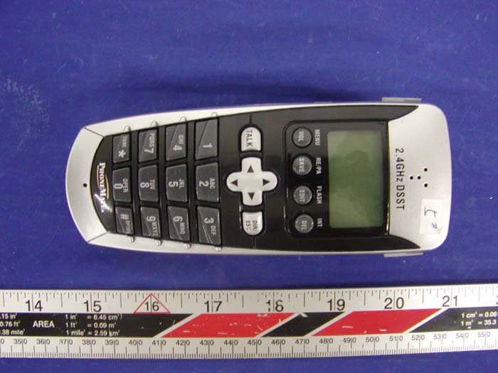
O63PM3320DLD04
Apr 05, 20042.4GHz Digital Spread-Spectrum Cordless Phone
Equipment Class
DTS - Digital Transmission System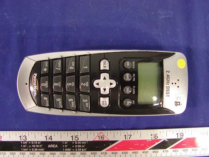
O63PM3375DLD04
Mar 29, 20042.4GHz Digital Spread-Spectrum Cordless Phone
Equipment Class
DTS - Digital Transmission System