O632730LD03FRS & GMRS
Lionda Technology Co Ltd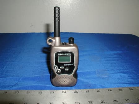
Click to zoom
Application Details
- Equipment Class
- FRF - Part 95 Family Radio Face Held Transmitter
- Date of Grant
- Jul 01, 2003
- Application Purpose
- Original Equipment
- Date of Application
- Jul 01, 2003
- Equipment Note
- FRS & GMRS
- Frequency Range
- 462.55000000 - 462.72500000
- Company
- Lionda Technology Co Ltd
- Country
- China
Documents & Files
Document Text
Text extracted from the exhibit documents filed with the FCC. Open a document above to read the original.
Users Manual
VX TX RX SC Mode Call GMRS/FRS P HILO COMMUNICATORMODEL 2730OWNER’S MANUALAND OPERATING INSTRUCTIONSPLEASE READTHIS OWNER SMANUAL CAREFULLYBEFORE USE.KEEP FOR YOURREFERENCE. Made in China LD Read this Owner’s Manual first to receive the best performance from the COMMUNICATOR. Operation on GMRS frequencies requires a license from the Federal Communications Commission (FCC) Website - http://wireless.fcc.gov/prs/genmbl.html Tel.: 1-800-418-3676 FOR “GETTING STARTED” INFORMATION, PLEASE SEE INSTALLATION INSTRUCTIONS ON PAGE 7 OR YOUR SEPARATE QUICK START GUIDE. © 2002 BellSouth Corporation Visit Us on the Web:www.uselectronics.info Contents Special Features Congratulations on your selection of a quality BellSouth Product . With proper care and adherence to the set-up and user instructionsin this Owner’s Manual, this unit will provide you with yearsof trouble-free service.BellSouth is committed to providing quality products that fit your needs. We would like to have any comments or suggestions youmight have on this product. You may mail your comments to: U.S. Electronics105 Madison AvenueNew York, NY 10016 PRODUCT DESCRIPTIONThe COMMUNICATOR is the newest generation in personal two-waycommunications. The COMMUNICATOR operates in a license-free radio band on the FRS channels 8 - 14 (no FCC license is needed for its operation), and on licensed GMRS/FRS channels 1 - 7, andGMRS channels 15 - 22 (see page 22 regarding licensing information).The C OMMUNICATOR is a lightweight, compact two-way communication device that can be used to communicate with family or friends at parks, shopping malls, sporting events, concerts -- anyindoor or outdoor activity!The COMMUNICATOR is compatible with other brands utilizing the same FRS frequency band (operating in the frequency range from462.5625 MHz to 467.7125 MHz) or same GMRS frequency band(operating in 462.5750 MHz to 462.7250 MHz). The COMMUNICATOR has 22 CHANNELS, including 7 FRS channels, 7 GMRS/FRS channels, and 8 GMRS channels (Fordetails, refer to page 15 CHANNEL TABLE.).Other features include ELECTRONIC VOLUME CONTROL andBATTERY SAVE CIRCUITRY.Please read this Owner's Manual carefully to get the most out ofyour GMRS/FRS COMMUNICATOR. NOTE: The maximum transmission range will vary depending on terrain and environment. Range will be greater in openfields, while range is shorter within and around buildings orlarge structures. This unit may not ensure privacy of communication. PreparationCOMMUNICATOR Controls - Location & Function................... 3FCC Notice................................................................................ 5Getting StartedRemoving the BELT CLIP......................................................... 7Installing the BELT CLIP........................................................... 7Battery Installation..................................................................... 8LCD Screen............................................................................... 9Turning the Unit ON................................................................... 10Turning the Unit OFF..................................................................10Adjusting Speaker Volume.........................................................10Receiving a Signal..................................................................... 10Transmitting a Signal................................................................. 10OperationChanging Channels................................................................... 11Monitor....................................................................................... 11MODE/BUTTON LOCK Button (FUNCTION EDITING)............ 11Changing the CTCSS Sub-channels......................................... 12VOX Selection............................................................................12TRANSMIT POWER SELECTION Mode.................................. 13CHANNEL SCAN....................................................................... 13Sending Call Tones.................................................................... 14Battery Level Indicator............................................................... 14Battery Charge Indication.......................................................... 14Connecting an Adapter.............................................................. 15Accessory Connection............................................................... 15Other InformationSpecifications............................................................................. 15Channel Table............................................................................ 16Troubleshooting......................................................................... 17Care and Maintenance...............................................................18Warranty..................................................................................... 20Licensing Information ................................................................22 VX TX RX SC Mode Call GMRS/FRS P HILO COMMUNICATOR Controls COMMUNICATOR Controls 3 4 3124 5 678 9 10 11 1213 14 161715 1. ANTENNA (Pgs. 6, 18, 19) 2. BELT CLIP (LOCATED ON THE REAR) (Pgs. 6-8) 3. LCD (Liquid Crystal Display) Screen: Displays current channel selection and other radio status symbols. (Pgs. 9-13, 17) 4. PTT (PUSH TO TALK) button - Press to make a call. (Pgs. 10-13) 5. MONITOR M button: Press to tune in and hold onto weak signals. (Pgs. 10, 11, 17) 6. UP ▲▲ button : Press to change channels and select FUNCTION in every editing mode. (Pgs. 11-14, 17) 7. DOWN ▼▼ button : Press to change channels and select FUNCTION in every editing mode. (Pgs. 11-14, 17) 8. CHARGE TERMINAL (LOCATED ON THE REAR) 9. BATTERY COMPARTMENT COVER LATCH (LOCATED ON THE REAR) - Secures BATTERY COMPARTMENTCOVER. (Pg. 8) 10. BATTERY COMPARTMENT (LOCATED ON THE REAR) - Houses four (4) 1.5V “AAA” alkaline or Ni-MH recharge- able batteries (not included with the package). (Pgs. 8, 19) 11. SPEAKER (Pg. 10) 12. MIC:…
Text truncated - open the document above for the full version.
Cover Letter(s)
Block 2 Laodong 2nd Industria Area, Xixian, Baoan, Shenzhen, China Tel.: 86-755-7917824/ 86-755-7902415, Fax: 86-755-7917944 June 28, 2003 Federal Communications Commission Authorization and Evaluation Division Confidentiality Request regarding application for certification of FCC ID: O632730LD03. Pursuant to Sections 0.457 and 0.459 of the Commission’s Rules, we hereby request confidential treatment of information accompanying this application as outlined below: • Schematics • Block Diagram • Circuit Description • BOM The above documents contain information for new GMRS/FRS (Two-Way Radio) technology and ideas, so we would like to prevent the use of this information by other companies. The applicant understands that pursuant to Section 0.457 of the Rules, disclosure of this application and all accompanying documentation will not be made before the date of the Grant for this application. Sincerely, _________________________________ Dan Coronia – Senior Approval Engineer
External Photos
Lionda Technology Co. Ltd. FCC ID: O632730LD03 APPENDIX C - EUT PHOTOGRAPHS Chassis - Front View Chassis – Rear View Lionda Technology Co. Ltd. FCC ID: O632730LD03 Chassis - Top View Chassis – Side View
ID Label/Location Info
APPENDIX A - FCC ID LABELING AND LOCATION Proposed FCC ID Labeling Proposed FCC ID Location Rear Side of EUT / Proposed Label Location FCC ID: O632730LD03 FCC ID: O632225LD02
Internal Photos
Lionda Technology Co. Ltd. FCC ID: O632730LD03 EUT – Board and Housing EUT - Component View Lionda Technology Co. Ltd. FCC ID: O632730LD03 EUT - Solder View Lionda Technology Co. Ltd. FCC ID: O632730LD03 EUT – Speaker EUT – Antenna Connection
Parts List/Tune Up Info
TUNE-UP PROCEDURE Model2730TUP Page 1 6/26/03 2730 1. TRANSMITTING 1.1 TX VCO ADJUSTMENT a) Connect the DC voltmeter to the test point 1 (TP1). b) Press the PTT Button. c) Adjust L18. d) Specification: 0.9Vdc +/- 0.3 V @ CH 1 1.2 FREQUENCY ADJUSTMENT a) Connect the frequency counter to ANT point. b) Adjust CV1. c) Specification: Tx Frequency +/- 200Hz 1.3 TX POWER CHECK a) Connect the RF level meter to the ANT point (RF impedance: 50Ω) b) Press the PTT button. c) Check the TX Power d) Specification: FRS : < 75mW GMRS : < 138mW e) Optimum Power Level: FRS = 80mW±1.0 GMRS = 145mW±2.0 1.4 MAX. DEVIATION ADJUSTMENT a) Connect the deviation meter to the ANT point. b) Apply the audio signal 1KHz, 4mVrms to the test point 7 (TP4 - MIC input) c) Observe the clipped signal on the scope. d) Adjust SVR1. e) Specification: 2.5KHz Dev +/- 0.15KHz 1.5 MODULATION SENSITIVITY ADJUSTMENT a) Connect the deviation meter to the ANT point. b) Apply the audio signal 1KHz, 8mVrms to the test point (TP4- MIC input). c) Adjust SVR1. d) Specification: 0.9-1.0KHz Dev 1.6 CALL DATA MODULATION SENSITIVITY CHECK a) Press the Call Button and observe the deviation meter to check the deviation. b) Specification: 1.8KHz +/- 0.5KHz 2. RECEIVING 2.1 RX VCO CHECK a) Connect the DC voltmeter to test point 1 (TP1). b) Check the DC voltage. c) Specification: 0.9Vdc +/- 0.6V @ CH 1 TUNE-UP PROCEDURE Model2730TUP Page 2 6/26/03 2730 2.2 QUAD COIL ADJUSTMENT a) Connect the DC voltmeter to the test point 3 (TP3). b) Adjust the IFT1. c) Specification: 1.5Vdc +/- 0.2V 2.3 SENSITIVITY CHECK a) Connect the Sinnader meter to test point 5 (TP5). b) Reduce the RF output level of signal generator to get the 12dB of Sinnader. c) Specification: <-116dBm 2.4 SQUELCH THRESHOLD POINT ADJUSTMENT a) Connect the DC voltmeter to test point 16. b) Same setup as the Sensitivity Check. c) Adjust the SVR1 to get the DC changing point. d) Specification: 7dB +/- 1dB 2.5 SPEAKER OUTPUT LEVEL CHECK a) Connect the Audio level meter to test point 5 (TP5). b) Connect the 8Ω load to test point 5 (TP5). c) Press the volume button till its maximum level. d) Adjust the modulation deviation of RF signal generator. e) Check the clipping start deviation & level. f) Specification: Clipping start deviation = >0.6KHz Level = -2 +/- 4 dBm NOTE: 1. Press PTT button continuously when checking TRANSMITTING parameters. 2. Press the Monitor button to disable the RX power saving when the RX is not stable. 3. OTHER PARAMETER CHECKING 3.1 LOW BATTERY DETECT VOLTAGE CHECK a) Change the voltage until the Battery icon is flashing on the LCD. b) Check the voltage. c) Specification: 4.2Vdc +/- 0.3V
Test Report
Note: This test report is specially limited to the above client company and product model. It may not be duplicated without prior written consent of Bay Area Compliance Laboratory Corporation. This report must not be used by the client to claim product endorsement by NVLAP or any agency of the U.S. Government. FCC PART 95 EMI MEASUREMENT AND TEST REPORT For Lionda Technology Company Limited Block 2 Laodong 2 nd Industrial Area, Xixian, Baoan, Shenzhen, Guangdong, China 518102 FCC ID: O632730LD03 2003-06-10 This Report Concerns: Original Report Equipment Type: FRS & GMRS Test Engineer: Benjamin Jing / Report Number: R0305141 Test Date: 2003-05-28 Reviewed By: Hans Mellberg / Prepared By: Bay Area Compliance Laboratory Corporation 230 Commercial Street Sunnyvale, CA 94085 Tel: (408) 732-9162 Fax: (408) 732 9164 Lionda Technology Co. Ltd. FCC ID: O632730LD03 Report # R0305141RptFCC Part 95 Test ReportPage 2 of 23 TABLE OF CONTENTS 1 - GENERAL INFORMATION.................................................................................................................................................3 1.1 PRODUCT DESCRIPTION FOR EQUIPMENT UNDER TEST (EUT).........................................................................................3 1.2 OBJECTIVE................................................................................................................................................................................3 1.3 RELATED GRANT/SUBMISSION..............................................................................................................................................3 1.4 TEST METHODOLOGY.............................................................................................................................................................3 1.5 TEST FACILITY.........................................................................................................................................................................3 1.6 TEST EQUIPMENT LIST............................................................................................................................................................4 2 - SYSTEM TEST CONFIGURATION..................................................................................................................................5 2.1 JUSTIFICATION.........................................................................................................................................................................5 2.2 EUT TEST CONFIGURATION..................................................................................................................................................5 2.3 SPECIAL ACCESSORIES............................................................................................................................................................5 2.4 SCHEMATICS / BLOCK DIAGRAM..........................................................................................................................................5 2.5 EQUIPMENT MODIFICATIONS.................................................................................................................................................5 2.6 CONFIGURATION OF TEST SYSTEM.......................................................................................................................................6 2.7 TEST SETUP BLOCK DIAGRAM..............................................................................................................................................6 3 - REQUIREMENTS OF PROVISIONS................................................................................................................................7 3.1 REQUIREMENTS AND TEST SUMMARY.................................................................................................................................7 3.2 LABELING REQUIREMENT......................................................................................................................................................7 4 - EFFECTIVE RADIATED POWER.....................................................................................................................................8 4.1 PROVISION APPLICABLE.........................................................................................................................................................8 4.2 TEST PROCEDURE....................................................................................................................................................................8 4.3 TEST EQUIPMENT.....................................................................................................................................................................9 4.4 TEST RESULTS..........................................................................................................................................................................9 5 - MODULATION CHARACTERISTICS...........................................................................................................................10 5.1 PROVISION APPLICABLE.......................................................................................................................................................10 5.2 TEST PROCEDURE..................................................................................................................................................................10 5.3 TEST EQUIPMENT..................................................................................................................................................................10 5.4 TEST RESULTS........................................................................................................................................................................10 6 - OCCUPIED BANDWIDTH OF EMISSION...................................................................................................................13 6.1 P…
Text truncated - open the document above for the full version.
Test Setup Photos
Lionda Technology Co. Ltd. FCC ID: O632730LD03 APPENDIX B - TEST SETUP PHOTOGRAPHS Radiated Emission - Front View Radiated Emission - Rear View
Contact Information
Applicant
Dan Coronia(Senior Engineer)
Test Firm
Bay Area Compliance LaboratoryJohn Chan
Technical Specifications
| # | Rule Parts | Frequency Range | Power Output | Emission | Tolerance |
|---|---|---|---|---|---|
| 2 | 95A | 462.55 MHz - 462.725 MHz | 138.00 mW | 11K0F3E | 2.5 ppm |
Other Applications from Lionda Technology Co Ltd
O63GH5850HDLD03
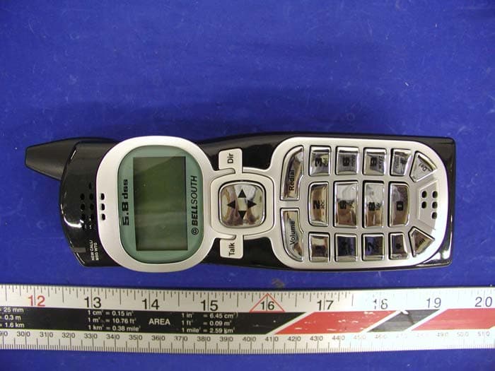
May 23, 2004Digital Cordless Phone � Handset Unit
Equipment Class
DTS - Digital Transmission System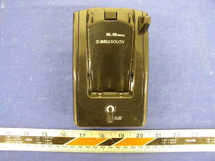
O63GH5815BALD04
Apr 15, 2004Analog Cordless Phone
Equipment Class
DXX - Part 15 Low Power Communication Device Transmitter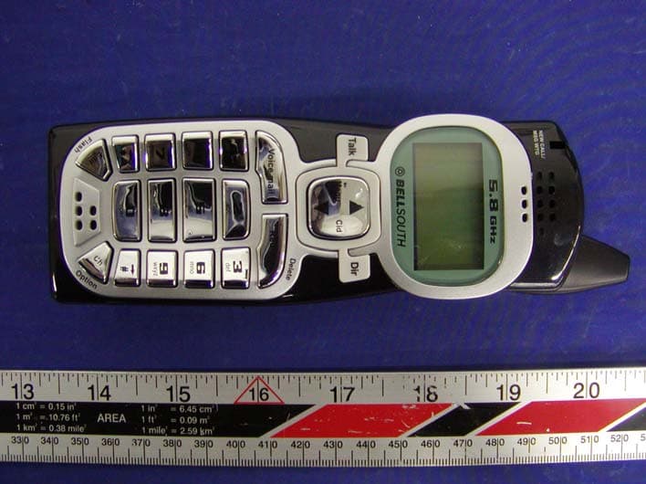
O63GH5815HALD04
Apr 15, 2004Analog Cordless Phone
Equipment Class
DXX - Part 15 Low Power Communication Device Transmitter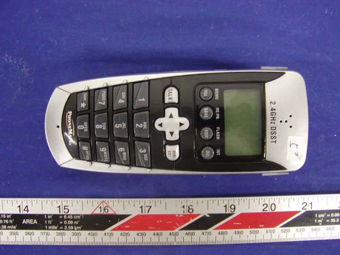
O63PM3320DLD04
Apr 05, 20042.4GHz Digital Spread-Spectrum Cordless Phone
Equipment Class
DTS - Digital Transmission System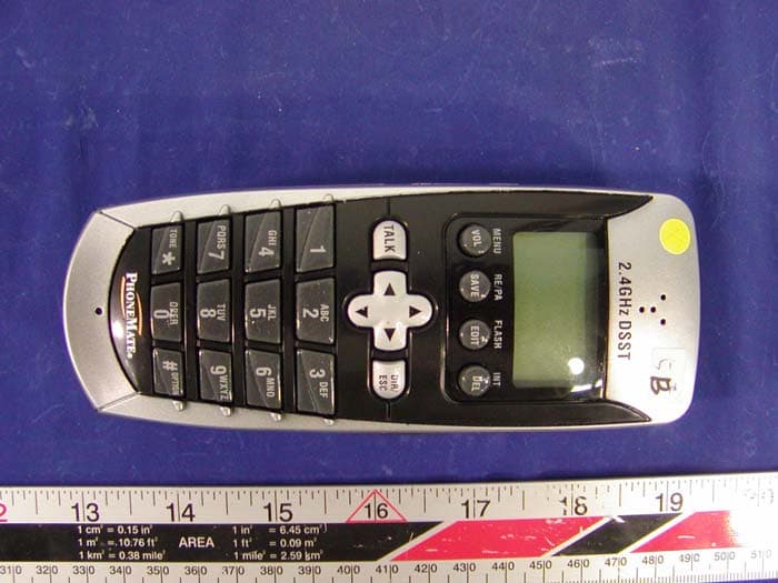
O63PM3375DLD04
Mar 29, 20042.4GHz Digital Spread-Spectrum Cordless Phone
Equipment Class
DTS - Digital Transmission System