O63LD01
Lionda Technology Co Ltd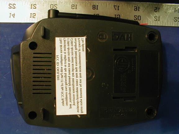
Click to zoom
Application Details
- Equipment Class
- DSS - Part 15 Spread Spectrum Transmitter
- Date of Grant
- Nov 13, 2001
- Application Purpose
- Original Equipment
- Date of Application
- Jul 11, 2001
- Frequency Range
- 2401.92000000 - 2475.00000000
- Company
- Lionda Technology Co Ltd
- Country
- China
Documents & Files
Document Text
Text extracted from the exhibit documents filed with the FCC. Open a document above to read the original.
External Photos
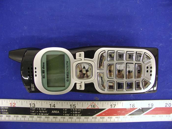
EUT – Base Top View EUT – Base Bottom View EUT – Base Rear View EUT – Handset Top View EUT – Handset Back View
ID Label/Location Info
FCC ID Label for Base Unit Rear Side of EUT / Proposed FCC ID Location FCC ID: O63LD01 This device complies with Part 15 of the FCC Rules. Operation is subject to the following two conditions: (1) this device may not cause harm- ful interference, and (2) this device must accept any interference received, including interference that may cause undesired operation. Privacy of communicaton may not be ensured when using this phone 1.0" 2.1875 FCC ID Label Handset Back Side If the EUT is too small, the FCC statement could be presented in the user manual. Generally, appendix B contains one copy of user manual. The following is one sample of the FCC Statement: “ This device complies with part 15 of the FCC Rules. Operation is subject to the following two conditions: (1) This device may not cause harmful interference, and (2) this device must accept any interference received, including interference that may cause undesired operation. Privacy of Communication may not be ensured when using the phone.” FCC ID: O63LD01
Internal Photos
Base Open Cover View Handset Open Cover View Base Main Board Component View Base Main Board Solder View Base RF Board Component View Handset RF Board Solder View
RF Exposure Info
RF SAFETY REQUIREMENTS TO 2.1091 According to section 3 of Supplement C to OET Bulleting 65, Part 15 Transmitters are categorically excluded from Routine Environmental Evaluation by measurement or precise computations unless otherwise required by the Commissions. The unit under evaluation has an external antenna of 0 dBi gain with a measured output power of 3.5 mW Watts at the antenna terminals. Due to the low power of the EUT, environmental evaluation should be deemed unnecessary since the EUT’s operational frequency range is 2400-2483.05 MHz and the Effective radiated power (ERP) is considerably less than 3 Watts. A warning statement is also included in the user manual. }} IMPORTANT NOTE To comply with FCC RF exposure compliance requirements, the antenna installation and device operating configurations must be satisfied. The Spread Spectrum Portable Transmitter operating with the device and its antenna at a separation distance less than 2.5 cm from all persons.
Test Report
LIONDA TECHNOLOGY CO., LTD FCC ID: O63LD01 Report # R0105244 Page 46 of 93 FCC Part 15.247 Test Report LIONDA TECHNOLOGY CO., LTD FCC ID: O63LD01 Report # R0105244 Page 47 of 93 FCC Part 15.247 Test Report 8 – POWER DENSITY 8.1 Standard Applicable According to §15.247 (d), for direct sequence systems, the peak power spectral density conducted from the intentional radiator to the antenna shall not be greater than 8 dBm in any 3 kHz band during any time interval of continuous transmission. 8.2 Measurement Procedure 1. Check the calibration of the measuring instrument using either an internal calibrator or a known signal from an external generator. 2. Position the EUT was set without connection to measurement instrument. Turn on the EUT and connect its antenna terminal to measurement instrument via a low loss cable. Then set it to any one measured frequency within its operating range, and make sure the instrument is operated in its linear range. 3. Adjust the center frequency of SA on any frequency be measured and set SA to zero span mode. And then, set RBW and VBW of spectrum analyzer to proper value. 4. Repeat above procedures until all frequencies measured were complete. 8.3 Test Results Please refer to the following plot(s). Page Reference Power Density Base Handset Test Result Low Channel Page 48 Page 51 Passed Middle Channel Page 49 Page 52 Passed High Channel Page 50 Page 53 Passed LIONDA TECHNOLOGY CO., LTD FCC ID: O63LD01 Report # R0105244 Page 48 of 93 FCC Part 15.247 Test Report LIONDA TECHNOLOGY CO., LTD FCC ID: O63LD01 Report # R0105244 Page 49 of 93 FCC Part 15.247 Test Report LIONDA TECHNOLOGY CO., LTD FCC ID: O63LD01 Report # R0105244 Page 50 of 93 FCC Part 15.247 Test Report LIONDA TECHNOLOGY CO., LTD FCC ID: O63LD01 Report # R0105244 Page 51 of 93 FCC Part 15.247 Test Report LIONDA TECHNOLOGY CO., LTD FCC ID: O63LD01 Report # R0105244 Page 52 of 93 FCC Part 15.247 Test Report LIONDA TECHNOLOGY CO., LTD FCC ID: O63LD01 Report # R0105244 Page 53 of 93 FCC Part 15.247 Test Report LIONDA TECHNOLOGY CO., LTD FCC ID: O63LD01 Report # R0105244 Page 54 of 93 FCC Part 15.247 Test Report 9 - ANTENNA REQUIREMENT 9.1 Standard Applicable For intentional device, according to § 15.203, an intentional radiator shall be designed to ensure that no antenna other than that furnished by the responsible party shall be used with the device. And according to § 15.247 (1), if transmitting antennas of directional gain greater than 6 dBi are used the power shall be reduced by the amount in dB that the directional gain of the antenna exceeds 6 dBi. 9.2 Antenna Connected Construction The directional gain of antenna used for transmitting is 0 dBi, and the antenna connector is designed with permanent attachment and no consideration of replacement. Please see EUT photo for details. LIONDA TECHNOLOGY CO., LTD FCC ID: O63LD01 Report # R0105244 Page 55 of 93 FCC Part 15.247 Test Report 10 – RF SAFETY REQUIREMENTS TO 2.1091 According to section 3 of Supplement C to OET Bulleting 65, Part 15 Transmitters are categorically excluded from Routine Environmental Evaluation by measurement or precise computations unless otherwise required by the Commissions. The unit under evaluation has an external antenna of 0 dBi gain with a measured output power of 3.5 mW Watts at the antenna terminals. Due to the low power of the EUT, environmental evaluation should be deemed unnecessary since the EUT’s operational frequency range is 2400-2483.05 MHz and the Effective radiated power (ERP) is considerably less than 3 Watts. A warning statement is also included in the user manual. LIONDA TECHNOLOGY CO., LTD FCC ID: O63LD01 Report # R0105244 Page 56 of 93 FCC Part 15.247 Test Report 11 – SPURIOUS RADIATED EMISSION DATA 11.1 Measurement Uncertainty All measurements involve certain levels of uncertainties, especially in field of EMC. The factors contributing to uncertainties are spectrum analyzer, cable loss, antenna factor calibration, antenna directivity, antenna factor variation with height, antenna phase center variation, antenna factor frequency interpolation, measurement distance variation, site imperfections, mismatch (average), and system repeatability. Based on NIS 81, The Treatment of Uncertainty in EMC Measurements, the best estimate of the uncertainty of a radiation emissions measurement at BACL is +4.0 dB. 11.2 EUT Setup The radiated emission tests were performed in the open area 3-meter test site, using the setup in accordance with the ANSI C63.4 - 1992. The specification used was the FCC 15 Subpart C limits. The EUT was connected to a 110 VAC / 60 Hz power source and it was placed on the back edge of the test table. The simulator was placed on one side of the EUT, and the telephone was placed on the other side of the EUT. The rear of the EUT and peripherals were placed flushed with the rear of the tabletop. The spacing between the peripherals was 10 centimeters. Input / Output cables were draped along the edge of the test table and bundle when necessary. 11.3 Spectrum Analyzer Setup According to FCC Rules, 47 CFR §15.33 (a) (1), the system was tested to 24000 MHz. During the radiated emission test, the spectrum analyzer was set with the following configurations: Start Frequency...................................................................30 MHz Stop Frequency...................................................................24000 MHz Sweep Speed........................................................................Auto IF Bandwidth........................................................................1 MHz Video Bandwidth.................................................................1 MHz Quasi-Peak Adapter Bandwidth........................................120 kHz Quasi-Peak Adapter Mode................................................Normal Resolution Bandwidth........................................................1MHz LIONDA TECHNOLOGY CO., LTD FCC ID: O63LD01 Report # R0105244 Page 57 of 93 FCC Part 15.247 …
Text truncated - open the document above for the full version.
Test Report
Note: This report may not be duplicated without prior written consent of Bay Area Compliance Laboratory Corporation. This report must not be used by the client to claim product endorsement by NVLAP or any agency of the U.S. Government. FCC PART 15 Subpart C EMI MEASUREMENT AND TEST REPORT For LIONDA TECHNOLOGY CO., LTD. Block 2 Laodong 2 nd Industrial Area, Baoan Shenzhen, China 518102 FCC ID: O63LD01 June 7, 2001 This Report Concerns: Original Report Equipment Type: Cordless Telephone System – Household Appliances Test Engineer: Hien Pham Test Date: June 4, 2001 Reviewed By: John Y. Chan – Engineering Manager Prepared By: Bay Area Compliance Laboratory Corporation 230 Commercial Street, Suite 2 Sunnyvale, CA 94085 Tel: (408) 732-9162 Fax: (408) 732 9164 LIONDA TECHNOLOGY CO., LTD FCC ID: O63LD01 Report # R0105244 Page 2 of 93 FCC Part 15.247 Test Report TABLE OF CONTENTS 1 - GENERAL INFORMATION.................................................................................................................................................4 1.1 PRODUCT DESCRIPTION FOR EQUIPMENT UNDER TEST (EUT)........................................................................................4 1.2 OBJECTIVE................................................................................................................................................................................4 1.3 RELATED SUBMITTAL(S)/GRANT(S).....................................................................................................................................4 1.4 TEST METHODOLOGY..............................................................................................................................................................4 1.5 TEST FACILITY.........................................................................................................................................................................4 1.6 TEST EQUIPMENT LIST............................................................................................................................................................5 1.7 EQUIPMENT UNDER TEST (EUT)...........................................................................................................................................5 1.8 POWER SUPPLY AND LINE FILTERS.......................................................................................................................................5 1.8 SUPPORT EQUIPMENT LIST AND DETAILS............................................................................................................................5 1.9 EXTERNAL I/O CABLING LIST AND DETAILS......................................................................................................................6 2 - SYSTEM TEST CONFIGURATION..................................................................................................................................7 2.1 DESCRIPTION OF TEST CONFIGURATION..............................................................................................................................7 2.2 CONFIGURATION OF TEST SYSTEM.......................................................................................................................................8 2.3 TEST SETUP BLOCK DIAGRAM (BASE).................................................................................................................................9 2.4 EQUIPMENT MODIFICATIONS...............................................................................................................................................11 3 - SUMMARY OF TEST RESULTS......................................................................................................................................12 4 - CONDUCTED OUTPUT POWER MEASUREMENT................................................................................................13 4.1 STANDARD APPLICABLE.......................................................................................................................................................13 4.2 MEASUREMENT PROCEDURE................................................................................................................................................13 4.3 MEASUREMENT RESULT.......................................................................................................................................................13 5 – 6 DB BANDWIDTH...............................................................................................................................................................20 5.1 STANDARD APPLICABLE.......................................................................................................................................................20 5.2 MEASUREMENT PROCEDURE................................................................................................................................................20 5.3 MEASUREMENT DATA...........................................................................................................................................................20 6 – SPURIOUS EMISSION........................................................................................................................................................27 6.1 STANDARD APPLICABLE.......................................................................................................................................................27 6.2 MEASUREMENT PROCEDURE................................................................................................................................................27 6.3 MEASUREMENT DATA...........................................................................................................................................................27 7 100 KHZ BANDWIDTH OF BAND EDGES MEASUREMENT................................................................................40 7.1 STANDARD APPLICABLE......…
Text truncated - open the document above for the full version.
Test Report
LIONDA TECHNOLOGY CO., LTD FCC ID: O63LD01 Report # R0105244 Page 26 of 93 FCC Part 15.247 Test Report LIONDA TECHNOLOGY CO., LTD FCC ID: O63LD01 Report # R0105244 Page 27 of 93 FCC Part 15.247 Test Report 6 – SPURIOUS EMISSION 6.1 Standard Applicable According to §15.209 (f) and §15.33(a), in some cases the emissions from an intentional radiator must be measured to beyond the tenth harmonic of the highest fundamental frequency designed to be emitted by the intentional radiator because of the incorporation f a digital device. If measurements above the tenth harmonic are so required, the radiated emissions above the tenth harmonic shall comply with the general radiated emission limits applicable to the incorporated digital device, as shown in §15.109 and as based on the frequency of the emission being measured, or, except for emissions contained in the restricted frequency bands shown in §15.205, the limit on spurious emissions specified for the intentional radiator, whichever is the higher limit. 6.2 Measurement Procedure 1. Check the calibration of the measuring instrument (SA) using either an internal calibrator or a known signal from an external generator. 2. Position the EUT as shown in figure 4 without connection to measurement instrument. Turn on the EUT and connect its antenna terminal to measurement instrument via a low loss cable. Then set it to any one measured frequency within its operating range, and make sure the instrument is operated in its linear range. 3. Set the SA on Max-Hold Mode, and then keep the EUT in transmitting mode. Record all the signals from each channel until each one has been recorded. 4. Set the SA on View mode and then plot the result on SA screen. 5. Repeat above procedures until all frequencies measured were complete. 6.3 Measurement Data Page Reference Base Handset Test Results Number of Hopping Channel Frequencies Page 28-30 Page 31-33 Pass LIONDA TECHNOLOGY CO., LTD FCC ID: O63LD01 Report # R0105244 Page 28 of 93 FCC Part 15.247 Test Report LIONDA TECHNOLOGY CO., LTD FCC ID: O63LD01 Report # R0105244 Page 29 of 93 FCC Part 15.247 Test Report LIONDA TECHNOLOGY CO., LTD FCC ID: O63LD01 Report # R0105244 Page 30 of 93 FCC Part 15.247 Test Report LIONDA TECHNOLOGY CO., LTD FCC ID: O63LD01 Report # R0105244 Page 31 of 93 FCC Part 15.247 Test Report LIONDA TECHNOLOGY CO., LTD FCC ID: O63LD01 Report # R0105244 Page 32 of 93 FCC Part 15.247 Test Report LIONDA TECHNOLOGY CO., LTD FCC ID: O63LD01 Report # R0105244 Page 33 of 93 FCC Part 15.247 Test Report LIONDA TECHNOLOGY CO., LTD FCC ID: O63LD01 Report # R0105244 Page 34 of 93 FCC Part 15.247 Test Report LIONDA TECHNOLOGY CO., LTD FCC ID: O63LD01 Report # R0105244 Page 35 of 93 FCC Part 15.247 Test Report LIONDA TECHNOLOGY CO., LTD FCC ID: O63LD01 Report # R0105244 Page 36 of 93 FCC Part 15.247 Test Report LIONDA TECHNOLOGY CO., LTD FCC ID: O63LD01 Report # R0105244 Page 37 of 93 FCC Part 15.247 Test Report LIONDA TECHNOLOGY CO., LTD FCC ID: O63LD01 Report # R0105244 Page 38 of 93 FCC Part 15.247 Test Report LIONDA TECHNOLOGY CO., LTD FCC ID: O63LD01 Report # R0105244 Page 39 of 93 FCC Part 15.247 Test Report LIONDA TECHNOLOGY CO., LTD FCC ID: O63LD01 Report # R0105244 Page 40 of 93 FCC Part 15.247 Test Report 7 100 kHz BANDWIDTH OF BAND EDGES MEASUREMENT 7.1 Standard Applicable According to §15.247(c), if any 100 kHz bandwidth outside these frequency bands, the radio frequency power that is produced by the modulation products of the spreading sequence, the information sequence and the carrier frequency shall be either at least 20 dB below that in any 100 kHz bandwidth within the band that contains the highest level of the desired power or shall not exceed the general levels specified in § 15.209(a), whichever results in the lesser attenuation. 7.2 Measurement Procedure 1. Check the calibration of the measuring instrument using either an internal calibrator or a known signal from an external generator. 2. Position the EUT without connection to measurement instrument. Turn on the EUT and connect its antenna terminal to measurement instrument via a low loss cable. Then set it to any one measured frequency within its operating range, and make sure the instrument is operated in its linear range. 3. Set both RBW and VBW of spectrum analyzer to 300 kHz with a convenient frequency span including 100kHz bandwidth from band edge. 4. Measure the highest amplitude appearing on spectral display and set it as a reference level. Plot the graph with marking the highest point and edge frequency. 5. Repeat above procedures until all measured frequencies were complete. 7.3 Test Results Page Reference Band Edge Bandwith Base Handset Test Result Low Channel Page 41 Page 44 Passed Middle Channel Page 42 Page 45 Passed High Channel Page 43 Page 46 Passed LIONDA TECHNOLOGY CO., LTD FCC ID: O63LD01 Report # R0105244 Page 41 of 93 FCC Part 15.247 Test Report LIONDA TECHNOLOGY CO., LTD FCC ID: O63LD01 Report # R0105244 Page 42 of 93 FCC Part 15.247 Test Report LIONDA TECHNOLOGY CO., LTD FCC ID: O63LD01 Report # R0105244 Page 43 of 93 FCC Part 15.247 Test Report LIONDA TECHNOLOGY CO., LTD FCC ID: O63LD01 Report # R0105244 Page 44 of 93 FCC Part 15.247 Test Report LIONDA TECHNOLOGY CO., LTD FCC ID: O63LD01 Report # R0105244 Page 45 of 93 FCC Part 15.247 Test Report
Test Report
1 - Conducted Output Power Measurement 1.1 Standard Applicable For frequency hopping, according to §15.247(b) (2), the maximum peak output power of the transmitter shall not exceed 1 Watt. 1.2 Measurement Procedure 1. Place the EUT on a table and set it in transmitting mode. 2. Remove the antenna from the EUT and then connect a low loss RF cable from the antenna port to a power meter. 1.3 Measurement Result Page Reference Peak Output Power BaseHandset Test Result Low Channel -174.6Passed Middle Channel -14.35.3Passed High Channel -13.85.1Passed 1.4 Test Equipment List ManufacturerModel Number Serial Number Cal Due Date HP 432A1507A1403802/05/2001
Test Setup Photos
Base Conducted Emission Setup – Front View Base Conducted Emission Setup – Rear View Base Radiated Emission Setup – Front View Base Conducted Emission Setup – Rear View Handset Radiated Emission Setup – Front View Handset Radiated Emission Setup – Rear View
Contact Information
Applicant
Dan Coronia(Senior Engineer)
Technical Contact
.Bay Area Compliance Laboratory Corp.John Chan
[email protected]408 732 9162
230 Commercial Street · Sunnyvale, California · United States
Non-Technical Contact
Bay Area Compliance Laboratory Corp.Rita Cai
[email protected]408 732 9162
Test Firm
Bay Area Compliance LaboratoryJohn Chan
Technical Specifications
| # | Rule Parts | Frequency Range | Power Output |
|---|---|---|---|
| 1 | 15C | 2.40 GHz - 2.48 GHz | 3.40 mW |
Other Applications from Lionda Technology Co Ltd
O63GH5850HDLD03
May 23, 2004Digital Cordless Phone � Handset Unit
Equipment Class
DTS - Digital Transmission System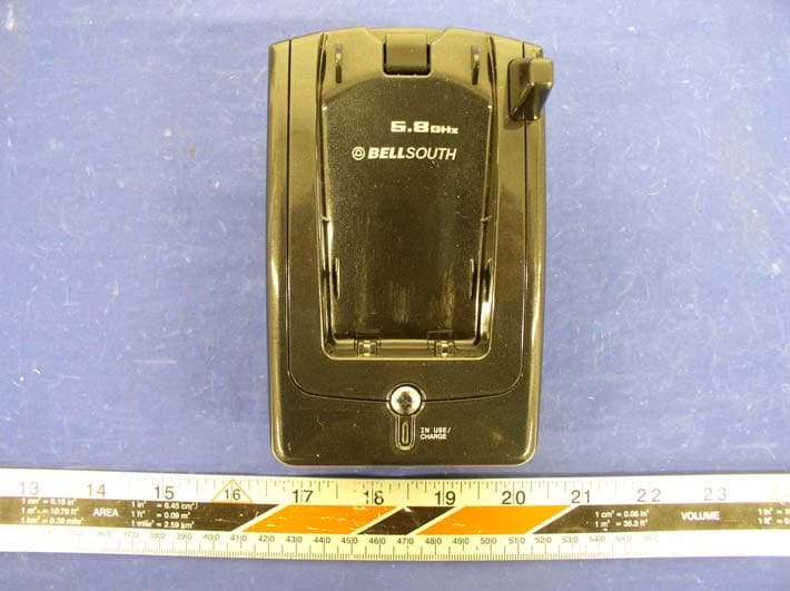
O63GH5815BALD04
Apr 15, 2004Analog Cordless Phone
Equipment Class
DXX - Part 15 Low Power Communication Device Transmitter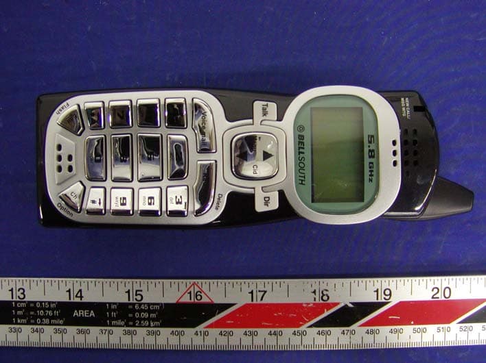
O63GH5815HALD04
Apr 15, 2004Analog Cordless Phone
Equipment Class
DXX - Part 15 Low Power Communication Device Transmitter
O63PM3320DLD04
Apr 05, 20042.4GHz Digital Spread-Spectrum Cordless Phone
Equipment Class
DTS - Digital Transmission System
O63PM3375DLD04
Mar 29, 20042.4GHz Digital Spread-Spectrum Cordless Phone
Equipment Class
DTS - Digital Transmission System