O63MH9002LD02900MHz Filtered Snd w/ 40 Chnnl Autoscan Crdls Phn
Lionda Technology Co Ltd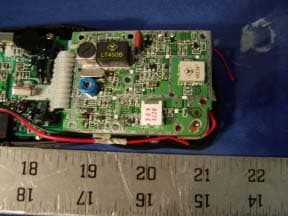
Click to zoom
Application Details
- Equipment Class
- DXX - Part 15 Low Power Communication Device Transmitter
- Date of Grant
- Mar 03, 2002
- Application Purpose
- Original Equipment
- Date of Application
- Mar 03, 2002
- Equipment Note
- 900MHz Filtered Snd w/ 40 Chnnl Autoscan Crdls Phn
- Frequency Range
- 926.12000000 - 927.29000000
- Company
- Lionda Technology Co Ltd
- Country
- China
Documents & Files
Document Text
Text extracted from the exhibit documents filed with the FCC. Open a document above to read the original.
Users Manual
CORDLESS TELEPHONE Model MH9002 OWNER'S MANUAL INSTALLATION AND OPERATING INSTRUCTIONS PLEASE READ THIS MANUAL CAREFULLY BEFORE USE. KEEP FOR YOUR REFERENCE. 4 P AGE T ALK SCA N R EDI AL © 1995, 2002 BellSouth Corporation Special Features ongratulations on your selection of a quality BellSouth Product. With proper care, and by following the setup and user instructions in this manual, this unit will provide you with years of trouble free service. BellSouth is committed to providing quality products that fit your needs. We would like to have any comments or suggestions you might have on this product. You may mail your comments to: U.S. Electronics 105 Madison Avenue New York, NY 10016 When examining your new BellSouth cordless telephone, you will find an array of special features including: Filtered Sound™ System - Receives considerably less noise than conventional cordless telephones because of a special circuit which delivers the clearest possible reception. 40 Channel Autoscan - Press the button on the HANDSET to find and lock on to the clearest channel for any call. Telephone Number Storage - Store up to 10 frequently called numbers. Desk or Wall Mount - Use this equipment as a desk phone or as a wall phone. TONE or PULSE Dialing - Use this phone for either TONE (push-button) or PULSE (rotary) dialing. Automated Functions - Redial the last number called, speed dial 10 numbers and automatic STANDBY mode. Security - Ensures greater privacy because a built-in security code with 65,536 combinations prevents use of your telephone line by another nearby cordless phone. Dependable Battery - Recharge your BATTERY PACK many times with the built-in charger. The battery low warning tone tells you when the BATTERY PACK needs recharging. (See page 11.) Special Services - Use the FLASH button to access special services such as Call Waiting supplied by your telephone company or company switchboard. STANDBY Mode - When in STANDBY mode (ON-HOOK), the phone is capable of receiving a call. When the HANDSET is on the BASE UNIT, it is automatically in the STANDBY mode (ON-HOOK). When the HANDSET is off the BASE UNIT, it remains in the STANDBY mode until you activate the button. Battery Power Saver - Once fully charged, in STANDBY mode, and with the RINGER SWITCH in the “ON” position, the HANDSET can receive/send calls for a maximum of five days without the need for recharging. Length of charge depends on frequency of use. HANDSET Volume Control Switch - Select the receiver volume level (HI, MID, LOW). HEADSET JACK - Your telephone can utilize a headset for hands-free communication. BELT CLIP - Use the BELT CLIP to hang your HANDSET on your belt. C 1.HANDSET ANTENNA 7. IN USE/BATT LOW INDICATOR Pg. 7, 8, 11 3. REDIAL BUTTON Pg. 9 2. TALK BUTTON Pg. 5, 7, 8, 9, 13 6. MEMO BUTTON Pg. 8, 9 10. VOLUME CONTROL (HI, MID, LOW) SWITCH 12. CHARGE CONTACTS 8. SCAN BUTTON Pg. 7,10, 13, 16 4. PAUSE BUTTON Pg. 9 9. FLASH BUTTON 5. HEADSET JACK Pg. 10 11. TONE BUTTON 4 TALK SCANREDIAL 1.HANDSET ANTENNA 2. Button: Press to answer an incoming call or to place a call. Press to end a call. 3. Button : Press to REDIAL the last number you called. 4.PAUSE Button: Press to insert a PAUSE while dialing. (You will need the PAUSE button to dial numbers which use an alternative Long Distance Access Code.) 5.HEADSET JACK: For connecting your headset plug to enjoy hands-free communication. (See page 10 for detail). 6.MEMO Button: Press to store phone numbers in memory or to call a number you have previously stored. 7.IN USE/BATT LOW LED Indicator: Lights up when the HANDSET is in TALK mode. Blinks when the battery charge is low. (See page 11 for detail.) 8. Button : Press to change the operating channel when you hear interference. 9.FLASH Button: Press to answer an incoming call if you have Call Waiting. 10.HANDSET Volume Control (hi, mid, low) Switch: Select the receiver volume level (HI, MID, LOW). 11.TONE Button: Press to change the dialing mode from PULSE to TONE. 12.CHARGE CONTACTS: For charging the BATTERY PACK inside the HANDSET. We recommend cleaning the CHARGE CONTACTS periodically with a damp cloth. IMPORTANT In order to get maximum life from the HANDSET BATTERY PACK, be sure to charge the HANDSET for 12 hours before initial use. HANDSET Controls 1. TELEPHONE LINE CONNECTION JACK Pg. 4, 6, 13 3. TONE/PULSE SELECT SWITCH Pg. 5, 13 2. POWER-IN CONNECTION JACK Pg. 4 6. CHARGE TERMINALS 5. BASE UNIT ANTENNA 8. IN USE/CHARGE LED INDICATOR Pg. 8 7. PAGE BUTTON PAGE 4. HANDSET RETAINER TAB BASE UNIT Controls 1.TELEPHONE LINE CONNECTION JACK 2.POWER-IN CONNECTION JACK 3.TONE/PULSE Select Switch 4.HANDSET RETAINER TAB: For holding the HANDSET to rest securely in the BASE UNIT CRADLE during wall mounting. 5.BASE UNIT ANTENNA 6.CHARGE TERMINALS: For charging the BATTERY PACK inside the HANDSET. We recommend cleaning the CHARGE TERMINALS periodically with a damp cloth. 7. Button: Press to page the HANDSET. Press again to stop. 8.IN USE/CHARGE LED Indicator: Lights up when the HANDSET is in TALK mode or when the HANDSET is placed on the BASE UNIT for charging. IMPORTANT Placing your BASE UNIT near appliances such as televisions, refrigerators, radios, or microwave ovens may cause interference. Contents Safety Instructions.......................................................................................................................2 Getting Started.............................................................................................................................4 Desk Mounting..............................................................................................................................6 Wall Mounting...............................................................................................................................6 Basic Operation...........................................................................................................................7 Preparing for Use...........................…
Text truncated - open the document above for the full version.
Block Diagram
MH9002bbd.sch-1 - Wed Feb 20 17:34:56 2002 MH9002hbd.sch-1 - Wed Feb 20 17:37:08 2002
External Photos
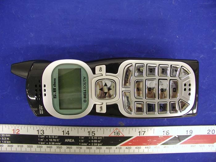
EUT EXTERNAL PHOTOGRAPHS Handset - Top View Handset - Bottom View Base - Top View Base - Bottom View
ID Label/Location Info
FCC PRODUCT LABELING AND WARNING STATEMENT FCC ID Label Specifications : Text is black or white in color and is left justified. Labels are silk- screened and shall be “permanently affixed” at a conspicuous location on the EUT. Proposed Label Location on EUT Bottom Side of Base/Proposed FCC ID Label Location / Handset FCC Warning Statement A FCC Warning Statement is provided in the product manual.
Internal Photos
EUT INTERNAL PHOTOGRAPHS Handset - Component View Handset - Solder View Handset - Transceiver Component View Handset - Transceiver Solder View Base - Component View Base - Solder View Base - Transceiver Component View Base - Transceiver Solder View
Operational Description
LIONDA TECHNOLOGY COMPANY LIMITEDLIONDA TECHNOLOGY COMPANY LIMITED ENGINEERING DEPARTMENTENGINEERING DEPARTMENT MH9002 desc Page 1 20-Feb-02 CIRCUIT DESCRIPTION Model: MH9002/MH9004 Base a. RF Transmitter Section – RF Board Compressed audio signal is frequency modulated through the varactor diode D3. Diode D3, choke coil L5 and the external components formed the voltage controlled oscillator circuit for the transmitter part. This circuit generates the TX VCO frequency. A portion of this signal is fed back to the PLL IC’s pin1 (FIN1) for phase comparison. Once the phase of oscillation stabilized, the PLL circuit generates the error voltage necessary for the VCO to oscillate at the desired transmitter’s RF frequency. The VCO circuit impedance is matched with the succeeding circuit through the transistor Q5 that also acts as the buffer amplifier. RF amplifier Q11 boosts the signal for transmission. This amplified RF signal is trimmed to the desired frequency band by BPF927 so as not to interfere with the receiver circuit. The transmitter RF signal is then propagated through the antenna. b. RF Receiver Section - RF Board The Base Uni t antenna receives RF signal. Band Pass Filter BPF903 trims the signal to the desirable frequency band. Transistor Q2 & Q3 is a low noise amplifier that boosts the RF signal to a specific level for mixing. PLL IC1 (KB8825) is used as a Universal Phase Lock Loop circuit. The frequency from the Voltage Controlled Oscillator (VCO) D1, and Q4, is fed back to the PLL IC through pin 16 (FIN2) for phase comparison. During channel scanning or turning the unit on, once the phase of oscillation stabilized (locked), the PLL circuit generates the first local oscillator frequency for down-converting the received RF signal into the first IF frequency 10.7MHz. This process is accomplished through the IF mixer circuit Q3. Q1 is used for matching the impedance of the mixer circuit with the succeeding circuits. The resulting IF signal is kept constant by the IF Filter FL1 to 10.7MHz which is then mixed with the second local oscillator frequency 11.150MHz (derived from X1 & C47) to produced a much lower IF frequency. This lower IF frequency if further filtered by IF Filter FL4 to produce a more stable signal of 450KHz. Quadrature signal detection is accomplished internally by the Narrow-band Detector IC2 (KA3361) with the IF coil L7. The recovered audio frequency can be taken from IC2 audio output pin9. Double conversion of received signal is utilized to improve the image frequency rejection of the unit. c. Transmitter Audio Section – Main Board Audio Frequency signal from the telephone line is compressed through the c ompressor part of IC4 to minimize the transmission noise. The degree of compression depends on the external RC combinations. AGC is also utilized by IC4 to avoid shock noise caused by abrupt change of audio levels. The compressed audio is filtered and amplified for better acoustical performance. 1 LIONDA TECHNOLOGY COMPANY LIMITEDLIONDA TECHNOLOGY COMPANY LIMITED ENGINEERING DEPARTMENTENGINEERING DEPARTMENT MH9002 desc Page 2 20-Feb-02 d. Receiver Audio Section – Main Board The compressed Audio Frequency signal is passed through passive RC filters for acoustic compliance. The filtered audio is then fed to the Compander IC4 for expansion thus retrieving the original Audio signal with noise filtered out. Q1 are used as buffer circuit. Transistor Q2 (A94) isolates the high-voltage telephone line to the rest of the circuit. Q2 (A94) is also used as a hybrid transformer to create a two-way path for audio transmission to and reception from the telephone line. Handset a. RF Transmitter Section – RF Board Refer to portion 1.a for this section. All circuit performance is the same except that Band Pass Filter BPF927 be changed to BPF903 for the handset transmission. b. RF Receiver Section – RF Board Refer to portion 1.b for this section. All circuit performance is the same except that Band Pass Filter BPF903 be changed to BPF927 for the handset reception. c. Transmitter Audio Section – Main Board Audio Frequency signal from the handset or from the headset microphone is compressed through the compressor part of IC2 to minimize the transmission noise. The degree of compression depends on the external RC combinations. AGC is also utilized by IC2 to avoid shock noise caused by abrupt change of audio levels. The compressed audio is filtered and amplified for better acoustical performance. Q5 is a switching transistor that controls the power supply for the TX RF part. d. Receiver Audio Section – Main Board The compressed Audio Frequency signal is passed through passive RC filters for acoustic compliance. The filtered audio is then fed to the Compander IC2 for expansion thus retrieving the original Audio signal with noise filtered out. Q3 act as audio amplifier to sufficiently drive the handset speaker. Q1, Q6 and Q8 are switching transistors that control the power supply for the RF part, the Compander part and the AF amplifier respectively. An earphone jack is provided for an optional headset unit for handsfree conversation on the handset. OTHERS (Handset) a. Charging and Reset Controls Recharging the handset battery is accomplished by putting the handset on the cradle. Q200 detects this action and sends a command to the CPU for proper exchange of security code. Switching SW4 to the RING OFF mode can extend Battery life. 2 3 LIONDA TECHNOLOGY COMPANY LIMITEDLIONDA TECHNOLOGY COMPANY LIMITED ENGINEERING DEPARTMENTENGINEERING DEPARTMENT MH9002 desc Page 3 20-Feb-02 b. Ring Detection When the handset receives the ring command from the base unit, the CPU will send buzzer signal to the ringer amplifier Q201 that drives the Buzzer. OTHERS (Base): a. Hook Switching and Dialing Hook switching and pulse dialing is accomplished by the Transistor Q3 (A44) which is controlled by the CPU. DTMF signal from the ladder circuit R65-R70 to the CPU is filtered and amplified by U1-D. b. Over-voltage P…
Text truncated - open the document above for the full version.
Schematics
MH9002schb.sch-1 - Wed Feb 20 17:25:00 2002 MH9002schh.sch-1 - Wed Feb 20 17:28:17 2002 MH9002rfb.sch-1 - Wed Feb 20 17:30:48 2002 MH9002rfh.sch-1 - Wed Feb 20 17:32:45 2002
Test Report
Note: This test report is specially limited to the above client company and the product model only. It may not be duplicated without prior written consent of Bay Area Compliance Laboratory Corporation. This report must not be used by the client to claim product endorsement by NVLAP or any agency of the U.S. Government. FCC PART 15 Subpart C EMI MEASUREMENT AND TEST REPORT For Lionda Technology Co., Ltd. Block 2 Laodong 2 nd Industrial Area, Xixiang, Baoan, Shenzhen, Guangdong, P.R.China 518102 FCC ID: O63MH9002LD02 March 1, 2002 This Report Concerns: Original Report Equipment Type: 900MHz Filtered Sound with 40 Channel Auto-scan Cordless Telephone Test Engineer: Benjamin Jing Test Date: February 22, 2002 Reviewed By: John Y. Chan – Engineering Manager Prepared By: Bay Area Compliance Laboratory Corporation 230 Commercial Street Sunnyvale, CA 94085 Tel (408) 732-9162 Fax (408) 732-9164 Lionda Technology Co., Ltd. FCC ID: O63MH9002LD02 Report # MH9002Rpt Page 2 of 18 FCC Part 15 Subpart C Test Report TABLE OF CONTENTS 1 - GENERAL INFORMATION..................................................................................................................................3 1.1 PRODUCT DESCRIPTION FOR EQUIPMENT UNDER TEST (EUT) ..............................................................................3 1.2 OBJECTIVE.............................................................................................................................................................3 1.3 RELATED SUBMITTAL(S)/GRANT(S) ......................................................................................................................3 1.4 TEST METHODOLOGY............................................................................................................................................3 1.5 TEST FACILITY.......................................................................................................................................................3 1.6 TEST EQUIPMENT LIST...........................................................................................................................................4 1.8 LOCAL SUPPORT EQUIPMENT LIST AND DETAILS...................................................................................................5 1.9 EXTERNAL I/O CABLING LIST AND DETAILS.........................................................................................................5 2 - SYSTEM TEST CONFIGURATION.....................................................................................................................6 2.1 DESCRIPTION OF TEST CONFIGURATION................................................................................................................6 2.2 CONFIGURATION OF TEST SYSTEM (BASE)............................................................................................................7 2.3 TEST SETUP BLOCK DIAGRAM...............................................................................................................................7 2.4 EQUIPMENT MODIFICATIONS.................................................................................................................................7 3 - CONDUCTED EMISSIONS TEST DATA............................................................................................................8 3.1 MEASUREMENT UNCERTAINTY..............................................................................................................................8 3.2 EUT SETUP............................................................................................................................................................8 3.3 SPECTRUM ANALYZER SETUP................................................................................................................................8 3.4 TEST PROCEDURE..................................................................................................................................................9 3.5 SUMMARY OF TEST RESULTS.................................................................................................................................9 3.6 CONDUCTED EMISSIONS TEST DATA.....................................................................................................................9 3.7 PLOT OF CONDUCTED EMISSIONS TEST DATA.....................................................................................................10 4 - RADIATED EMISSION DATA ...........................................................................................................................11 4.1 MEASUREMENT UNCERTAINTY............................................................................................................................11 4.2 EUT SETUP..........................................................................................................................................................11 4.3 SPECTRUM ANALYZER SETUP..............................................................................................................................11 4.4 TEST PROCEDURE................................................................................................................................................12 4.5 CORRECTED AMPLITUDE & MARGIN CALCULATION...........................................................................................12 4.6 SUMMARY OF TEST RESULTS...............................................................................................................................13 4.7 RADIATED EMISSIONS TEST RESULT DATA.........................................................................................................14 5 - BAND EDGES TESTING .....................................................................................................................................17 5.1 TEST PROCEDURE........................................................................................................................................…
Text truncated - open the document above for the full version.
Test Setup Photos
Conducted and Radiated Setup Photographs Base Conducted Emission Photograph - Front View Base Conducted Emission Photograph - Rear View Base Radiated Emission Photograph - Front View Base Radiated Emission Photograph - Rear View Handset Radiated Emission Photograph - Front View Handset Radiated Emission Photograph - Rear View
Contact Information
Applicant
Dan Coronia(Senior Engineer)
Test Firm
Bay Area Compliance LaboratoryJohn Chan
Technical Specifications
| # | Rule Parts | Frequency Range | Power Output |
|---|---|---|---|
| 2 | 15C | 926.12 MHz - 927.29 MHz | - |
Other Applications from Lionda Technology Co Ltd
O63GH5850HDLD03
May 23, 2004Digital Cordless Phone � Handset Unit
Equipment Class
DTS - Digital Transmission System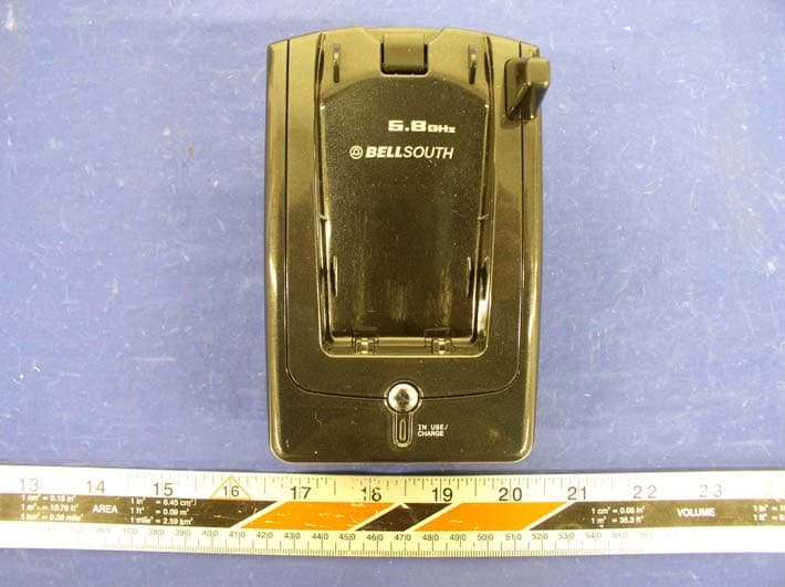
O63GH5815BALD04
Apr 15, 2004Analog Cordless Phone
Equipment Class
DXX - Part 15 Low Power Communication Device Transmitter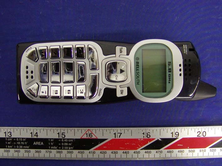
O63GH5815HALD04
Apr 15, 2004Analog Cordless Phone
Equipment Class
DXX - Part 15 Low Power Communication Device Transmitter
O63PM3320DLD04
Apr 05, 20042.4GHz Digital Spread-Spectrum Cordless Phone
Equipment Class
DTS - Digital Transmission System
O63PM3375DLD04
Mar 29, 20042.4GHz Digital Spread-Spectrum Cordless Phone
Equipment Class
DTS - Digital Transmission System