O63MH9110LD02900MHz Crdls Caller ID Phn w/ Call Waiting on H/S
Lionda Technology Co Ltd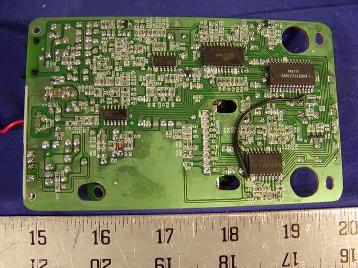
Click to zoom
Application Details
- Equipment Class
- DXT - Part 15 Low Power Transceiver, Rx Verified
- Date of Grant
- Mar 10, 2002
- Application Purpose
- Original Equipment
- Date of Application
- Mar 10, 2002
- Equipment Note
- 900MHz Crdls Caller ID Phn w/ Call Waiting on H/S
- Frequency Range
- 926.12000000 - 927.29000000
- Company
- Lionda Technology Co Ltd
- Country
- China
Documents & Files
Document Text
Text extracted from the exhibit documents filed with the FCC. Open a document above to read the original.
Users Manual
P AGE 900 MHz CORDLESS CALLER ID TELEPHONE WITH CALL WAITING 40 CHANNEL AUTOSCAN Model MH9110 PLEASE READ THIS MANUAL CAREFULLY BEFORE USE. KEEP FOR YOUR REFERENCE. OWNER'S MANUAL INSTALLATION AND OPERATING INSTRUCTIONS 5 © 1995, 2002 BellSouth Corporation TALK DIR SA VE RE DIAL ongratulations on your selection of a quality BellSouth Product. With proper care, and by following the setup and user instructions in this manual, this unit will provide you with years of trouble free service. BellSouth is committed to providing quality products that fit your needs. We would like to have any comments or suggestions you might have on this product. You may mail your comments to: U.S. Electronics 105 Madison Avenue New York, NY 10016 When examining your new BellSouth cordless telephone, you will find an array of special features including: Filtered Sound™ System - Receives considerably less noise than conventional cordless telephones because of a special circuit which delivers the clearest possible reception. 40 Channel Autoscan - Press the DEL/CHAN button on the HANDSET to find and lock on to the clearest channel for any call. Desk or Wall Mount - Use this equipment as a desk phone or as a wall phone. TONE or PULSE Dialing - Use this phone for either TONE (rotary) or PULSE (push- button) dialing. Automated Functions - Redial the last number called and automatic STANDBY mode. Security - Ensures greater privacy because a built-in security code with 65,536 combinations prevents use of your telephone line by another nearby cordless telephone. Dependable Battery - Recharge your BATTERY PACK many times with the built-in charger. The battery low warning tone tells you when the BATTERY PACK needs recharging (See page 27). Special Services - Use the EDIT/FLASH button to access special services such as Call Waiting supplied by your telephone company or company switchboard. STANDBY Mode - When in STANDBY mode (ON-HOOK), the telephone is capable of receiving a call. When the HANDSET is on the BASE UNIT, it is automatically in the STANDBY mode (ON-HOOK). When the HANDSET is taken off the BASE UNIT, it remains in the STANDBY mode until you activate the button. Battery Power Saver - Once fully charged, in STANDBY mode, the HANDSET can receive/send calls for a maximum of five days without the need for recharging. Length of charge depends on frequency of use. Luminous LCD Screen - The LCD Screen emits light for 10 seconds every time you press any of the TELEPHONE KEYPAD buttons. HANDSET Ringer Level - Select the ringer sound level (HI, LOW, OFF). HANDSET Volume Control Switch - Select the receiver volume level (HI, MID, LOW). C Special Features HEADSET JACK - Your telephone can utilize a headset for hands-free communication. BELT CLIP - Use the BELT CLIP to hang your HANDSET on your belt. CALLER ID SYSTEM Multi-Function Large LCD Screen - Shows the number you are dialing and, with Caller ID service (available through subscription from your local telephone company), displays information about the caller before you answer the call. Name and Number Directory - Stores up to 40 names and numbers so that you can call them with a single key stroke. Caller List - Available with Caller ID service. Stores up to 80 calls to keep track of everyone who called. The name, phone number, time and date of the call are recorded. Allows you to return their calls with a single key stroke. Preferred Calls - You can mark the name and number of a welcome caller in the DIRECTORY. When that number calls in, the caller’s name will appear on the DISPLAY and a special ring sound will be heard. Blocked Calls - You can mark the name and number of an unwelcome caller in the DIRECTORY. When that number calls in, the caller’s name will appear on the DISPLAY and the ringer will be disabled. Repeat Call Indicator - Shows if a new incoming call has called more than once. Unavailable Call Indicator - Advises you that the origin of the incoming call does not support the Caller ID system. Call Waiting Service - Displays the name and number of the second caller, if you have subscribed for Call Waiting service from your local telephone company (see page 13). Voice Mail - Indicates message waiting signal if you subscribed to Voice Mail message service and requested Visual Message Indication from your local telephone company (see page 13). This telephone also detects a Stutter Dial Tone signal every time there is a Voice Mail message for you from your Voice Mail message provider if you have subscribed to Voice Mail message service. Special Features TALK DIR SAVE R EDIAL 1. LARGE LCD SCREEN 11. DIR (DIRECTORY) BUTTON Pg. 14, 15, 16, 18, 19 15. DEL (DELETE)/CHAN (CHANNEL) BUTTON Pg. 9, 15, 16, 18, 19, 12. REDIAL/SAVE BUTTON Pg. 10, 15, 16, 18, 20~25 9. MESSAGE WAITING LED INDICATOR Pg. 13 NEW CALL/ 13. VOLUME CONTROL (HI, MID, LOW) SWITCH 10. BATT LOW INDICATOR Pg. 27 5. HEADSET JACK Pg. 11 4. MENU/VOICE MAIL BUTTON Pg. 13, 20~25 6. TELEPHONE KEYPAD Pg. 16~18, 20, 21, 24, 25 8. FLASH BUTTON Pg. 13, 14, 16, 18, 20~25 EDIT/ 16. CHARGE CONTACTS HANDSET Controls HANDSET Controls 1. items. 2. SCROLL UP-DOWN/SHIFT LEFT-RIGHT BUTTON Pg. 12, 14~16, 18~24 3. TALK BUTTON Pg. 6, 7, 9, 10, 13, 14, 18, 29 2. SCROLL UP -DOWN , SHIFT LEFT -RIGHT Button: 3. Button: Press to move around Press to answer an incoming call or to place a call. Press to end a call the large LCD Screen. Pg. 14, 19 7 14. OPTION BUTTON Pg. 9, 12 TALK HANDSET Controls 4. /VOICE MAIL Button: (MENU) Press to access the special functions operation in STANDBY mode. (For special functions see page 20~21.) (VOICE MAIL) Press to automatically dial the Voice Mail Post Code in your area to access your Voice Mail message. 5.HEADSET JACK: For connecting your headset plug to enjoy hands-free communication. (See page 11 for detail.) 6.TELEPHONE KEYPAD Buttons: Allows you to make a call depending on pressed button. (For TELEPHONE KEYPAD characters, see page 17.) 7.TEMPORARY TONE Button: Press to temporarily change t…
Text truncated - open the document above for the full version.
Block Diagram
9110bbd.sch-1 - Thu Feb 07 12:06:05 2002 9110hbd.sch-1 - Thu Feb 07 12:07:03 2002
External Photos
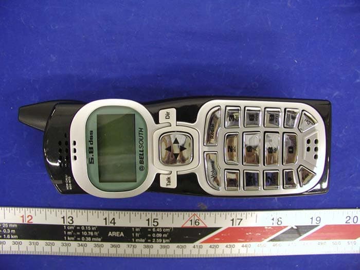
EUT EXTERNAL PHOTOGRAPHS Handset - Top View Handset - Bottom View Base - Top View Base - Bottom View
ID Label/Location Info
6 – FCC PRODUCT LABELING AND WARNING STATEMENT 6.1 FCC ID Label Specifications : Text is black or white in color and is left justified. Labels are silk- screened and shall be “permanently affixed” at a conspicuous location on the EUT. 6.2 Proposed Label Location on EUT Bottom Side of Base/Proposed FCC ID Label Location / Handset 6.3 FCC Warning Statement A FCC Warning Statement is provided in the product manual.
Internal Photos
EUT INTERNAL PHOTOGRAPHS Handset - Component View Handset - Solder View Handset - Transceiver Component View Handset - Transceiver Solder View 8.9 Base - Component View Base - Solder View Base - Transceiver Component View Base - Transmitter Solder View
Operational Description
LIONDA TECHNOLOGY COMPANY LIMITED ENGINEERING DEPARTMENT MH9110desc Page 1 2/22/2002 CIRCUIT DESCRIPTION Model: MH9110,MH9111 Base a. RF Transmitter Section – RF Board Compressed audio signal is frequency modulated through the varactor diode D3, D4. Diode D3, D4, L4 and Q5 the external components formed the voltage controlled oscillator circuit for the transmitter part. This circuit generates the TX VCO frequency. A portion of this signal is fed back to the PLL IC’s pin1 (FIN1) for phase comparison. Once the phase of oscillation stabilized, the PLL circuit generates the error voltage necessary for the VCO to oscillate at the desired transmitter’s RF frequency. The VCO circuit impedance is matched with the succeeding circuit through the transistor Q2 that also acts as the buffer amplifier. RF amplifier Q7 boosts the signal for transmission. This amplified RF signal is trimmed to the desired frequency band by BPF2403 so as not to interfere with the receiver circuit. The transmitter RF signal is then propagated through the antenna. b. RF Receiver Section - RF Board The Base Unit antenna receives RF signal. Band Pass Filter BPF903 trims the signal to the desirable frequency band. Transistor Q6 & Q3 is a low noise amplifier that boosts the RF signal to a specific level for mixing. PLL IC1 (KB8825B) is used as a Universal Phase Lock Loop circuit. The frequency from the Voltage Controlled Oscillator (VCO) D1, L5 and Q4, is fed back to the PLL IC through pin 16 (FIN2) for phase comparison. During channel scanning or turning the unit on, once the phase of oscillation stabilized (locked), the PLL circuit generates the first local oscillator frequency for down-converting the received RF signal into the first IF frequency 10.7MHz. This process is accomplished through the IF mixer circuit Q1. Q1 is used for matching the impedance of the mixer circuit with the succeeding circuits. The resulting IF signal is kept constant by the IF Filter FL1 to 10.7MHz which is then mixed with the second local oscillator frequency 11.150MHz (derived from X1 & C47) to produced a much lower IF frequency. This lower IF frequency if further filtered by IF Filter FL4 to produce a more stable signal of 450AKHz. Quadrature signal detection is accomplished internally by the Narrow-band Detector IC2 (KA3361) with the IF coil L7. The recovered audio frequency can be taken from IC2 audio output pin9. Double conversion of received signal is utilized to improve the image frequency rejection of the unit. c. Transmitter Audio Section – Main Board 1 LIONDA TECHNOLOGY COMPANY LIMITED ENGINEERING DEPARTMENT MH9110desc Page 2 2/22/2002 Audio Frequency signal from the telephone line is compressed through the compressor part of IC4 to minimize the transmission noise. The degree of compression depends on the external RC combinations. AGC is also utilized by IC4 to avoid shock noise caused by abrupt change of audio levels. The compressed audio is filtered and amplified for better acoustical performance. d. Receiver Audio Section – Main Board The compressed Audio Frequency signal is passed through passive RC filters for acoustic compliance. The filtered audio is then fed to the Compander IC4 for expansion thus retrieving the original Audio signal with noise filtered out. Q5 is used as buffer circuit. Bridge rectifier D12-D15 isolates the high-voltage telephone line to the rest of the circuit. D12-D15 is also act as a hybrid transformer to create a two-way path for audio transmission to and reception from the telephone line. Handset a. RF Transmitter Section – RF Board Refer to portion 1.b for this section. All circuit performance is the same except that Band Pass Filter BPF927 is changed to BPF903 for the handset transmission. b. RF Receiver Section – RF Board Refer to portion 1.b for this section. All circuit performance is the same except that Band Pass Filter BPF903 is changed to BPF927 for the handset reception. c. Transmitter Audio Section – Main Board Audio Frequency signal from the handset or from the headset microphone is compressed through the compressor part of IC1 to minimize the transmission noise. The degree of compression depends on the external RC combinations. AGC is also utilized by IC1 to avoid shock noise caused by abrupt change of audio levels. The compressed audio is filtered and amplified for better acoustical performance. Q3 is a switching transistor that controls the power supply for the TX RF part. d. Receiver Audio Section – Main Board The compressed Audio Frequency signal is passed through passive RC filters for acoustic compliance. The filtered audio is then fed to the Compander IC1 for expansion thus retrieving the original audio signal with noise filtered out. Q2 & Q10 act as audio amplifier to sufficiently drive the handset speaker. Q7 and Q8 are 2 2 LIONDA TECHNOLOGY COMPANY LIMITED ENGINEERING DEPARTMENT MH9110desc Page 3 2/22/2002 switching transistors that control the power supply for the RF part, the Compander part and the AF amplifier respectively. An earphone jack is provided for an optional headset unit for handsfree conversation on the handset. OTHERS (Handset): a. Charging and Reset Controls Recharging the handset battery is accomplished by putting the handset on the cradle. IC5 detects this action and sends a command to the CPU for proper exchange of security code. b. Ring Detection When the handset receives the ring command from the base unit, the CPU will send buzzer signal to the ringer amplifier Q5 and Q6 that drives the Buzzer. OTHERS (Base): a. Hook Switching and Dialing Hook switching and the transistor Q6 that is controlled by the CPU accomplishes pulse dialing. DTMF signal from the ladder circuit internal to the CPU is filtered and amplified by Q5. b. Over-voltage Protection Fuse1 and varistor Z1 act as high current and high voltage protectors for the telephone line interface. In case of presence of voltage surge across the telephone line, Fuse1 decreases its resistance and dumps the line vo…
Text truncated - open the document above for the full version.
Schematics
9110BM.SCH-1 - Thu Feb 07 12:00:38 2002 9110brf.sch-1 - Thu Feb 07 11:56:55 2002 9110HM.SCH-1 - Thu Feb 07 11:59:23 2002 9100hrf.sch-1 - Thu Feb 07 11:53:37 2002
Test Report
Note: This test report is specially limited to the above client company and the product model only. It may not be duplicated without prior written consent of Bay Area Compliance Laboratory Corporation. This report must not be used by the client to claim product endorsement by NVLAP or any agency of the U.S. Government. FCC PART 15 Subpart C EMI MEASUREMENT AND TEST REPORT For Lionda Technology Co., Ltd. Block 2 Laodong 2 nd Industrial Area, Xixiang, Baoan, Shenzhen, Guangdong, P.R.China 518102 FCC ID: O63MH9110LD02 January 22, 2002 This Report Concerns: Original Report Equipment Type: Cordless Telephone w/ CID and Call Waiting Test Engineer: Jeff Lee Test Date: January 15, 2001 Reviewed By: John Y. Chan – Engineering Manager Prepared By: Bay Area Compliance Laboratory Corporation 230 Commercial Street Sunnyvale, CA 94085 Tel (408) 732-9162 Fax (408) 732-9164 Lionda Technology Co., Ltd. FCC ID: O63MH9110LD02 Report # R0202044 Page 2 of 17 FCC Part 15 Subpart C Test Report TABLE OF CONTENTS 1 - GENERAL INFORMATION..................................................................................................................................3 1.1 PRODUCT DESCRIPTION FOR EQUIPMENT UNDER TEST (EUT) ..............................................................................3 1.2 OBJECTIVE.............................................................................................................................................................3 1.3 RELATED SUBMITTAL(S)/GRANT(S) ......................................................................................................................3 1.4 TEST METHODOLOGY............................................................................................................................................3 1.5 TEST FACILITY.......................................................................................................................................................3 1.6 TEST EQUIPMENT LIST...........................................................................................................................................4 1.8 LOCAL SUPPORT EQUIPMENT LIST AND DETAILS...................................................................................................4 1.9 EXTERNAL I/O CABLING LIST AND DETAILS.........................................................................................................4 2 - SYSTEM TEST CONFIGURATION.....................................................................................................................5 2.1 DESCRIPTION OF TEST CONFIGURATION................................................................................................................5 2.2 CONFIGURATION OF TEST SYSTEM (BASE)............................................................................................................6 2.3 TEST SETUP BLOCK DIAGRAM...............................................................................................................................6 2.4 EQUIPMENT MODIFICATIONS.................................................................................................................................6 3 - CONDUCTED EMISSIONS TEST DATA............................................................................................................7 3.1 MEASUREMENT UNCERTAINTY..............................................................................................................................7 3.2 EUT SETUP............................................................................................................................................................7 3.3 SPECTRUM ANALYZER SETUP................................................................................................................................7 3.4 TEST PROCEDURE..................................................................................................................................................8 3.5 SUMMARY OF TEST RESULTS.................................................................................................................................8 3.6 CONDUCTED EMISSIONS TEST DATA.....................................................................................................................8 3.7 PLOT OF CONDUCTED EMISSIONS TEST DATA.......................................................................................................8 4 - RADIATED EMISSION DATA ...........................................................................................................................10 4.1 MEASUREMENT UNCERTAINTY............................................................................................................................10 4.2 EUT SETUP..........................................................................................................................................................10 4.3 SPECTRUM ANALYZER SETUP..............................................................................................................................10 4.4 TEST PROCEDURE................................................................................................................................................11 4.5 CORRECTED AMPLITUDE & MARGIN CALCULATION...........................................................................................11 4.6 SUMMARY OF TEST RESULTS...............................................................................................................................12 4.7 RADIATED EMISSIONS TEST RESULT DATA.........................................................................................................13 5 - BAND EDGES TESTING .....................................................................................................................................16 5.1 TEST PROCEDURE................................................................................................................................................16 5.2 TEST EQUIPME…
Text truncated - open the document above for the full version.
Test Setup Photos
TEST SETUP PHOTOGRAPHS Base Conducted Emission - Front View Base Conducted Emission - Rear View Base Radiated Emission - Front View Base Radiated Emission Photograph – Rear View Handset Radiated Emission Photograph - Front View Handset Radiated Emission Photograph - Rear View
Contact Information
Applicant
Dan Coronia(Senior Engineer)
Test Firm
Bay Area Compliance LaboratoryJohn Chan
Technical Specifications
| # | Rule Parts | Frequency Range | Power Output |
|---|---|---|---|
| 2 | 15C | 926.12 MHz - 927.29 MHz | - |
Other Applications from Lionda Technology Co Ltd
O63GH5850HDLD03
May 23, 2004Digital Cordless Phone � Handset Unit
Equipment Class
DTS - Digital Transmission System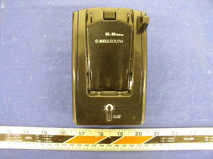
O63GH5815BALD04
Apr 15, 2004Analog Cordless Phone
Equipment Class
DXX - Part 15 Low Power Communication Device Transmitter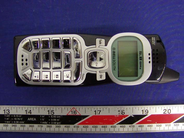
O63GH5815HALD04
Apr 15, 2004Analog Cordless Phone
Equipment Class
DXX - Part 15 Low Power Communication Device Transmitter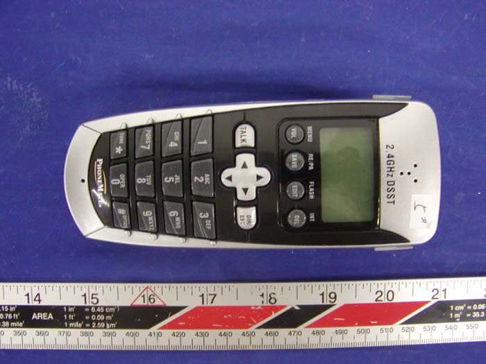
O63PM3320DLD04
Apr 05, 20042.4GHz Digital Spread-Spectrum Cordless Phone
Equipment Class
DTS - Digital Transmission System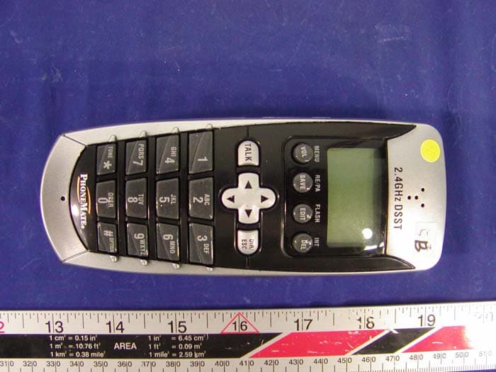
O63PM3375DLD04
Mar 29, 20042.4GHz Digital Spread-Spectrum Cordless Phone
Equipment Class
DTS - Digital Transmission System