O63XG2400ALD032.4 GHz 50 Ch Analog Cordless Telephone
Lionda Technology Co Ltd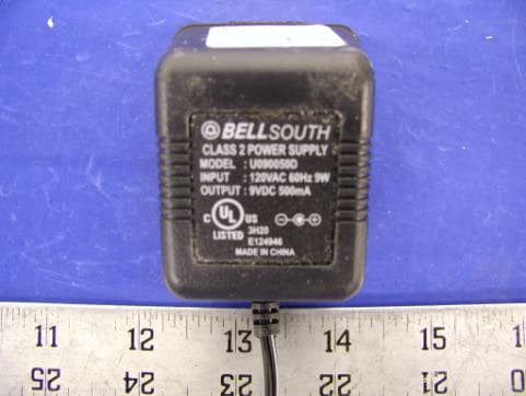
Click to zoom
Application Details
- Equipment Class
- DXX - Part 15 Low Power Communication Device Transmitter
- Date of Grant
- Mar 09, 2003
- Application Purpose
- Original Equipment
- Date of Application
- Mar 09, 2003
- Equipment Note
- 2.4 GHz 50 Ch Analog Cordless Telephone
- Frequency Range
- 2472.21500000 - 2476.93900000
- Company
- Lionda Technology Co Ltd
- Country
- China
Documents & Files
Document Text
Text extracted from the exhibit documents filed with the FCC. Open a document above to read the original.
Users Manual
2.4 GHz CORDLESS ALL DIGITAL ANSWERING SYSTEM WITH CALLER ID/CALL WAITING 50 CHANNEL AUTOSCAN WITH 4 INDIVIDUAL MAILBOXES Model XG2400 OWNER'S MANUAL INSTALLATION AND OPERATING INSTRUCTIONS PLEASE READ THIS MANUAL CAREFULLY BEFORE USE. KEEP FOR YOUR REFERENCE. on page 7 or your separate Quick Start guide. Visit Us on the Web: www.uselectronics.info Special Features ongratulations on your selection of a quality XACT Product. With proper care and adherence to the setup and user instructions in this Owner’s Manual, this unit will provide you with years of trouble free service. BellSouth is committed to providing quality products that fit your needs. We would like to have any comments or suggestions you might have on this product. You may mail your comments to: U.S. Electronics 105 Madison Avenue New York, NY 10016 When examining your new XACT cordless telephone, you will find an array of special features including: Filtered Sound™ System - Receives considerably less noise than conventional cordless telephones because of a special circuit which delivers the clearest possible reception. 50 Channel Autoscan - Press the button on the HANDSET to find and lock on to the clearest channel for any call. Desk or Wall Mount - Use this equipment as a desk phone or as a wall phone. TONE or PULSE Dialing - Use this phone for either TONE (push-button) or PULSE (rotary) dialing. Automated Functions - Redial the last number called and automatic STANDBY mode. Security - Ensures greater privacy because a built-in security code with 65,536 combinations prevents use of your telephone line by another nearby cordless telephone. Dependable Battery - Recharge your BATTERY PACK many times with the built-in charger. The battery low warning tone tells you when the BATTERY PACK needs recharging (See page 37). Special Services - Use the button to access special services such as Call Waiting supplied by your telephone company or company switchboard. STANDBY Mode - When in STANDBY mode (ON-HOOK), the telephone is capable of receiving a call. When the HANDSET is on the BASE UNIT, it is automatically in the STANDBY mode (ON-HOOK). When the HANDSET is taken off the BASE UNIT, it remains in the STANDBY mode until you activate the button. Battery Power Saver - Once fully charged, in STANDBY mode, the HANDSET can receive/send calls for a maximum of five days without the need for recharging. Length of charge depends on frequency of use. HANDSET Ringer Level - Select the ringer sound level (HI, LOW, OFF). HANDSET Volume Control Switch - Select the receiver volume level (HI, MID, LOW). Luminous LCD Screen - The LCD Screen emits light for 10 seconds every time you press any of the TELEPHONE KEYPAD buttons. HEADSET JACK - Your telephone can utilize a headset for hands-free communication. BELT CLIP - Use the BELT CLIP to hang your HANDSET on your belt. C DEL/CHAN EDIT/FLASH TALK Special Features CALLER ID SYSTEM Multi-Function Large LCD Screen - Shows the number you are dialing, and with Caller ID service (available through subscription from your local telephone company), displays information about the caller before you answer the call. Name and Number DIRECTORY (PHONE BOOK) - Stores up to 40 names and numbers so that you can call them with a single key stroke. Caller List - Available with Caller ID service. Stores up to 80 calls to keep track of everyone who called. The name, phone number, time, and date of the call are recorded. Allows you to return their calls with a few key strokes. Preferred Calls - You can mark the name and number of a welcome caller in the DIRECTORY (PHONE BOOK). When that number calls in, the caller’s name will appear on the LCD Screen and a special ring sound will be heard. Blocked Calls - You can mark the name and number of an unwelcome caller in the DIRECTORY (PHONE BOOK). When that number calls in, the caller’s name will appear on the LCD Screen and the ringer will be disabled. Repeat Call Indicator - Shows if a new incoming call has called more than once. Unavailable Call Indicator - Advises you that the origin of the incoming call does not support the Caller ID system. Call Waiting Service - Displays the name and number of the second caller, if you have subscribed for Call Waiting service from your local telephone company (see page 15). Voice Mail - Indicates message waiting signal if you subscribed to Voice Mail message service and requested Visual Message Indication from your local telephone company (see page 15). ANSWERING SYSTEM FEATURES Fully Digital Answering System - Provides a full range of answering functions without using cassette tapes. Digital Memory - Allows recording of memos and messages. Two-Digit LED Message Display - Indicates the number of messages, indicates the status of the system. Ring-Detection Selectable - Choose the number of times the telephone rings before the system answers. Voice Day/Time Stamp - System tells the day and time of each received message or recorded memo. Message Alert - The ability to generate a sound signal when new messages are recorded. Call Screening - The ability to intercept a call when the unit is recording an incoming message (ICM). Mailboxes - Allows four separate individuals to receive their own incoming messages. Auto Disconnection - Will automatically stop answering when the HANDSET of any phone on the same line goes OFF-HOOK. Fast Message Skip Function - Skips to the next message. HANDSET Controls 3. NEW CALL/MSG WTG (MESSAGE WAITING) LED Indicator: (NEW CALL) Blinks in RED color to indicate that you have a new Caller ID call stored in memory. (MESSAGE WAITING) Blinks in GREEN color when receiving a Message Waiting signal, if you have subscribed to a Voice Mail message service from your local telephone company (See page 15.) HANDSET Controls 1. Large LCD Screen: Shows call information, phone status, prompts, and DIRECTORY (PHONE BOOK) items. large LCD Screen. 1. LARGE LCD SCREEN 10. DIR (DIRECTORY) BUTTON Pg. 16~21 16. DEL (DELETE)/CHAN (CHANNEL) …
Text truncated - open the document above for the full version.
Cover Letter(s)
Block 2 Laodong 2nd Industria Area, Xixian, Baoan, Shenzhen, China Tel.: 86-755-7917824/ 86-755-7902415, Fax: 86-755-7917944 Federal Communications Commission Authorization and Evaluation Division Confidentiality Request regarding application for certification of FCC ID: O63XG2400ALD03. Pursuant to Sections 0.457 and 0.459 of the Commission’s Rules, we hereby request confidential treatment of information accompanying this application as outlined below: • Schematics • Block Diagram • Circuit Description The above documents contain information for new 2.4 GHz DSS (Cordless Telephone) technology and ideas, so we would like to prevent the use of this information by other companies. The applicant understands that pursuant to Section 0.457 of the Rules, disclosure of this application and all accompanying documentation will not be made before the date of the Grant for this application. Sincerely, Dan Coronia – Senior Engineer
External Photos
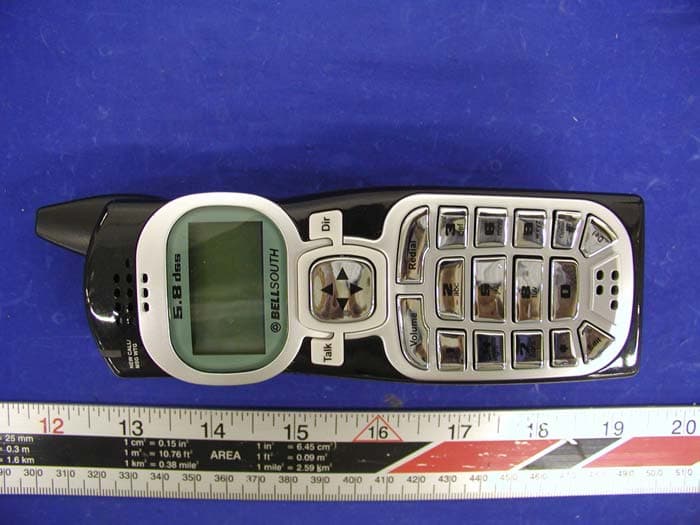
APPENDIX C - EUT EXTERNAL PHOTOGRAPHS Handset - Top View Handset - Bottom View Base - Top View Base - Bottom View AC Adapter – Top View
ID Label/Location Info
APPENDIX A - FCC PRODUCT LABELING AND WARNING STATEMENT FCC ID Label 1.0” 2.1875” Specifications: Text is black or white in color and is left justified. Labels are silk- screened and shall be “permanently affixed” at a conspicuous location on the EUT. Proposed Label Location on EUT Port Side of EUT Base/Proposed FCC ID Label Location / EUT Handset FCC Warning Statement A FCC Warning Statement is provided in the product manual. FCC ID: O63XG2400ALD03 This device complies with Part 15 of the FCC Rules. Operation is subject to the following two conditions: (1) this device may not cause harmful interference, and (2) this device must accept any interference received, including interference that ma cause undesired operation. (2) Privacy of communications may not be ensured when using this phone.
Internal Photos
APPENDIX C - EUT INTERNAL PHOTOGRAPHS Handset - LCD View Handset - Cover Off View Handset – Transmitter Component View Handset – Transmitter Solder View Base – Uncover View Base – Main Board Component View (1) Base – Main Board Solder View (1) Base – Main Board Component View (2) Base – Main Board Solder View (2) Base – Transmitter Component View (1) Base – Transmitter Component View (2) Base – Transmitter Solder View
Test Report
Note: This test report is specially limited to the above client company and the product model only. It may not be duplicated without prior written consent of Bay Area Compliance Laboratory Corporation. This report must not be used by the client to claim product endorsement by NVLAP or any agency of the U.S. Government. FCC PART 15 Subpart C EMI MEASUREMENT AND TEST REPORT For Lionda Technology Co., Ltd. Block 2 Laodong 2 nd Industrial Area, Xixiang, Baoan, Shenzhen, Guangdong, P.R.China 518102 FCC ID: O63XG2400ALD03 February 22, 2003 This Report Concerns: Original Report Equipment Type: 2.4GH Cordless Telephone Test Engineer: Ming Jing Report No.: R0302035 Test Date: January 30, 2003 Reviewed By: Prepared By: Bay Area Compliance Laboratory Corporation 230 Commercial Street Sunnyvale, CA 94085 Tel (408) 732-9162 Fax (408) 732-9164 Lionda Technology Co., Ltd. FCC ID: O63XG2400ALD03 Report # R0302035.doc Page 2 of 17 FCC Part 15 Subpart C Test Report TABLE OF CONTENTS 1 - GENERAL INFORMATION.................................................................................................................................................3 1.1 PRODUCT DESCRIPTION FOR EQUIPMENT UNDER TEST (EUT)........................................................................................3 1.2 OBJECTIVE................................................................................................................................................................................3 1.3 RELATED SUBMITTAL(S)/GRANT(S)....................................................................................................................................3 1.4 TEST METHODOLOGY.............................................................................................................................................................3 1.5 TEST FACILITY.........................................................................................................................................................................4 1.6 TEST EQUIPMENT LIST............................................................................................................................................................4 1.8 LOCAL SUPPORT EQUIPMENT LIST AND DETAILS..............................................................................................................5 1.9 EXTERNAL I/O CABLING LIST AND DETAILS......................................................................................................................5 2 - SYSTEM TEST CONFIGURATION...................................................................................................................................6 2.1 DESCRIPTION OF TEST CONFIGURATION..............................................................................................................................6 2.2 CONFIGURATION OF TEST SYSTEM (BASE).........................................................................................................................7 2.3 TEST SETUP BLOCK DIAGRAM..............................................................................................................................................7 2.4 EQUIPMENT MODIFICATIONS.................................................................................................................................................7 3 - CONDUCTED EMISSIONS TEST DATA.........................................................................................................................8 3.1 MEASUREMENT UNCERTAINTY.............................................................................................................................................8 3.2 EUT SETUP...............................................................................................................................................................................8 3.3 SPECTRUM ANALYZER SETUP...............................................................................................................................................8 3.4 TEST PROCEDURE....................................................................................................................................................................8 3.5 SUMMARY OF TEST RESULTS.................................................................................................................................................9 3.6 CONDUCTED EMISSIONS TEST DATA....................................................................................................................................9 3.7 PLOT OF CONDUCTED EMISSIONS TEST DATA....................................................................................................................9 4 - RADIATED EMISSION DATA..........................................................................................................................................12 4.1 MEASUREMENT UNCERTAINTY...........................................................................................................................................12 4.2 EUT SETUP.............................................................................................................................................................................12 4.3 SPECTRUM ANALYZER SETUP.............................................................................................................................................12 4.4 TEST PROCEDURE..................................................................................................................................................................13 4.5 CORRECTED AMPLITUDE & MARGIN CALCULATION......................................................................................................13 4.6 SUMMARY OF TEST RESULTS...............................................................................................................................................13 4.7 RADIATED EMISSIONS TEST RESULT DATA....................................…
Text truncated - open the document above for the full version.
Test Report
APPENDIX B - TEST SETUP PHOTOGRAPHS Base Conducted Emission - Front View Base Conducted Emission - Rear View Base Radiated Emission - Front View Base Radiated Emission - Rear View Handset Radiated Emission - Front View Handset Radiated Emission - Rear View
Test Report
4 - RADIATED EMISSION DATA 4.1 Measurement Uncertainty All measurements involve certain levels of uncertainties, especially in field of EMC. The factors contributing to uncertainties are spectrum analyzer, cable loss, antenna factor calibration, antenna directivity, antenna factor variation with height, antenna phase center variation, antenna factor frequency interpolation, measurement distance variation, site imperfections, mismatch (Average), and system repeatability. Based on NIS 81, The Treatment of Uncertainty in EMC Measurements, the best estimate of the uncertainty of a radiation emissions measurement at BACL is + 4.0 dB. 4.2 EUT Setup The radiated emission tests were performed in the open area 3-meter test site, using the setup in accordance with the ANSI C63.4 - 1992. The specification used was the FCC 15 Subpart C limits. The Base of EUT was connected to a 110 VAC / 60 Hz power source. The spacing between the peripherals was 10 centimeters. The external Input / Output cables were draped over edge of the test table and bundle when necessary. 4.3 Spectrum Analyzer Setup According to FCC Rules, 47 CFR 15.33 (a) (1), the system was tested to 25GHz. During the radiated emission test, the spectrum analyzer was set with the following configurations: Start Frequency ........................................................... 30 MHz Stop Frequency ........................................................... 25GHz Sweep Speed ............................................................... Auto IF Bandwidth .............................................................. 1 MHz Video Bandwidth ........................................................ 1 MHz Quasi-Peak Adapter Bandwidth.................................. 120 kHz Quasi-Peak Adapter Mode .......................................... Normal Resolution Bandwidth................................................. 1MHz 4.4 Test Procedure For the radiated emissions test, both the EUT and all support equipment power cords were connected to the AC floor outlet since the power supply (U090050D) used in the EUT did not provide an accessory power outlet. Maximizing procedure was performed on the six (6) highest emissions to ensure EUT complianceis with all installation combinations. All data was recorded in the Peak detection mode. Quasi-Peak readings was performed only when an emission was found to be marginal (within -4 dB of specification limit), and are distinguished with a "Qp" in the data table . 4.5 Corrected Amplitude & Margin Calculation The Corrected Amplitude is calculated by adding the Antenna Factor and Cable Factor, and subtracting the Amplifier Gain from the Amplitude reading. The basic equation is as follows: Corr. Ampl. = Indicated Reading + Antenna Factor + Cable Factor - Amplifier Gain The “Margin” column of the following data tables indicates the degree of compliance with the applicable limit. For example, a margin of -7dBμV means the emission is 7dBμV below the maximum limit for Class B. The equation for margin calculation is as follows: Margin = Corr. Ampl. - Class B Limit 4.6 Summary of Test Results According to the data in section 4.7, the EUT complied with the FCC Title 47, Part 15, Subpart C, section 15.205, 15.207, and 15.249 after tested to 10 th harmonics as required by FCC and had the worst margin of: For Handset: -9.9 dBμV at 4944.43 MHz in the Horizontal polarization at Low Frequency, 30 to 25GHz, 3 meters -7.8 dBμV at 4953.88 MHz in the Vertical polarization at High Frequency, 30 to 25GHz, 3 meters Handset Unit, Intentional Emission, 30 MHz to 25GHz, 3 meters INDICATED TABLE ANTENNA CORRECTION FACTOR CORRECTED AMPLITUDE FCC 15 SUBPART C Frequency Ampl. Angle Height Polar Antenna Cable Amp. Corr. Ampl. Limit Margin MHz dBμV/m Comments Degree Meter H/ V dBμV/m DB dB dBμV/m dBμV/m dB Low Frequency 82.12 48.7 / 0 1.2 V 9.5 1.2 25.0 34.4 40.0 -5.6 930.02 37.3 / 270 2.0 H 23.6 4.1 25.0 40.0 46.0 -6.0 66.78 48.1 / 30 1.2 V 9.3 1.2 25.0 33.6 40.0 -6.4 550.00 42.3 / 120 2.0 H 19.3 2.8 25.0 39.4 46.0 -6.6 4944.43 36.7 AVE 180 1.8 H 32.5 4.9 30.0 44.1 54.0 -9.9 111.90 45.2 / 90 2.0 H 11.3 1.5 25.0 33.0 43.5 -10.5 2472.22 77.8 AVE 330 1.5 V 28.1 3.4 30.0 79.3 94.0 -14.7 4944.43 30.2 AVE 30 1.8 V 32.5 4.9 30.0 37.6 54.0 -16.4 2472.22 72.7 AVE 270 1.5 H 28.1 3.4 30.0 74.1 94.0 -19.9 4944.43 45.5 PEAK 180 1.8 H 32.5 4.9 30.0 52.9 74.0 -21.1 4944.43 42.5 PEAK 30 1.8 V 32.5 4.9 30.0 49.9 74.0 -24.1 2472.22 82.0 PEAK 330 1.5 V 28.1 3.4 30.0 83.5 114.0 -30.6 2472.22 79.3 PEAK 270 1.5 H 28.1 3.4 30.0 80.8 114.0 -33.2 High Frequency 70.02 48.2 / 30 1.2 V 9.2 1.2 25.0 33.6 40.0 -6.4 4953.88 38.8 AVE 270 1.2 V 32.5 4.9 30.0 46.2 54.0 -7.8 959.02 34.2 PEAK 300 2.0 H 23.3 4.3 25.0 36.8 46.0 -9.2 420.90 40.8 PEAK 270 2.5 H 16.5 2.7 25.0 35.0 46.0 -11.0 4953.88 34.8 AVE 270 2.0 H 32.5 4.9 30.0 42.2 54.0 -11.8 150.00 40.9 / 90 2.0 V 12.7 1.7 25.0 30.3 43.5 -13.2 257.08 40.6 / 90 1.2 V 13.3 2.2 25.0 31.1 46.0 -14.9 4953.88 47.3 PEAK 270 2.0 H 32.5 4.9 30.0 54.7 74.0 -19.3 4953.88 46.1 PEAK 270 1.2 V 32.5 4.9 30.0 53.5 74.0 -20.5 2476.94 71.2 AVE 120 1.0 H 28.1 3.4 30.0 72.6 94.0 -21.4 2476.94 64.8 AVE 90 1.5 V 28.1 3.4 30.0 66.3 94.0 -27.8 2476.94 74.0 PEAK 120 1.0 H 28.1 3.4 30.0 75.5 114.0 -38.6 2476.94 71.9 PEAK 90 1.5 V 28.1 3.4 30.0 73.4 114.0 -40.7 FUND: Fundamental Handset Radiated Emission Front View Handset Radiated Emission Rear View
Test Report
4 - RADIATED EMISSION DATA 4.1 Measurement Uncertainty All measurements involve certain levels of uncertainties, especially in field of EMC. The factors contributing to uncertainties are spectrum analyzer, cable loss, antenna factor calibration, antenna directivity, antenna factor variation with height, antenna phase center variation, antenna factor frequency interpolation, measurement distance variation, site imperfections, mismatch (Average), and system repeatability. Based on NIS 81, The Treatment of Uncertainty in EMC Measurements, the best estimate of the uncertainty of a radiation emissions measurement at BACL is + 4.0 dB. 4.2 EUT Setup The radiated emission tests were performed in the open area 3-meter test site, using the setup in accordance with the ANSI C63.4 - 1992. The specification used was the FCC 15 Subpart C limits. The Base of EUT was connected to a 110 VAC / 60 Hz power source. The spacing between the peripherals was 10 centimeters. The external Input / Output cables were draped over edge of the test table and bundle when necessary. 4.3 Spectrum Analyzer Setup According to FCC Rules, 47 CFR 15.33 (a) (1), the system was tested to 25GHz. During the radiated emission test, the spectrum analyzer was set with the following configurations: Start Frequency ........................................................... 30 MHz Stop Frequency ........................................................... 25GHz Sweep Speed ............................................................... Auto IF Bandwidth .............................................................. 1 MHz Video Bandwidth ........................................................ 1 MHz Quasi-Peak Adapter Bandwidth.................................. 120 kHz Quasi-Peak Adapter Mode .......................................... Normal Resolution Bandwidth................................................. 1MHz 4.4 Test Procedure For the radiated emissions test, both the EUT and all support equipment power cords were connected to the AC floor outlet since the power supply (U090050D) used in the EUT did not provide an accessory power outlet. Maximizing procedure was performed on the six (6) highest emissions to ensure EUT complianceis with all installation combinations. All data was recorded in the Peak detection mode. Quasi-Peak readings was performed only when an emission was found to be marginal (within -4 dB of specification limit), and are distinguished with a "Qp" in the data table . 4.5 Corrected Amplitude & Margin Calculation The Corrected Amplitude is calculated by adding the Antenna Factor and Cable Factor, and subtracting the Amplifier Gain from the Amplitude reading. The basic equation is as follows: Corr. Ampl. = Indicated Reading + Antenna Factor + Cable Factor - Amplifier Gain The “Margin” column of the following data tables indicates the degree of compliance with the applicable limit. For example, a margin of -7dBμV means the emission is 7dBμV below the maximum limit for Class B. The equation for margin calculation is as follows: Margin = Corr. Ampl. - Class B Limit 4.6 Summary of Test Results According to the data in section 4.7, the EUT complied with the FCC Title 47, Part 15, Subpart C, section 15.205, 15.207, and 15.249 after tested to 10 th harmonics as required by FCC and had the worst margin of: For Handset: -9.9 dBμV at 4944.43 MHz in the Horizontal polarization at Low Frequency, 30 to 25GHz, 3 meters -7.8 dBμV at 4953.88 MHz in the Vertical polarization at High Frequency, 30 to 25GHz, 3 meters Handset Unit, Intentional Emission, 30 MHz to 25GHz, 3 meters INDICATED TABLE ANTENNA CORRECTION FACTOR CORRECTED AMPLITUDE FCC 15 SUBPART C Frequency Ampl. Angle Height Polar Antenna Cable Amp. Corr. Ampl. Limit Margin MHz dBμV/m Comments Degree Meter H/ V dBμV/m DB dB dBμV/m dBμV/m dB Low Frequency 82.12 48.7 / 0 1.2 V 9.5 1.2 25.0 34.4 40.0 -5.6 930.02 37.3 / 270 2.0 H 23.6 4.1 25.0 40.0 46.0 -6.0 66.78 48.1 / 30 1.2 V 9.3 1.2 25.0 33.6 40.0 -6.4 550.00 42.3 / 120 2.0 H 19.3 2.8 25.0 39.4 46.0 -6.6 4944.43 36.7 AVE 180 1.8 H 32.5 4.9 30.0 44.1 54.0 -9.9 111.90 45.2 / 90 2.0 H 11.3 1.5 25.0 33.0 43.5 -10.5 2472.22 77.8 AVE 330 1.5 V 28.1 3.4 30.0 79.3 94.0 -14.7 4944.43 30.2 AVE 30 1.8 V 32.5 4.9 30.0 37.6 54.0 -16.4 2472.22 72.7 AVE 270 1.5 H 28.1 3.4 30.0 74.1 94.0 -19.9 4944.43 45.5 PEAK 180 1.8 H 32.5 4.9 30.0 52.9 74.0 -21.1 4944.43 42.5 PEAK 30 1.8 V 32.5 4.9 30.0 49.9 74.0 -24.1 2472.22 82.0 PEAK 330 1.5 V 28.1 3.4 30.0 83.5 114.0 -30.6 2472.22 79.3 PEAK 270 1.5 H 28.1 3.4 30.0 80.8 114.0 -33.2 High Frequency 70.02 48.2 / 30 1.2 V 9.2 1.2 25.0 33.6 40.0 -6.4 4953.88 38.8 AVE 270 1.2 V 32.5 4.9 30.0 46.2 54.0 -7.8 959.02 34.2 PEAK 300 2.0 H 23.3 4.3 25.0 36.8 46.0 -9.2 420.90 40.8 PEAK 270 2.5 H 16.5 2.7 25.0 35.0 46.0 -11.0 4953.88 34.8 AVE 270 2.0 H 32.5 4.9 30.0 42.2 54.0 -11.8 150.00 40.9 / 90 2.0 V 12.7 1.7 25.0 30.3 43.5 -13.2 257.08 40.6 / 90 1.2 V 13.3 2.2 25.0 31.1 46.0 -14.9 4953.88 47.3 PEAK 270 2.0 H 32.5 4.9 30.0 54.7 74.0 -19.3 4953.88 46.1 PEAK 270 1.2 V 32.5 4.9 30.0 53.5 74.0 -20.5 2476.94 71.2 AVE 120 1.0 H 28.1 3.4 30.0 72.6 94.0 -21.4 2476.94 64.8 AVE 90 1.5 V 28.1 3.4 30.0 66.3 94.0 -27.8 2476.94 74.0 PEAK 120 1.0 H 28.1 3.4 30.0 75.5 114.0 -38.6 2476.94 71.9 PEAK 90 1.5 V 28.1 3.4 30.0 73.4 114.0 -40.7 FUND: Fundamental Handset Radiated Emission Front View Handset Radiated Emission Rear View
Test Setup Photos
APPENDIX B - TEST SETUP PHOTOGRAPHS Base Conducted Emission - Front View Base Conducted Emission - Rear View Base Radiated Emission - Front View Base Radiated Emission - Rear View Handset Radiated Emission - Front View Handset Radiated Emission - Rear View
Contact Information
Applicant
Dan Coronia(Senior Engineer)
Test Firm
Bay Area Compliance LaboratoryJohn Chan
Technical Specifications
| # | Rule Parts | Frequency Range | Power Output |
|---|---|---|---|
| 2 | 15C | 2.47 GHz - 2.48 GHz | - |
Other Applications from Lionda Technology Co Ltd
O63GH5850HDLD03
May 23, 2004Digital Cordless Phone � Handset Unit
Equipment Class
DTS - Digital Transmission System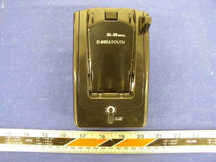
O63GH5815BALD04
Apr 15, 2004Analog Cordless Phone
Equipment Class
DXX - Part 15 Low Power Communication Device Transmitter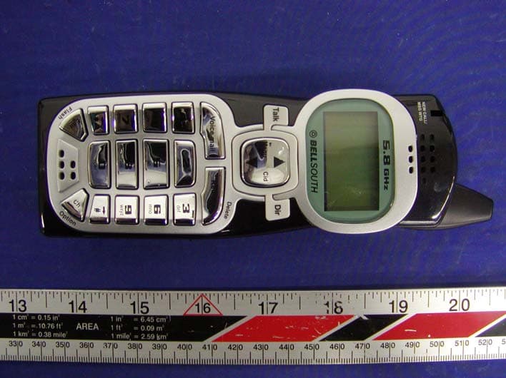
O63GH5815HALD04
Apr 15, 2004Analog Cordless Phone
Equipment Class
DXX - Part 15 Low Power Communication Device Transmitter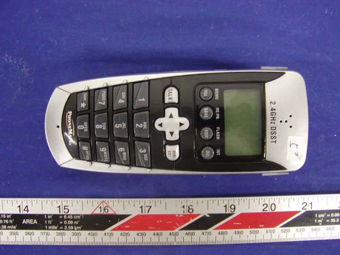
O63PM3320DLD04
Apr 05, 20042.4GHz Digital Spread-Spectrum Cordless Phone
Equipment Class
DTS - Digital Transmission System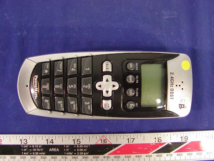
O63PM3375DLD04
Mar 29, 20042.4GHz Digital Spread-Spectrum Cordless Phone
Equipment Class
DTS - Digital Transmission System