O63XG2601DLD032.4 GHz 77 Channels Cordless Phone
Lionda Technology Co Ltd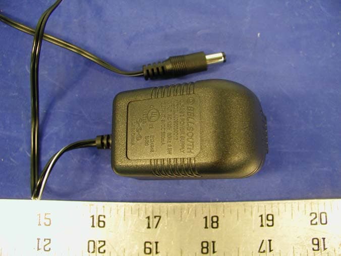
Click to zoom
Application Details
- Equipment Class
- DTS - Digital Transmission System
- Date of Grant
- Mar 31, 2003
- Application Purpose
- Original Equipment
- Date of Application
- Mar 31, 2003
- Equipment Note
- 2.4 GHz 77 Channels Cordless Phone
- Frequency Range
- 2402.30000000 - 2480.13000000
- Company
- Lionda Technology Co Ltd
- Country
- China
Documents & Files
Document Text
Text extracted from the exhibit documents filed with the FCC. Open a document above to read the original.
Users Manual
DSST~2601.qxd 3/8/2003 11:47 AM Page 1 Special FeaturesSpecial Features ongratulations on your selection of a quality XACT Product. With proper care and adherence to the set-up and user instructions in this Owner's Manual, this unit will provide you with years of trouble-free service. XACTis committed to providing quality products that fit your needs. We would like to have any comments or suggestions you might have on this product. You may mail your comments to: XACT 105 Madison Avenue New York, NY 10016 When examining your new XACT cordless telephone, you will find an array of special features including: Digital Spread Spectrum Technology - Utilizes a “wider frequency band” for a more secure conversation with a clarity of digital sound, extended range, and minimal interference from other cordless telephones. 77 Channel Auto-hop- When interference is received, the telephone automatically hops to the clearest channel. Desk or Wall Mount- Use this equipment as a desk phone or as a wall phone. Tone or Pulse Dialing- Use this phone for either TONE (push-button) or PULSE (rotary) dialing. Automated Functions - Redial the last number called and automatic STANDBY mode. Security- Ensures greater privacy because of a built-in security code with 4,000,000 possible combinations that prevents use of your telephone line by another nearby cordless phone. Special Services- Use the button to access special services such as Call Waiting supplied by your telephone company or company switchboard. STANDBY Mode- When in STANDBY mode (ON-HOOK), the phone is capable of receiving a call. When the HANDSETis on the BASE UNIT, it is automatically in the STANDBY mode (ON- HOOK). When the HANDSETis taken off the BASE UNIT, it remains in the STANDBY mode until you activate the button. Battery Power Saver- Recharge your BATTERYPACK many times with the built-in CHARGER. Once fully charged, in STANDBY mode, the HANDSET can receive/send calls for a maximum of ten days without the need for recharging. Length of charge depends on frequency of use. Luminous LCD Screen- The LCD Screen emits light for 5 seconds everytime you press any of the TELEPHONE KEYPAD buttons. HANDSET Ringer Level- Select the ringer sound level (High, Low, Off). HANDSET Ringer Melody- Select the desired ringer melody from the 10 available melodies. HANDSET Volume Control- Press the /MENU buttonand thenselect the desired receiver volume setting from Low, Medium, High, or Maximum. Alarm Clock- The telephone emits a distinctive sound when the ALARM CLOCK function is activated (See page 26). HEADSET JACK- Your telephone can utilize a headset for hands-free communication. BELT CLIP- Use the BELTCLIP to hang your HANDSET on your belt. EDIT/FLASH TALK C VOL DSST~2601.qxd 3/8/2003 11:47 AM Page 2 Special Features CALLER ID SYSTEM Multi-Function Large LCD Screen- Shows the number you are dialing and, with Caller ID service (available through subscription from your local telephone company), displays information about the caller before you answer the call. Name and Number DIRECTORY (PHONE BOOK) - Stores up to 40 names and numbers so that you can call them with a single key stroke. Caller List- Available with Caller ID service. Stores up to 50 calls to keep track of everyone you called. The name, phone number, time and date of the call are recorded. Allows you to return their calls with a few key strokes. Outgoing Call Memory- The telephone stores the last 8 OUTGOING CALLS to keep track of the one you called. The phone number, time, date, and the duration of the call are recorded. Allows you to call them again with a single key stroke. Preferred Calls - You can mark the name and number of a welcome caller in the DIRECTORY (PHONE BOOK). When that number calls in, the caller’s name will appear on the LCD Screen and a special ring will sound or a selected PREFERRED RING MELODY will be heard. Blocked Calls - You can mark the name and number of an unwelcome caller in the DIRECTORY (PHONE BOOK). When that number calls in, the caller’s name will appear on the LCD Screen and the ringer will be disabled. Repeat Call Indicator- Shows if a new incoming call has called more than once. Out of Area Call Indicator- Advises you that the incoming call is not in a Caller ID service area. Unavailable Call Indicator- Advises you that the origin of the incoming call does not support the Caller ID system. Call Waiting Service- Displays the name and number of the second caller, if you have subscribed to Call Waiting service from your local telephone company (see page 13.) MULTI-HANDSET, MULTI-BASE UNIT SYSTEM Multi-HANDSET- Registers a total of 9 HANDSETSinto the operating system. Multi-BASEUNIT -The user can have the option to add another BASEUNIT. The system supports 2 BASEUNITSconnected to separate telephone lines. Once registered, the HANDSETScan link to either of the BASE UNITSto make and/or receive a call. Automatic Linking - All 9 HANDSETS can register to the twoBASE UNITS (B1, B2). When the FIRST BASEUNIT (B1)is already engaged, the other HANDSETScan automatically link to the SECOND BASEUNIT (B2)by pressing the button. Intercom Call- A HANDSETcan make an INTERCOM call to the other HANDSETS in the system. Call Transfer- During a telephone conversation, the call can be transferred from one HANDSETto another HANDSET. Extension Phone Detection- When one HANDSETis connected to a BASEUNIT, the LCD Screen of the other HANDSETSthat are linked to the same BASEUNITwill display “Ext in-use.” TALK DSST~2601.qxd 3/8/2003 11:47 AM Page 3 HANDSET ControlsHANDSET Controls DSST~2601.qxd 3/8/2003 11:47 AM Page 4 HANDSET Controls 4./MENUButton:(VOLUME) During TALK mode, press to adjust the receiver volume to a comfortable listening level. (MENU) Press to accessthe special functions operation in STANDBY mode. (For special functions see pages 20~26.) 5.HEADSET JACK:For connecting your headset plug to enjoy hands-free communication. (See page 11 for detail.) 6.TELEPHONE KEYPAD to Buttons: Allows you …
Text truncated - open the document above for the full version.
Users Manual
Caller ID System OperationCaller ID System Operation 19 Deleting a Stored Record in the DIRECTORY (PHONE BOOK) 1.Press the button. The LCD Screen will display “Phone book.” 2.Press the SCROLL UP or DOWN button to find the record you wish to delete. 3.Press the button. The LCD screen will display “Erase item?” 4.To delete the record, press the button again. The LCD Screen will display the preceding Caller ID record. 5.Press the button to return to STANDBY mode. PREFERRED CALLS You can assign stored numbers a PREFERRED CALL status. When an incoming call is matched to a stored number designated as PREFERRED, the phone will generate a special ringer sound or play the RING MELODY assigned by the user after the Caller ID information is received. When you are saving the name and number into the DIRECTORY (PHONE BOOK), add a “#” symbol atthe beginning of the name by pressing the button. BLOCKED CALLS You can assign stored numbers a BLOCKED CALL status. When an incoming call is matched to a stored number designated as blocked, the phone will not ring after the Caller ID information is received. When you are saving the name and number into the DIRECTORY (PHONE BOOK), add an “*” symbol at the beginning of the name by pressing the button. DIR/ ESC DEL/INT DEL/INT DIR/ ESC # * To assign a RING MELODY, add a “#” symbol followed by the desired RING MELODY number (1~0) atthe beginning of the name. To hear a sample of the RING MELODY sound, see page 22for details. “C-F” (Forwarded Call) The “CF” icon pops-up on the LCD Screen, when the incoming call has been assigned to your telephone number and the service is provided by your local telephone company. “L-D-C” (Long Distance Call) The “LDC” icon pops-up on the LCD Screen, when the incoming call is a long distance call and the service is provided by your local telephone company. DSST~2601.qxd 3/8/2003 11:47 AM Page 26 Caller ID System Operation 20 OUTGOING CALLS This telephone remembers the last 8 OUTGOINGCALLS. The time, date, and the duration of the call are recorded. 1.With the HANDSETin STANDBY mode, press the SHIFT LEFT button. The LCD Screen will display “Outgoing call.” 2.Pressing the SCROLL DOWN button will go through the calls from the last to the latest OUTGOINGCALL record. Pressing the SCROLL UP button will allow you to view the calls from the latest call to the last. 3.To make a follow-up call, press the button to dial the displayed record. Function Settings You can change the setting on the HANDSETin the functions menu. Access the functions menu by pressing the /MENUbutton. There are 12 settings in the functions menu which can be changed. You can scroll through the function menu in the listed order by pressing the SCROLL DOWN button. Settings can be accessed by pressing the corresponding TELEPHONE KEYPAD button. To edit a setting, press the button, use the SCROLL UP or DOWN button to toggle between the setting options, and then press and hold the /RE/PAbutton to save the changes. Press the /MENUbutton to exit the functions menu. VOL TALK SAVE EDIT/FLASH VOL TELEPHONE KEYPAD Function Ringer Hi/Low/Off:Changes the volume of the ringer on the HANDSETor turn the ringer OFF. Ring Melody:Changes the HANDSETring melody. First Ring On/Off:Turns the first ring of the phone OFF so that it does not ring until Caller ID information has been displayed. Particularly useful when using the PREFERRED and BLOCKED call features or the PRIVATE and UNAVAILABLE ring settings. Time Set:Changes the time and date. Contrast:Adjusts the brightness of the LCD Screen for optimum viewing. 1 2 3 4 5 DSST~2601.qxd 3/8/2003 11:47 AM Page 27 Caller ID System OperationCaller ID System Operation 21 TELEPHONE KEYPAD Function PBX Number:Inserts if a “PBX Number” before an outgoing number is dialed. Select the number (0-9) which is required to access an outside line when using a switchboard system, and the phone will automatically dial the PBX number and a pause before any speed dial or Caller ID callback number. Factory setting is “OFF.” Language:Changes the language that appears on the LCD Screen. Choose between English, French, or Spanish. User Name:Changes the user name (ID) that appears on the LCD Screen during STANDBY mode. MSG Waiting Delete:Clears current message waiting indication. Area Code:Adds the local Area Code to numbers that were stored as 7-digits in the phone book and 10-digit dialing is required in the local calling area. Register:Initiates the registration of HANDSETSto the BASEUNIT. Alarm Clock:Sets the Alarm clock time. 6 7 8 9 0 * # NOTE:At any time during options programming you can quit and the settings that you have changed will be saved. Press the /MENUbutton to quit the options menu or let the options programming time out by not pressing any TELEPHONE KEYPAD buttons for 20 seconds. A. Setting the Ringer Level 1.Press the /MENUbutton to enter the menu. 2.Press the button to go to the RINGER LEVEL programming option. 3.Press the button to change the setting. “High” will begin flashing. 4.Press the SCROLL UP or DOWN button to toggle between High, Low, and Off. 5. When the desired setting is displayed, press and hold the /RE/PAbutton to save the setting. A long “beep” will sound to confirm the setting has been saved. 6.Continue with programming or press the /MENUbutton to return to STANDBY mode. VOL VOL EDIT/FLASH VOL SAVE 1 DSST~2601.qxd 3/8/2003 11:47 AM Page 28 Caller ID System Operation B. Setting the Ring Melody 1.Press the /MENUbutton to enter the menu. 2. Press the button to go to the RING MELODY programming option. 3.Press the button to change the setting. “2”will begin flashing. 4. Press the SCROLL UP or DOWN button to select 1 of the 10 RING MELODIES available. A ringer sample will be heard for 2 seconds when toggling from one RING MELODY to another. The preset RING MELODY is “2.” 5.When the desired setting is displayed, press and hold the /RE/PAbutton to save the setting. 6. Continue with programming or press the /MENUbutton to return to STANDBY m…
Text truncated - open the document above for the full version.
Cover Letter(s)
Block 2 Laodong 2nd Industria Area, Xixian, Baoan, Shenzhen, China Tel.: 86-755-7917824/ 86-755-7902415, Fax: 86-755-7917944 Federal Communications Commission Authorization and Evaluation Division Confidentiality Request regarding application for certification of FCC ID: O63XG2601DLD03. Pursuant to Sections 0.457 and 0.459 of the Commission’s Rules, we hereby request confidential treatment of information accompanying this application as outlined below: • Schematics • Block Diagram The above documents contain information for new 2.4 GHz DSS (Cordless Telephone) technology and ideas, so we would like to prevent the use of this information by other companies. The applicant understands that pursuant to Section 0.457 of the Rules, disclosure of this application and all accompanying documentation will not be made before the date of the Grant for this application. Sincerely, Dan Coronia
External Photos
APPENDIX C - EUT EXTERNAL PHOTOGRAPHS Base - Top View Base - Bottom View Handset - Top View Handset - Back View Adaptor View
ID Label/Location Info
APPENDIX A - FCC PRODUCT LABELING AND WARNING STATEMENT FCC ID Label Specifications: Text is black or white in color and is left justified. Labels are silk-screened and shall be “permanently affixed” at a conspicuous location on the EUT. Proposed Label Location on EUT Bottom Side of Base/Proposed FCC ID Back Side of Handset/Proposed FCC ID FCC ID: O63XG2601DLD03 This device complies with Part 15 of the FCC Rules. Operation is subject to the following two conditions: (1) this device may not cause harmful interference, and (2) this device must accept any interference received, including interference that may cause undesired operation. Privacy of communications may not be ensured when using this phone.
Internal Photos
APPENDIX C - EUT INTERNAL PHOTOGRAPHS Base – Cover Off View Base - Main Board Component View Base - Main Board Solder View Base - Transceiver Component View Base - Transceiver Solder View Base Antenna Connection Handset - Main Board Component View Handset - Main Board Solder View Handset - Transceiver Component View Handset - Transceiver Solder View Handset Antenna Connection
Operational Description
LIONDA TECHNOLOGY COMPANY LIMITED Lionda Rsearch and Development Center XG2601DSSseries Page 1 3/21/2003 CIRCUIT DESCRIPTION Model: XG2601 – Digital Spread Spectrum Cordless Phone Equipment Description: The device is a digital spread spectrum cordless telephone, which meets with FCC Part 15 and 68 requirements. This device is a telephone terminal that is designed for voice operation in a similar fashion to an ordinary residential or business telephone without the inconvenience and restrain of a handset cord. This device consists of a base unit and a handset. The base unit is intended to connect to standard telephone modular jacks and is supplied electric power from a standard AC power line by using with the AC adapter. The handset is powered from an internal battery pack. 1. Transmission: ADPCM CODEC converts the voice signal into 32kbps digital data. The digital data is fed to differential encoder, spreader that is responsible for the Spread Spectrum Modulation. The CD/SS Chip sends out digital data, which is made by the spread spectrum sequence. This data having 1.366Mbps data rate is filtered and upper converted to RF by FSK (Frequency Shift Keying) modulator. Then, filtered by LPF (Low Pass Filter) to suppress the spurious of the antenna transmission signal. 2. Reception: The receiver is direct conversion type. The incoming signal is passes through the RF BPF (Band Pass Filter). Down-conversion to quadrature base band signal is done using RF IC ML2725 for the LO (Local Oscillator). The CD/SS Chip calculates the correlation from the spreading code and the outputs the detected voice data to ADPCM CODEC. Finally, the ADPCM CODEC outputs received analog signal. 3. Duplexing: This device can communicate by using Time Division Duplex. It uses same frequency in both transmission and reception. It has 2.35 msec time frame of one transmission and reception cycle. This frame signal is generated by CD/SS Chip and is provided to all circuits. 4. Control: The CPU controls the RF frequency channel, and the ASIC controls ADPCM CODEC and audio signal switching also set up the spreading code. Before established the communication link, this device searches clearest available RF channel and then transmits RF signal at the clearest available channel. The CPU generates a random security code out of more than 4 million codes, which can protects customer’s privacy. Specification: • Frequency: 2402.304 ~ 2480.128 MHz • Channel: 77 • Channel Separation: 1.024MHz • Spread Spectrum Modulation Method: FSK (Frequency Shift Keying) • RF Output Power: 100 mW • Duplexing: TDD (Time Division Duplex) • Burst Frame (RX/TX): 2.35msec / 2.35msec • Spread Rate: 32 – Chip per Symbol • Data Rate per Symbol: 3 Bit / Symbol • Average Chip per Data Bit: 32 (Chip / Symbol) / 3 (Bit / Symbol) = 10.667 Chip per Bit • Symbol Rate at 19.2MHz Master Clock: 23.4us (micro second) per Symbol • Chip Rate: 1.366Mbps • Voice Coding: ADPCM (Adaptive Differential Pulse Code Modulation) LIONDA TECHNOLOGY COMPANY LIMITED Lionda Rsearch and Development Center XG2601DSSseries Page 2 3/21/2003 • Power Supply: 3.6VDC, 800mAh (Handset) / 120VAC 500mA (Base Unit)
Test Report
Note: This test report is specially limited to the above client company and the product model only. It may not be duplicated without prior written consent of Bay Area Compliance Laboratory Corporation. This report must not be used by the client to claim product endorsement by NVLAP or any agency of the U.S. Government. FCC PART 15 Subpart C EMI MEASUREMENT AND TEST REPORT For Lionda Technology Company Limited Block 2 Laodong 2 nd Industrial Area, Xixian, Baoan, Shenzhen, Guangdong, China 518102 FCC ID: O63XG2601DLD03 March 21, 2003 This Report Concerns: Original Report Equipment Type: 2.4GHz Digital Cordless Telephone System - Household Appliances Test Engineer: Ling Zhang Report Number: R0303036 Test Date: March 18, 2003 Reviewed By: Hans Mellberg Prepared By: Bay Area Compliance Laboratory Corporation 230 Commercial Street Sunnyvale, CA 94085 Tel: (408) 732-9162 Fax: (408) 732 9164 Lionda Technology Company Limited FCC ID: O63XG2601DLD03 Report # R0303036Rpt.doc Page 2 of 44 FCC Part 15.247 Test Report TABLE OF CONTENTS 1 - GENERAL INFORMATION..................................................................................................................................4 1.1 PRODUCT DESCRIPTION FOR EQUIPMENT UNDER TEST (EUT) ..............................................................................4 1.2 OBJECTIVE.............................................................................................................................................................4 1.3 RELATED SUBMITTAL(S)/GRANT(S).......................................................................................................................4 1.4 TEST METHODOLOGY............................................................................................................................................4 1.5 TEST FACILITY.......................................................................................................................................................4 1.6 TEST EQUIPMENT LIST...........................................................................................................................................5 1.7 LOCAL SUPPORT EQUIPMENT.................................................................................................................................5 1.8 EXTERNAL I/O CABLING LIST AND DETAILS.........................................................................................................5 2 - SYSTEM TEST CONFIGURATION.....................................................................................................................6 2.1 DESCRIPTION OF TEST CONFIGURATION................................................................................................................6 2.2 EQUIPMENT MODIFICATIONS.................................................................................................................................6 2.3 CONFIGURATION OF TEST SYSTEM.........................................................................................................................7 2.4 TEST SETUP BLOCK DIAGRAM...............................................................................................................................7 3 - SUMMARY OF TEST RESULTS..........................................................................................................................8 4 - CONDUCTED OUTPUT POWER MEASUREMENT........................................................................................9 4.1 STANDARD APPLICABLE........................................................................................................................................9 4.2 MEASUREMENT PROCEDURE..................................................................................................................................9 4.3 MEASUREMENT RESULT........................................................................................................................................9 5 - 6 DB BANDWIDTH...............................................................................................................................................13 5.1 STANDARD APPLICABLE......................................................................................................................................13 5.2 MEASUREMENT PROCEDURE................................................................................................................................13 5.3 MEASUREMENT DATA..........................................................................................................................................13 6 - SPURIOUS EMISSION.........................................................................................................................................16 6.1 STANDARD APPLICABLE......................................................................................................................................17 6.2 MEASUREMENT PROCEDURE................................................................................................................................17 6.3 MEASUREMENT DATA..........................................................................................................................................17 7 - 100 KHZ BANDWIDTH OF BAND EDGES MEASUREMENT......................................................................24 7.1 STANDARD APPLICABLE......................................................................................................................................24 7.2 MEASUREMENT PROCEDURE................................................................................................................................24 7.3 TEST RESULTS.....................................................................................................................................................24 8 - POWER SPECTRAL DENSITY ............................................................................................................…
Text truncated - open the document above for the full version.
Test Setup Photos
APPENDIX B - TEST SETUP PHOTOGRAPHS Base Conducted Emission Base Radiated Emission Handset Radiated Emission
Contact Information
Applicant
Dan Coronia(Senior Engineer)
Test Firm
Bay Area Compliance LaboratoryJohn Chan
Technical Specifications
| # | Rule Parts | Frequency Range | Power Output |
|---|---|---|---|
| 2 | 15C | 2.40 GHz - 2.48 GHz | 1.00 mW |
Other Applications from Lionda Technology Co Ltd
O63GH5850HDLD03
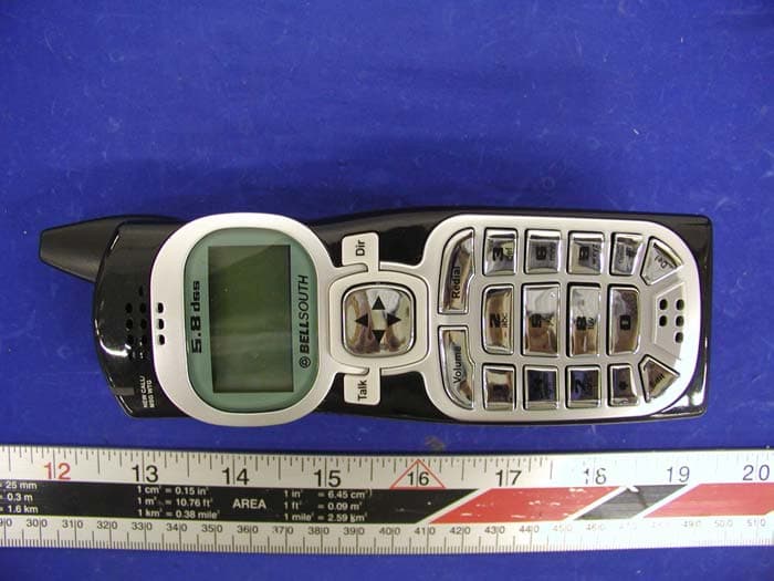
May 23, 2004Digital Cordless Phone � Handset Unit
Equipment Class
DTS - Digital Transmission System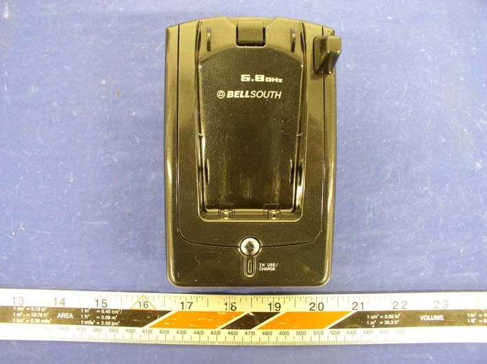
O63GH5815BALD04
Apr 15, 2004Analog Cordless Phone
Equipment Class
DXX - Part 15 Low Power Communication Device Transmitter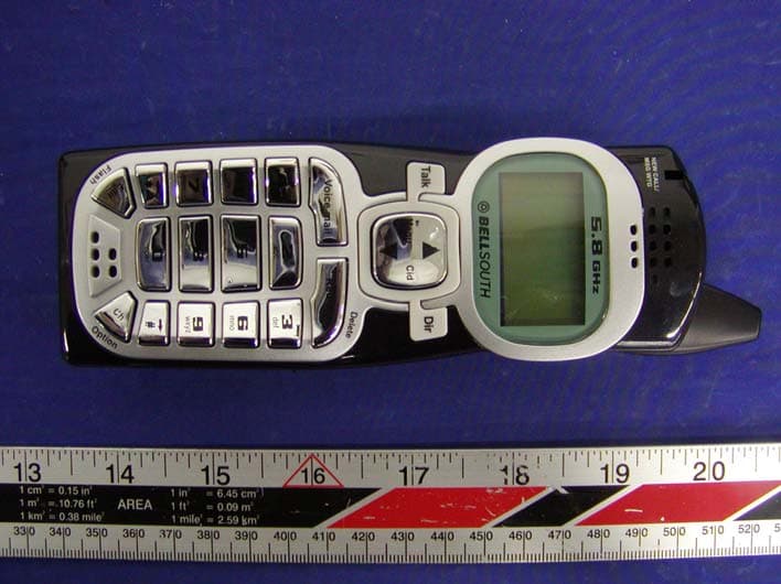
O63GH5815HALD04
Apr 15, 2004Analog Cordless Phone
Equipment Class
DXX - Part 15 Low Power Communication Device Transmitter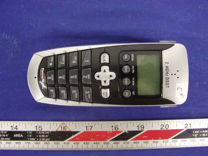
O63PM3320DLD04
Apr 05, 20042.4GHz Digital Spread-Spectrum Cordless Phone
Equipment Class
DTS - Digital Transmission System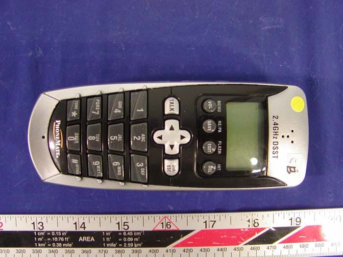
O63PM3375DLD04
Mar 29, 20042.4GHz Digital Spread-Spectrum Cordless Phone
Equipment Class
DTS - Digital Transmission System