O7J-GL2454AP-QA1802.11g Wireless Access Point/Ethernet Adapter
Global Sun Technology Inc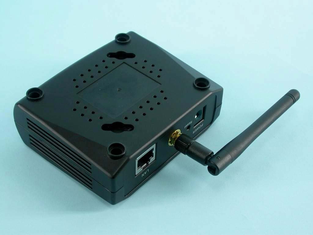
Click to zoom
Application Details
- Equipment Class
- DTS - Digital Transmission System
- Date of Grant
- Mar 09, 2004
- Application Purpose
- Original Equipment
- Date of Application
- Mar 09, 2004
- Equipment Note
- 802.11g Wireless Access Point/Ethernet Adapter
- Frequency Range
- 2412.00000000 - 2462.00000000
- Company
- Global Sun Technology Inc
- Country
- Taiwan
Documents & Files
Document Text
Text extracted from the exhibit documents filed with the FCC. Open a document above to read the original.
Users Manual
108Mbps Wireless Network Access Point USER MANUAL Contents 1. Product Feature......................................................................................................3 2. Getting Start...........................................................................................................3 2.1 Know the 108Mbps Wireless Ethernet Adapter.........................................3 2.2 Connect to the 108Mbps Wireless Ethernet Adapter.................................3 2.3 Configuration via Web Manager................................................................4 2.3.1 Access the Setting Menu................................................................4 2.3.2 Status..............................................................................................6 2.3.2 Basic Setting..................................................................................7 2.3.3 IP Setting........................................................................................8 2.3.4 Security..........................................................................................9 2.3.5 Tools.............................................................................................10 3. Configuration through the Utility........................................................................ 11 3.1 Link Information...................................................................................... 11 3.2 AP Settings...............................................................................................12 3.3 IP Setting..................................................................................................13 3.4 Security....................................................................................................14 1. Product Feature ● Compliance with IEEE 802.11g and 802.11b standards ● High efficient design mechanism to provide unbeatable performance ● Achieving data rate up to 54Mbps for 802.11g and 11Mps for 802.11b with wide range coverage ● Network security with WEP ● Quick and easy setup with Web-based management utility. 2. Getting Start 2.1 Know the 108Mbps Wireless Ethernet Adapter Ports: ● Power Receptor ● Reset Button ● RJ-45 Ethernet Port Straight through cable is required to connect with router or switch Cross-over cable is required to connect to computer directly LEDs: ● Power LED: ON when the unit is powered up ● WLAN LED: ON indicates WLAN is working; BLINK indicates wireless activity. 2.2 Connect to the 108Mbps Wireless Ethernet Adapter This wireless Ethernet adapter transforms the Ethernet-enabled devices to have the wireless function. The wireless Ethernet adapter enables wireless communication over your network. There are two examples shown as the below. Infrastructure Mode: Ad-Hoc Mode: 2.3 Configuration via Web Manager 2.3.1 Access the Setting Menu You could start to access the configuration menu anytime by opening a web browser window by typing the IP address of this access point. The default IP is 192.168.1.1. The below window will popup. Please enter the user name and password. Both of the default is “admin”. Now, the main menu screen is popup. 2.3.2 Status This page as below shows you the following information. Firmware Version: Shows the current firmware version. LAN: Shows the Mac address, IP address (default: 192.168.1.1), Subnet Mask, Gateway Address. The current LAN traffic calculated in terms of number of packets sent and received by AP through wired connection is also displayed. Wireless: Shows the Mac address, current SSID, the status of Encryption Function (Enable or Disable), the current using channel. The current wireless traffic calculated in terms of number of packets sent and received through wireless communication is also displayed. 2.3.2 Basic Setting This is the page allow you to change the access point. Mode: Operating mode. This Ethernet adapter supports infrastructure and Ad-Hoc mode. SSID: Service Set Identifier, which is a unique name shared among all clients and nodes in a wireless network. The SSID must be identical for each clients and nodes in the wireless network. Channel: The channel that AP will operate in. In Ad-Hoc mode, you can select the channel range of 1 to 11 for North America (FCC) domain, 1 to 13 for European (ETSI) domain and 1 to 14 for Japanese domain. Tx Rate: Select the data rate for data transmission. Default is auto. Authentication Type: The authentication type default is set to open system. It means the sender and receiver do not share secret Key for communication. Shared Key is the sender and receiver shares the common key for data communication, and the key is used for extended length of time. WEP Key: WEP data encryption feature. To disable WEP security, click on the “Disable” option. To enable WEP security, there are 2 types to select – 64bits and 128 bits. When it is selected, the key value must be entered in ASCII or HEX format. Apply: For the changes made to any of the items above to be effective, click “Apply”. The new settings are now been saved to Access Point and will be effective once the Access Point restarts. 2.3.3 IP Setting This page allows you to configure the IP of the wireless Ethernet adapter. The default IP address is 192.168.1.1 with the subnet mask of 255.255.255.0. You can type in other values for IP Address, Subnet Mask and Gateway and click “Apply” button for the changes to be effective. You can also set to obtain the IP from a DHCP server. Select the option “Obtain IP Automatically” and click “Apply” button for the changes to be effective. 2.3.4 Security This page is where you configure the security feature. Password: Allow you to change the new login password. Here are the necessary steps: 1. Enter the new password in the “AP Password New:” field. 2. Enter the new password again in the “Confirm” field. 3. Click “Apply” 2.3.5 Tools Four functions are provided in this page, Backup, Restore Settings, Restore default settings and Firmware Upgrade. Backup Settings: Cl…
Text truncated - open the document above for the full version.
Cover Letter(s)
Confidentiality letter.JPG (1653 x 2338 x 8)
Cover Letter(s)
FCC DoC.JPG (1653 x 2338 x 8)
External Photos
Page 1 CONSTRUCTION PHOTOS OF EUT Page 2 Page 3 Page 4 Page 5 Page 6
ID Label/Location Info
FCC ID Label Location
ID Label/Location Info
S / N: MAC: 29mm 39mm Made in Taiwan Model: GL2454AP-QA3 FCC ID: 07J-GL2454AP-QA1
Internal Photos
Page 7 Page 8 Page 9 Page 10 Page 11 Page 12
Operational Description
FCC ID: O7J-GL2454AP-QA1 Report No.RF921002R05A Operational Description This device is an 802.11g Wireless Access Point/802.11g Ethernet Adapter which operates in the 2.4GHz frequency spectrum with throughput of up to 54Mbps which OFDM technique will be applied. If the signal to noise radio is too poor which could not support 54Mbps, the 11Mbps data rate with CCK technique will be applied. The transmitter of the EUT is powered by power adapter and connected with managing computer through RJ45 port. The antenna is Dipole antenna with Reverse SMA antenna connector. Under normal use condition, the user has to keep at least 20cm separation distance between radiator and the body of the user. The other instruction, please have a look at the users manual.
RF Exposure Info
FCC ID: O7J-GL2454AP-QA1 Report No: SA921002R05A 1 FCC TEST REPORT REPORT NO.: SA921002R05A MODEL NO.: GL2454AP-QA1 ACCORDING: FCC Guidelines for Human Exposure IEEE C95.1 APPLICANT: GLOBAL SUN TECHNOLOGY INC. ADDRESS: NO.13 Tung Yuan Rd., Jung Li Industrial Park Jung Li City, Tao Yuan Hsien, Taiwan ISSUED BY: Advance Data Technology Corporation LAB LOCATION: 47 14th Lin, Chiapau Tsun, Linko, Taipei, Taiwan, R.O.C. FCC ID: O7J-GL2454AP-QA1 Report No: SA921002R05A 2 RF Exposure Measurement (Mobile Device) 1. Introduction In this document, we try to prove the safety of radiation harmfulness to the human body for our product. The limit for Maximum Permissible Exposure (MPE) specified in FCC 1.1310 is followed. The Gain of the antenna used in this product is measured in a Fully Anechoic Chamber (FAC) calibrated for antenna measurement in ADT, and also the maximum total power input to the antenna is measured. Through the Friis transmission formula and the maximum gain of the antenna, we can calculate the distance, away from the product, where the limit of MPE is reached. Although the Friis transmission formula is a far field assumption, the calculated result of that is an over-prediction for near field power density. We will take that as the worst case to specify the safety range. 2. RF Exposure Limit According to FCC 1.1310: The criteria listed in the following table shall be used to evaluate the environmental impact of human exposure to radio-frequency (RF) radiation as specified in 1.1307(b) LIMITS FOR MAXIMUM PERMISSIBLE EXPOSURE (MPE) Frequency Range (MHz) Electric Field Strength (V/m) Magnetic Field Strength (A/m) Power Density (mW/cm 2 ) Average Time (minutes) (A)Limits For Occupational / Control Exposures 300-1500......F/3006 1500-100,000......56 (B)Limits For General Population / Uncontrolled Exposure 300-1500......F/15006 1500-100,000......1.030 F = Frequency in MHz FCC ID: O7J-GL2454AP-QA1 Report No: SA921002R05A 3 3. Friis Formula Friis transmission formula: Pd = (Pout*G) / (4*pi*r 2 ) where Pd = power density in mW/cm 2 Pout = output power to antenna in mW G = gain of antenna in linear scale Pi = 3.1416 R = distance between observation point and center of the radiator in cm If we know the maximum Gain of the antenna and the total power input to the antenna, through the calculation, we will know the MPE value at distance 20cm. Ref.: David K. Cheng, Field and Wave Electromagnetics, Second Edition, Page 640, Eq. (11-133). 4 EUT Operating condition The software provided by Manufacturer enabled the EUT to transmit and receive data at lowest, middle and highest channel individually. 5. Classification This device is not fixed inside the host equipment, for normal use, it is easy to be re- located in the place where at least 20cm far away from the body of the user. Warning statement to the user for keeping at least 20cm or more separation distance with the antenna should be included in users manual. So, this device is classified as Mobile Device. FCC ID: O7J-GL2454AP-QA1 Report No: SA921002R05A 4 6 Test Results 6.1 Antenna Gain The maximum Gain measured in Fully Anechoic Chamber is 1.8dBi or 1.514 (numeric). 6.2 Output Power Into Antenna & MPE value at distance 20cm: Mode CCK Channel Channel Frequency (MHz) Output Power to Antenna (mW) Power Density (mW/cm 2 ) Limit of Power Density (mW/cm 2 ) 1241250.3500.0151.0 6243750.5820.0151.0 11246250.0030.0151.0 Mode OFDM Channel Channel Frequency (MHz) Output Power to Antenna (mW) Power Density (mW/cm 2 ) Limit of Power Density (mW/cm 2 ) 1241250.9330.0151.0 6243751.5230.0161.0 11246249.8880.0151.0
Test Report
FCC ID: O7J-GL2454AP-QA1 Report No.: RF921002R05A1Issued: February 20, 2004 Reference No.: RF921002R05 FCC TEST REPORT REPORT NO.: RF921002R05A MODEL NO.: GL2454AP-QA1 (Please refer to page 6 for other model names) RECEIVED: NA TESTED: Oct. 01, 2003 ~ Oct. 06, 2003 APPLICANT: GLOBAL SUN TECHNOLOGY INC. ADDRESS: NO.13 Tung Yuan Rd., Jung Li Industrial Park Jung Li City, Tao Yuan Hsien, Taiwan ISSUED BY: Advance Data Technology Corporation LAB LOCATION: 47 14th Lin, Chiapau Tsun, Linko, Taipei, Taiwan, R.O.C. This test report consists of 68 pages in total. It may be duplicated completely for legal use with the approval of the applicant. It should not be reproduced except in full, without the written approval of our laboratory. The client should not use it to claim product endorsement by CNLA or any government agencies. The test results in the report only apply to the tested sample. 0528 ILAC MRA FCC ID: O7J-GL2454AP-QA1 Report No.: RF921002R05A2Issued: February 20, 2004 Reference No.: RF921002R05 Table of Contents 1CERTIFICATION ........................................................................................... 4 2SUMMARY OF TEST RESULTS................................................................... 5 3GENERAL INFORMATION ........................................................................... 6 3.1GENERAL DESCRIPTION OF EUT.............................................................. 6 3.2DESCRIPTION OF TEST MODES................................................................ 8 3.3GENERAL DESCRIPTION OF APPLIED STANDARDS ............................... 8 3.4DESCRIPTION OF SUPPORT UNITS .......................................................... 9 3.5CONFIGURATION OF SYSTEM UNDER TEST........................................... 9 4TEST TYPES AND RESULTS..................................................................... 10 4.1CONDUCTED EMISSION MEASUREMENT .............................................. 10 4.1.1LIMITS OF CONDUCTED EMISSION MEASUREMENT............................ 10 4.1.2TEST INSTRUMENTS ................................................................................ 10 4.1.3TEST PROCEDURES..................................................................................11 4.1.4DEVIATION FROM TEST STANDARD ........................................................11 4.1.5TEST SETUP .............................................................................................. 12 4.1.6EUT OPERATING CONDITIONS................................................................ 12 4.1.7TEST RESULTS.......................................................................................... 13 4.2RADIATED EMISSION MEASUREMENT ................................................... 19 4.2.1LIMITS OF RADIATED EMISSION MEASUREMENT................................. 19 4.2.2TEST INSTRUMENTS ................................................................................ 20 4.2.3TEST PROCEDURES................................................................................. 21 4.2.4DEVIATION FROM TEST STANDARD ....................................................... 21 4.2.5TEST SETUP .............................................................................................. 22 4.2.6EUT OPERATING CONDITIONS................................................................ 22 4.2.7TEST RESULTS.......................................................................................... 23 4.2.8TEST RESULTS (FOR CCK)...................................................................... 25 4.2.9TEST RESULTS (FOR OFDM) ................................................................... 28 4.36dB BANDWIDTH MEASUREMENT .......................................................... 31 4.3.1LIMITS OF 6dB BANDWIDTH MEASUREMENT ........................................ 31 4.3.2TEST INSTRUMENTS ................................................................................ 31 4.3.3TEST PROCEDURE ................................................................................... 32 4.3.4DEVIATION FROM TEST STANDARD ....................................................... 32 4.3.5TEST SETUP .............................................................................................. 32 4.3.6EUT OPERATING CONDITIONS................................................................ 32 4.3.7TEST RESULTS.......................................................................................... 33 4.4MAXIMUM PEAK OUTPUT POWER .......................................................... 41 4.4.1LIMITS OF MAXIMUM PEAK OUTPUT POWER MEASUREMENT ........... 41 FCC ID: O7J-GL2454AP-QA1 Report No.: RF921002R05A3Issued: February 20, 2004 Reference No.: RF921002R05 4.4.2TEST INSTRUMENTS ................................................................................ 41 4.4.3TEST PROCEDURES................................................................................. 42 4.4.4DEVIATION FROM TEST STANDARD ....................................................... 42 4.4.5TEST SETUP .............................................................................................. 42 4.4.6EUT OPERATING CONDITIONS................................................................ 42 4.4.7TEST RESULTS.......................................................................................... 43 4.5POWER SPECTRAL DENSITY MEASUREMENT...................................... 44 4.5.1LIMITS OF POWER SPECTRAL DENSITY MEASUREMENT ................... 44 4.5.2TEST INSTRUMENTS ................................................................................ 44 4.5.3TEST PROCEDURE ................................................................................... 45 4.5.4DEVIATION FROM TEST STANDARD ....................................................... 45 4.5.5TEST SETUP .............................................................................................. 45 4.5.6EUT OPERATING CONDITIONS.......................................................…
Text truncated - open the document above for the full version.
Test Setup Photos
FCC ID: O7J-GL2454AP-QA1 Report No.: RF921002R05A66Issued: February 20, 2004 Reference No.: RF921002R05 5 PHOTOGRAPHS OF THE TEST CONFIGURATION CONDUCTED EMISSION TEST FCC ID: O7J-GL2454AP-QA1 Report No.: RF921002R05A67Issued: February 20, 2004 Reference No.: RF921002R05 RADIATED EMISSION TEST
Contact Information
Applicant
Alex Wu(CTO)
Technical Contact
Advance Data Technology CorporationEllis Wu
[email protected]+886 3 318 3232
No. 19 Hwa Ya 2nd rd. Kueishan · Taoyuan · Taiwan
Test Firm
Bureau Veritas CPS (H.K.) Ltd. Taoyuan BranchRichard Chen
Technical Specifications
| # | Rule Parts | Frequency Range | Power Output |
|---|---|---|---|
| 1 | 15C | 2.41 GHz - 2.46 GHz | 52.00 mW |
Other Applications from Global Sun Technology Inc

O7J-WLUD2554-17A
Apr 17, 2005802.11 a+g Wireless USB Dongle
Equipment Class
NII - Unlicensed National Information Infrastructure TX
O7J-WL012454-25M
Oct 24, 2004802.11g Wireless LAN Network Adapter
Equipment Class
DTS - Digital Transmission System
O7J-WLUD2454-13I
Sep 30, 2004802.11g Wireless USB Dongle
Equipment Class
DTS - Digital Transmission System
O7J-WLMP2454-1A3
Sep 25, 2004802.11g Wireless mini-PCI Module
Equipment Class
DTS - Digital Transmission System
O7J-WLRT2454NMA40
Jul 29, 2004AT&T Plug&Share 54Mbps Wireless Router
Equipment Class
DTS - Digital Transmission System