O7J-GL2454MU-0IHighSpeed 2.4GHz Wireless USB Adapter
Global Sun Technology Inc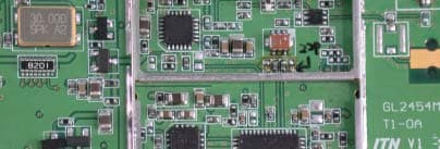
Click to zoom
Application Details
- Equipment Class
- DTS - Digital Transmission System
- Date of Grant
- Sep 18, 2003
- Application Purpose
- Original Equipment
- Date of Application
- Sep 18, 2003
- Equipment Note
- HighSpeed 2.4GHz Wireless USB Adapter
- Frequency Range
- 2412.00000000 - 2462.00000000
- Company
- Global Sun Technology Inc
- Country
- Taiwan
Documents & Files
Document Text
Text extracted from the exhibit documents filed with the FCC. Open a document above to read the original.
Users Manual
GL-2454MU-0I Quick Installation Guide 1. Package Content ● GL2454MU-0I USB Wireless Adapter ● CD-ROM ● Mini USB Cable If any of the above items is missing, please immediately contact your dealer. 2. System Requirements ● A PC system ( desktop or laptop) with an available USB port ● At least 32MB memory and a 300 MHz processor ● OS: Windows 98SE; Windows ME; Windows 2000; Windows XP ● A wireless access point (infrastructure mode) or another wireless (Ad-Hoc mode) 3. Installation Quide 1. Turn on your computer and insert the CD in the CD-ROM driver. Follow the instruction shown on the pop-up windows: choose destination location. Select your CD-ROM driver. 2. The pop-up window will show the setup status during the installation. 3. Once it is done, the system will ask if you like to re-start the computer immediately. Please press YES. 4. At the meantime or after the restart, please connect the USB cable A type into the USB port on your PC. 5. Connect the mini USB with the Wireless USB adapter as well. 6. Then, the Windows will install the driver automatically. 7. The utility icon will appear once you have installed the driver. It will be shown in green if the installation is successful. GL-2454MU-0I Quick Installation Guide 4. Utility Configuration 4.1 Link Information Status: Displays the current connection state of the GL2454MU-0I. SSID: The Service Set Identifier is the name assigned to the wireless network. The factory SSID setting is set to default. Tx Rate: The default setting is Auto; Channel: The default setting is 6. Link Quality: Displays the wireless signal strength for the GL2454MU-0I wireless connection to the access point. Data Rate: Displays the statistics of the data that is transmitted and received. A new icon will appear in your Icon tray. Double-click on the icon shown at right. The screen below will be displayed with the following default settings: 4.2 Configuration SSID: The Service Set Identifier is the name assigned to the wireless network. The factory SSID setting is set to default. Make changes here to match the SSID on the existing Wireless Router or Access Point. Wireless Mode: Infrastructure is the factory default setting. Ad-Hoc mode is used for peer-to-peer networking. See the Getting Started section in this manual for examples of these network types. Channel: The default channel setting is channel 6. In Infrastructure mode, the GL2454MU-0I will automatically select the channel to match the channel setting for the selected GL-2454MU-0I Quick Installation Guide Access Point. In Ad Hoc mode, the channel must be manually set to the same channel for each wireless adapter Tx Rate: You can adjust the transmission rate to get the best signal possible depending on your usage and your environment. The Tx Rate will be determined automatically by signal strength. Default is set to Auto. Preamble: Select Long or Short Preamble. The Preamble defines the length of the CRC block (Cyclic Redundancy Check is a common technique for detecting data transmission errors) for communication between the Access Point and the roaming wireless Network adapters Power Mode: Select from three modes: Continuous Access Mode - this default setting consumes the most power Maximum Power Save - this setting consumes the least power Power Save - this setting consumes a moderate amount of power 4.3 Encryption Data Encryption: Enable encryption by clicking in the box. Data encryption is de-selected as the default setting. Default Key : Enter a key in either ASCII (e.g., a word) or hexadecimal format. Select one of the 4 keys that you have created to be the default key. Authorization Mode: Click Apply if you have made any changes Open Authentication - communicates the key across the network Shared Authentication - allows communication only with other devices with identical WEP settings Auto - will automatically adjust to the Authentication mode of the wireless Access Point or Router 4.4 Site Survey Available Networks: GL-2454MU-0I Quick Installation Guide The top section of the window displays the Available Networks. Scroll up and down the list and highlight the network to which you wish to connect. Click on the Connect button. Profiles: In the lower half of the screen, you can manage the profiles that you have created for the wireless network at home, at the office and in public places. Scroll up and down and highlight the profile that you wish to configure. You can ADD or REMOVE a profile, or configure the Properties of the profile in order to connect with an available network. 4.5 About The About tab displays the utility and the firmware versions. Federal Communication Commission Interference Statement This equipment has been tested and found to comply with the limits for a Class B digital device, pursuant to Part 15 of the FCC Rules. These limits are designed to provide reasonable protection against harmful interference in a residential installation. This equipment generates, uses and can radiate radio frequency energy and, if not installed and used in accordance with the instructions, may cause harmful interference to radio communications. However, there is no guarantee that interference will not occur in a particular installation. If this equipment does cause harmful interference to radio or television reception, which can be determined by turning the equipment off and on, the user is encouraged to try to correct the interference by one of the following measures: - Reorient or relocate the receiving antenna. - Increase the separation between the equipment and receiver. - Connect the equipment into an outlet on a circuit different from that to which the receiver is connected. - Consult the dealer or an experienced radio/TV technician for help. This device complies with Part 15 of the FCC Rules. Operation is subject to the following two conditions: (1) This device may not cause harmful interference, and (2) this device must accept any interference received, including interference that may cause und…
Text truncated - open the document above for the full version.
Cover Letter(s)
[email protected] www.adt.com.tw ADVANCE DATA TECHNOLOGY CORPORATION FEDERAL COMMUNICATIONS COMMISSION DECLARATION OF CONFORMITY (DoC) FOR THE FOLLOWING EQUIPMENT: PRODUCT NAME: HighSpeed 2.4GHz Wireless USB Adapter (Receiver Part) MODEL NO.: GL2454MU-0I, DWL-G120 TRADE NAME: GLOBAL SUN , D-Link I S HEREWITH CONFIRMED TO BE IN COMPLIANCE WITH THE REQUIREMENTS OF ANSI C63.4 & FCC PART 15 REGULATIONS. THE TEST RESULT HAS BEEN SHOWN IN THE ADT TEST REPORT WITH NUMBER : D920831R01 A ND THIS COMPLIANCE IS SUBJECT TO THE FOLLOWING TWO CONDITIONS: (1) T HIS DEVICE MAY NOT CAUSE HARMFUL INTERFERENCE AND, (2) T HIS DEVICE MUST ACCEPT ANY INTERFERENCE RECEIVED, INCLUDING INTERFERENCE THAT MAY CAUSE UNDESIRED OPERATION . THE FOLLOWING LOCAL IMPORTER IS RESPONSIBLE FOR THIS DECLARATION: ManufacturerUSA Local Representative Company name: GLOBAL SUN Technology, INC. Contact Person: Kent, Chiu Address: NO.13 Tung Yuan Rd., Jung Li Industrial Park Jung Li City, Tao Yuan Hsien, Taiwan Address: 22 Creek Rd #100,Irvine, CA 92604 Contact Person: Alan Lin Title: Field Application Engineer Signature: Tel/Fax: Tel: 1 714-9151952 Fax: 1 949-3871792 Title: Director Tel/Fax: Tel: +886-2-8522-7155 Fax: +886-2-8522-7156
Cover Letter(s)
GLOBAL SUN Technology, INC. NO.13 Tung Yuan Rd., Jung Li Industrial Park Jung Li City, Tao Yuan Hsien, Taiwan, R.O.C TEL.:+886+2-8522-7155 FAX:+886+2-8522-7156 FCC ID: O7J-GL2454MU-0I Federal Communications Commission Authorization and Evaluation Division Confidentiality Request Pursuant to Sections 0.457 and 0.459 of the Commission’s Rules, the Applicant hereby requests confidential treatment of information accompanying this Application as outlined below: Schematics Block Diagram The above materials contain trade secrets and proprietary information not customarily released to the public. The public disclosure of these matters might be harmful to the Applicant and provide unjustified benefits to its competitors. The Applicant understands that pursuant to Rule 0.457, disclosure of this Application and all accompanying documentation will not be made before the date of the Grant for this application. Sincerely ------------------------------------------- Alan Lin / Director GLOBAL SUN Technology, INC. TEL.:+886+2-8522-7155 FAX:+886+2-8522-7156 e-mail: [email protected]
External Photos
Page 1 CONSTRUCTION PHOTOS OF EUT Page 2 Page 3 Page 4
ID Label/Location Info
Label Location
Internal Photos
Page 5 Page 6 Page 7 Page 8 Page 9 Page 10
Operational Description
FCC ID: O7J-GL2454MU-0I ADT No.920831R01 Operational Description This device is a HighSpeed 2.4GHz Wireless USB Adapter which operates in 2.4GHz band, the maximum data rate could be up to 54Mbps which OFDM technique will be applied. If the signal to noise radio is too poor which could not support 54Mbps, the 11Mbps data rate with CCK technique will be applied. The transmitter of the EUT is powered by host equipment via a PCMCIA interface. The antenna is Diople antenna. There is no antenna connector. The other instruction, please have a look at the users manual.
RF Exposure Info
Report No: 920831R01 1 RF EXPOSURE REPORT REPORT NO.: RF920831R01 MODEL NO.: GL2454MU-0I ACCORDING: FCC Guidelines for Human Exposure IEEE C95.1 APPLICANT: Global Sun Technology, Inc. ADDRESS: No.13, Tung Yuan Rd., Jung Li Industrial Park, Jung Li City, Taoyuan Hsien, Taiwan, R.O.C. ISSUED BY: Advance Data Technology Corporation LAB LOCATION: 47 14th Lin, Chiapau Tsun, Linko, Taipei, Taiwan, R.O.C. 0528 ILAC MRA Lab Code: 200102-0 Report No: 920831R01 2 RF Exposure Measurement (Mobile Device) 1. Introduction In this document, we try to prove the safety of radiation harmfulness to the human body for our product. The limit for Maximum Permissible Exposure (MPE) specified in FCC 1.1310 is followed. The Gain of the antenna used in this product is measured in a Fully Anechoic Chamber (FAC) calibrated for antenna measurement in ADT, and also the maximum total power input to the antenna is measured. Through the Friis transmission formula and the maximum gain of the antenna, we can calculate the distance, away from the product, where the limit of MPE is reached. Although the Friis transmission formula is a far field assumption, the calculated result of that is an over-prediction for near field power density. We will take that as the worst case to specify the safety range. 2. RF Exposure Limit According to FCC 1.1310: The criteria listed in the following table shall be used to evaluate the environmental impact of human exposure to radio-frequency (RF) radiation as specified in 1.1307(b) LIMITS FOR MAXIMUM PERMISSIBLE EXPOSURE (MPE) Frequency Range (MHz) Electric Field Strength (V/m) Magnetic Field Strength (A/m) Power Density (mW/cm 2 ) Average Time (minutes) (A)Limits For Occupational / Control Exposures 300-1500......F/3006 1500-100,000......56 (B)Limits For General Population / Uncontrolled Exposure 300-1500......F/15006 1500-100,000......1.030 F = Frequency in MHz Report No: 920831R01 3 3. Friis Formula Friis transmission formula : Pd = (Pout*G) / (4*pi*r 2 ) where Pd = power density in mW/cm 2 Pout = output power to antenna in mW G = gain of antenna in linear scale Pi = 3.1416 R = distance between observation point and center of the radiator in cm If we know the maximum Gain of the antenna and the total power input to the antenna, through the calculation, we will know the MPE value at distance r. Ref. : David K. Cheng, Field and Wave Electromagnetics, Second Edition, Page 640, Eq. (11-133). 4 EUT Operating condition The software provided by Manufacturer enabled the EUT to transmit and receive data at lowest, middle and highest channel individually. 5. Classification The antenna of the product, under normal use condition, is at least 20cm away from the body of the user. Warming statement for keeping 20cm separation distance and the prohibition of operating next to a person has been printed on the user’s manual. So, this product is classified as the Mobile Device. Report No: 920831R01 4 6 Test Results 6.1 Antenna Gain The maximum Gain measured in Fully Anechoic Chamber are 1.5dBi or 1.413 (numeric). 6.2 Output Power Into Antenna & RF Exposure value at distance 20cm: for CCK technique Channel Channel Frequency (MHz) Output Power to Antenna (mW) Power Density (mW/cm 2 ) Limit of Power Density (mW/cm 2 ) 1241280.7240.0231.0 6243781.4700.0231.0 11246280.7240.0231.0 for OFDM technique Channel Channel Frequency (MHz) Output Power to Antenna (mW) Power Density (mW/cm 2 ) Limit of Power Density (mW/cm 2 ) 1241293.7560.0261.0 6243796.3830.0271.0 11246297.0510.0271.0
Test Report
FCC ID: O7J-GL2454MU-0I Report No.: RF920831R011Issued: September 16, 2003 FCC TEST REPORT REPORT NO.: RF920831R01 MODEL NO.: GL2454MU-0I RECEIVED: August 31, 2003 TESTED: Sep. 14~Sep.15, 2003 APPLICANT: GLOBAL SUN TECHNOLOGY INC. ADDRESS: NO.13 Tung Yuan Rd., Jung Li Industrial Park Jung Li City, Tao Yuan Hsien , Taiwan ISSUED BY: Advance Data Technology Corporation LAB LOCATION: 47 14th Lin, Chiapau Tsun, Linko, Taipei, Taiwan, R.O.C. This test report consists of 63 pages in total. It may be duplicated completely for legal use with the approval of the applicant. It should not be reproduced except in full, without the written approval of our laboratory. The client should not use it to claim product endorsement by CNLA, NVLAP or any government agencies. The test results in the report only apply to the tested sample. 0528 ILAC MRA Lab Code: 200102-0 FCC ID: O7J-GL2454MU-0I Report No.: RF920831R012Issued: September 16, 2003 Table of Contents 1CERTIFICATION ........................................................................................... 4 2SUMMARY OF TEST RESULTS................................................................... 5 3GENERAL INFORMATION ........................................................................... 6 3.1GENERAL DESCRIPTION OF EUT.............................................................. 6 3.2DESCRIPTION OF TEST MODES................................................................ 7 3.3GENERAL DESCRIPTION OF APPLIED STANDARDS ............................... 7 3.4DESCRIPTION OF SUPPORT UNITS .......................................................... 8 4TEST TYPES AND RESULTS....................................................................... 9 4.1CONDUCTED EMISSION MEASUREMENT ................................................ 9 4.4.1LIMITS OF CONDUCTED EMISSION MEASUREMENT.............................. 9 4.4.2TEST INSTRUMENTS .................................................................................. 9 4.4.3TEST PROCEDURES................................................................................. 10 4.4.4TEST SETUP .............................................................................................. 10 4.4.5EUT OPERATING CONDITIONS.................................................................11 4.4.6TEST RESULTS.......................................................................................... 12 4.2RADIATED EMISSION MEASUREMENT ................................................... 18 4.4.7LIMITS OF RADIATED EMISSION MEASUREMENT................................. 18 4.4.8TEST INSTRUMENTS ................................................................................ 19 4.4.9TEST PROCEDURES................................................................................. 20 4.4.10 TEST SETUP .............................................................................................. 21 4.4.11 EUT OPERATING CONDITIONS................................................................ 21 4.4.12 TEST RESULTS.......................................................................................... 22 4.4.13 TEST RESULTS (FOR CCK)...................................................................... 24 4.4.14 TEST RESULTS (FOR OFDM) ................................................................... 27 4.36dB BANDWIDTH MEASUREMENT .......................................................... 30 4.4.15 LIMITS OF 6dB BANDWIDTH MEASUREMENT ........................................ 30 4.4.16 TEST INSTRUMENTS ................................................................................ 30 4.4.17 TEST PROCEDURE ................................................................................... 31 4.4.18 TEST SETUP .............................................................................................. 31 4.4.19 EUT OPERATING CONDITIONS................................................................ 31 4.4.20 TEST RESULTS (FOR CCK)...................................................................... 32 4.4.21 TEST RESULTS (FOR OFDM) ................................................................... 36 4.4MAXIMUM PEAK OUTPUT POWER .......................................................... 40 4.4.1LIMITS OF MAXIMUM PEAK OUTPUT POWER MEASUREMENT ........... 40 4.4.2TEST INSTRUMENTS ................................................................................ 40 FCC ID: O7J-GL2454MU-0I Report No.: RF920831R013Issued: September 16, 2003 4.4.3TEST PROCEDURES................................................................................. 41 4.4.4DEVIATION FROM TEST STANDARD ....................................................... 41 4.4.5TEST SETUP .............................................................................................. 41 4.4.6EUT OPERATING CONDITIONS................................................................ 41 4.4.7TEST RESULTS (FOR CCK)...................................................................... 42 4.4.8TEST RESULTS (FOR OFDM) ................................................................... 42 4.5POWER SPECTRAL DENSITY MEASUREMENT...................................... 43 4.5.1LIMITS OF POWER SPECTRAL DENSITY MEASUREMENT ................... 43 4.5.2TEST INSTRUMENTS ................................................................................ 43 4.5.3TEST PROCEDURE ................................................................................... 44 4.5.4TEST SETUP .............................................................................................. 44 4.5.5EUT OPERATING CONDITIONS................................................................ 44 4.5.6TEST RESULTS (FOR CCK)...................................................................... 45 4.5.7TEST RESULTS (FOR OFDM) ................................................................... 49 4.6BAND EDGES MEASUREMENT ................................................................ 53 4.6.1LIMITS OF BAND EDGES MEASUREMENT ...…
Text truncated - open the document above for the full version.
Test Setup Photos
FCC ID: O7J-GL2454MU-0I Report No.: RF920831R0161Issued: September 16, 2003 5 PHOTOGRAPHS OF THE TEST CONFIGURATION CONDUCTED EMISSION TEST FCC ID: O7J-GL2454MU-0I Report No.: RF920831R0162Issued: September 16, 2003 RADIATED EMISSION TEST
Contact Information
Applicant
Alex Wu(CTO)
Technical Contact
Advance Data Technology Corp.Ellis Wu
[email protected]+886-3-327-0910
13-1 Lane 19 WenShan 3rd Street · Toayuan · Taiwan
Test Firm
Bureau Veritas CPS (H.K.) Ltd. Taoyuan BranchTommy Wu
Technical Specifications
| # | Rule Parts | Frequency Range | Power Output |
|---|---|---|---|
| 1 | 15C | 2.41 GHz - 2.46 GHz | 97.00 mW |
Other Applications from Global Sun Technology Inc

O7J-WLUD2554-17A
Apr 17, 2005802.11 a+g Wireless USB Dongle
Equipment Class
NII - Unlicensed National Information Infrastructure TX
O7J-WL012454-25M
Oct 24, 2004802.11g Wireless LAN Network Adapter
Equipment Class
DTS - Digital Transmission System
O7J-WLUD2454-13I
Sep 30, 2004802.11g Wireless USB Dongle
Equipment Class
DTS - Digital Transmission System
O7J-WLMP2454-1A3
Sep 25, 2004802.11g Wireless mini-PCI Module
Equipment Class
DTS - Digital Transmission System
O7J-WLRT2454NMA40
Jul 29, 2004AT&T Plug&Share 54Mbps Wireless Router
Equipment Class
DTS - Digital Transmission System