O7J-GL5054MP-AAWireless 54Mbps MiniPCI Card
Global Sun Technology Inc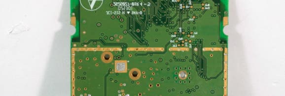
Click to zoom
Application Details
- Equipment Class
- NII - Unlicensed National Information Infrastructure TX
- Date of Grant
- Sep 12, 2002
- Application Purpose
- Original Equipment
- Date of Application
- Sep 12, 2002
- Equipment Note
- Wireless 54Mbps MiniPCI Card
- Frequency Range
- 5725.00000000 - 5825.00000000
- Company
- Global Sun Technology Inc
- Country
- Taiwan
Documents & Files
Document Text
Text extracted from the exhibit documents filed with the FCC. Open a document above to read the original.
Users Manual
WLAN 54Mbps MiniPCI Card USER MANUAL Version 0.1, August 5, 2002 Federal Communication Commission Interference Statement This equipment has been tested and found to comply with the limits for a Class B digital device, pursuant to Part 15 of the FCC Rules. These limits are designed to provide reasonable protection against harmful interference in a residential installation. This equipment generates, uses and can radiate radio frequency energy and, if not installed and used in accordance with the instructions, may cause harmful interference to radio communications. However, there is no guarantee that interference will not occur in a particular installation. If this equipment does cause harmful interference to radio or television reception, which can be determined by turning the equipment off and on, the user is encouraged to try to correct the interference by one of the following measures: - Reorient or relocate the receiving antenna. - Increase the separation between the equipment and receiver. - Connect the equipment into an outlet on a circuit different from that to which the receiver is connected. - Consult the dealer or an experienced radio/TV technician for help. FCC Caution: Any changes or modifications not expressly approved by the party responsible for compliance could void the user's authority to operate this equipment. (1) The devices are restricted to indoor operations within the 5.15 to 5.25GHz range. (2) For this device to operate in the 5.15 to 5.25GHz, so the devices must use integral antennas. This device complies with Part 15 of the FCC Rules. Operation is subject to the following two conditions: (1) This device may not cause harmful interference, and (2) this device must accept any interference received, including interference that may cause undesired operation. IMPORTANT NOTE: FCC Radiation Exposure Statement: This equipment complies with FCC radiation exposure limits set forth for an uncontrolled environment. This equipment should be installed and operated with minimum distance 20cm between the radiator & your body. This transmitter must not be co-located or operating in conjunction with any other antenna or transmitter. This device is intended only for OEM integrators under the following conditions: 1) The antenna must be installed such that 20 cm is maintained between the antenna and users, and 2) The transmitter module may not be co-located with any other transmitter or antenna. As long as 2 conditions above are met, further transmitter test will not be required. However, the OEM integrator is still responsible for testing their end-product for any additional compliance requirements required with this module installed (for example, digital device emissions, PC peripheral requirements, etc.). IMPORTANT NOTE: In the event that these conditions can not be met (for example certain laptop configurations or co-location with another transmitter), then the FCC authorization is no longer considered valid and the FCC ID can not be used on the final product. In these circumstances, the OEM integrator will be responsible for re- evaluating the end product (including the transmitter) and obtaining a separate FCC authorization. End Product Labeling This transmitter module is authorized only for use in device where the antenna may be installed such that 20 cm may be maintained between the antenna and users (for example access points, routers, wireless ADSL modems, and similar equipment). The final end product must be labeled in a visible area with the following: “Contains TX FCC ID: O7J-GL5054MP-AA”. Manual Information That Must be Included The users manual for end users must include the following information in a prominent location “ IMPORTANT NOTE: To comply with FCC RF exposure compliance requirements, the antenna used for this transmitter must be installed to provide a separation distance of at least 20 cm from all persons and must not be co-located or operating in conjunction with any other antenna or transmitter. PCI C ARD D RIVER I NSTALLATION 1. Insert the WLAN 54MBPS miniPCI CARD into the miniPCI slot of notebook PC, as described in the preceding section. Then insert the driver CD into the CD-ROM. 2. Wait for the following dialog box to appear. Choose “Install from a list or specific location (Advanced),” and click Next to continue. 3. Under “Search for the best driver in these locations,” choose “Include this location in the search” and click Browse to find the location of the NDIS driver. When the driver location has been identified, click Next to continue. 4. The NDIS evaluation driver currently does not have a digital signature from Microsoft. Therefore, Windows XP shows a warning message. Click Continue Anyway to proceed with driver installation. 5. Click Finish to complete driver installation, and refer to “Device configuration” for device configuration. 6. Go to Device Manager, right-click “Wireless Network Adapter,” and select Properties to access to the properties of the adapter. 6. Configuration additions, modifications, and deletions are made under the “Settings” tab of “Wireless Network Adapter Properties.”Select one of the configurations under the configuration, click Modify or New and complete the steps in “Infrastructure Mode” or “Ad Hoc Mode”to set up the station to work in infrastructure mode or ad hoc mode, respectively. Selecting Encryption Types Atheros supports two encryption types; Wired Equivalent Privacy (WEP) and Advanced Encryption Security (AES). By default, the STA is set to auto and will first attempt to use AES and will only use WEP if AP only supports, or is configured for WEP only. 1. Use the Advanced tab on the “ Wireless Network Adapter” dialog to change the encryption type. Infrastructure mode 1. Under the“General”tab, make sure the“Locally Administered Address” checkbox is unchecked. 2. Usually, infrastructure mode is used in an enterprise environment where APs are installed and maintained by corporate IT staff. Much of the data in the e…
Text truncated - open the document above for the full version.
Users Manual
WLAN 54Mbps MiniPCI Card USER MANUAL Version 0.1, August 5, 2002 Federal Communication Commission Interference Statement This equipment has been tested and found to comply with the limits for a Class B digital device, pursuant to Part 15 of the FCC Rules. These limits are designed to provide reasonable protection against harmful interference in a residential installation. This equipment generates, uses and can radiate radio frequency energy and, if not installed and used in accordance with the instructions, may cause harmful interference to radio communications. However, there is no guarantee that interference will not occur in a particular installation. If this equipment does cause harmful interference to radio or television reception, which can be determined by turning the equipment off and on, the user is encouraged to try to correct the interference by one of the following measures: - Reorient or relocate the receiving antenna. - Increase the separation between the equipment and receiver. - Connect the equipment into an outlet on a circuit different from that to which the receiver is connected. - Consult the dealer or an experienced radio/TV technician for help. FCC Caution: Any changes or modifications not expressly approved by the party responsible for compliance could void the user's authority to operate this equipment. (1) The devices are restricted to indoor operations within the 5.15 to 5.25GHz range. (2) For this device to operate in the 5.15 to 5.25GHz, so the devices must use integral antennas. This device complies with Part 15 of the FCC Rules. Operation is subject to the following two conditions: (1) This device may not cause harmful interference, and (2) this device must accept any interference received, including interference that may cause undesired operation. IMPORTANT NOTE: FCC Radiation Exposure Statement: This equipment complies with FCC radiation exposure limits set forth for an uncontrolled environment. This equipment should be installed and operated with minimum distance 20cm between the radiator & your body. This transmitter must not be co-located or operating in conjunction with any other antenna or transmitter. This device is intended only for OEM integrators under the following conditions: 1) The antenna must be installed such that 20 cm is maintained between the antenna and users, and 2) The transmitter module may not be co-located with any other transmitter or antenna. As long as 2 conditions above are met, further transmitter test will not be required. However, the OEM integrator is still responsible for testing their end-product for any additional compliance requirements required with this module installed (for example, digital device emissions, PC peripheral requirements, etc.). IMPORTANT NOTE: In the event that these conditions can not be met (for example certain laptop configurations or co-location with another transmitter), then the FCC authorization is no longer considered valid and the FCC ID can not be used on the final product. In these circumstances, the OEM integrator will be responsible for re- evaluating the end product (including the transmitter) and obtaining a separate FCC authorization. End Product Labeling This transmitter module is authorized only for use in device where the antenna may be installed such that 20 cm may be maintained between the antenna and users (for example access points, routers, wireless ADSL modems, and similar equipment). The final end product must be labeled in a visible area with the following: “Contains TX FCC ID: O7J-GL5054MP-AA”. Manual Information That Must be Included The users manual for end users must include the following information in a prominent location “ IMPORTANT NOTE: To comply with FCC RF exposure compliance requirements, the antenna used for this transmitter must be installed to provide a separation distance of at least 20 cm from all persons and must not be co-located or operating in conjunction with any other antenna or transmitter. PCI C ARD D RIVER I NSTALLATION 1. Insert the WLAN 54MBPS miniPCI CARD into the miniPCI slot of notebook PC, as described in the preceding section. Then insert the driver CD into the CD-ROM. 2. Wait for the following dialog box to appear. Choose “Install from a list or specific location (Advanced),” and click Next to continue. 3. Under “Search for the best driver in these locations,” choose “Include this location in the search” and click Browse to find the location of the NDIS driver. When the driver location has been identified, click Next to continue. 4. The NDIS evaluation driver currently does not have a digital signature from Microsoft. Therefore, Windows XP shows a warning message. Click Continue Anyway to proceed with driver installation. 5. Click Finish to complete driver installation, and refer to “Device configuration” for device configuration. 6. Go to Device Manager, right-click “Wireless Network Adapter,” and select Properties to access to the properties of the adapter. 6. Configuration additions, modifications, and deletions are made under the “Settings” tab of “Wireless Network Adapter Properties.”Select one of the configurations under the configuration, click Modify or New and complete the steps in “Infrastructure Mode” or “Ad Hoc Mode”to set up the station to work in infrastructure mode or ad hoc mode, respectively. Selecting Encryption Types Atheros supports two encryption types; Wired Equivalent Privacy (WEP) and Advanced Encryption Security (AES). By default, the STA is set to auto and will first attempt to use AES and will only use WEP if AP only supports, or is configured for WEP only. 1. Use the Advanced tab on the “ Wireless Network Adapter” dialog to change the encryption type. Infrastructure mode 1. Under the“General”tab, make sure the“Locally Administered Address” checkbox is unchecked. 2. Usually, infrastructure mode is used in an enterprise environment where APs are installed and maintained by corporate IT staff. Much of the data in the e…
Text truncated - open the document above for the full version.
Cover Letter(s)
Inform Letter Dear Customer, According to FCC’s regulation, the following Declaration of Conformity has to be made by a company located in USA. They are: This device has been confirmed to be in compliance with the requirements of ANSI C63.4 & FCC part 15 regulations. The test result has been shown in the ADT test report with number RF910807R01. And this compliance is subject to the following two conditions: (1) This device may not cause harmful interference and, (2) This device must accept any interference received, including interference that may cause undesired operation. This declaration can be a separate sheet and be sure that the following message will be also included in this declaration: 1) Product name, model name and trade name. 2) Company name, and address of the one who is responsible for this declaration. 3) Name, title, telephone and fax number as well as the signature of the contact person. Thanks for your attention. Global Sun Technology Inc. No. 13, Tung Yuan Rd., Jung Li Industrial Park, Jung Li City, Tao Yuan Hsien, Taiwan, R.O.C
Cover Letter(s)
American Telecommunications Certification Body Inc. 6731 Whittier Ave, McLean, VA 22101 September 5, 2002 RE: FCC ID: O7J-GL5054MP-AA Attention: Vivi Wang I have a few comments on this Application. 1 Unwanted emissions above 1GHz must meet the requirements of 15.407b1-7. Unwanted signals above 1GHz are EIRP values as calculated using the formula E=(√(30xPG))/d. Solving for P=((Exd)^ 2 )/30G. Please remember that the minimum resolution bandwidth above 1GHz is 1MHz with the video Bandwidth greater than the Res BW so as not to average the signal. Please note these are NOT ANTENNA SUBSTITUTION METHODS but calculation using the above-mentioned formula. Please provide EIRP data in accordance with the formula method above, not antenna substitution methods. xxxsubstitution OK 2 Peak Power measurements in your report were not done to acceptable methods. The accepted procedure for this type measurement is found in the FCCs guide to UNII measurements. For Peak Transmit Power Measurement using a Power Meter the method states, 1 Arrange the equipment as shown in Figure 2, operate EUT in transmit mode, record maximum level obtained. 2 Arrange the equipment as shown in Figure 1. Set RES BW =VID BW= 1 MHz. Using analyzer MAX HOLD and MARKER functions, record emission maximum level. 3 Repeat (2), but with VID BW = RES BW/30 4 Subtract reading in (3) from reading in (2). 5 Subtract the value determined in (4) from level recorded in (1). The plots show that during these measurements you used a RBW significantly lower than that which is specified (300 kHz aand not 1MHz). Please retest the Peak Transmit Power Measurement to comply with the approved FCC procedure. Please also verify that the test equipment was calibrated in terms of rms-equivalent voltage. xxPlot not intended as power measurement. 3 Please note that any U-NII device operating in the 5.15-5.25 GHz band must use a transmitting antenna that is an integral part of the device. This means that external antennae are not allowed. Those antennae shown in the test report that use antenna connectors are not considered integral and thus are not useable for this frequency range. For this device to operate in the 5.15 to 5.25GHz range, you must provide only integral antenna(s). Please correct the application to show only integral antenna usage, or explain how the manufacturer prevents the 5.15 to 5.25GHz range from being used when external antennae are used. xxxantenna not accessible 4 Please note, within the 5.15-5.25 GHz band, U-NII devices are restricted to indoor operations only. This is to reduce any potential for harmful interference to co-channel MSS operations. Neither the report nor the manual nor the limited technical description addresses this issue. How does the manufacturer intend to limit this device to indoor use? xxxwill be on grant 5 Please provide a better technical description of how this device operates. If this is to be confidential, please update the confidentiality request to include the technical description. xxx 6 Applicants shall include in their application for equipment authorization a description of how the device automatically discontinues transmission in case of either absence of information to transmit or operational failure. Please provide a technical description that includes a description of how the manufacturer accomplishes this requirement. xxx 7 When measuring the emission limits, the nominal carrier frequency shall be adjusted as close to the upper and lower frequency block edges as the design of the equipment permits. Neither the manual nor the report states that the listed frequencies tested are the closest frequencies to the band edge. Please provide objective evidence to this requirement. xxx l Page 2September 5, 2002 Dennis Ward mailto:[email protected] The items indicated above must be submitted before processing can continue on the above referenced application. Failure to provide the requested information may result in application termination. Correspondence should be considered part of the permanent submission and may be viewed from the Internet after a Grant of Equipment Authorization is issued. Please do not respond to this correspondence using the email reply button. In order for your response to be processed expeditiously, you must submit your documents through the AmericanTCB.com website. Also, please note that partial responses increase processing time and should not be submitted. Any questions about the content of this correspondence should be directed to the sender.
External Photos
Page 1 ANNEX PHOTOGRAPHS OF EUT Page 2 Page 3 Page 6 Page 7 Page 8 Page 9 Page 10
Internal Photos
Page 4 Page 5
Operational Description
FCC ID: O7J-GL5054MP-AA ADT No.910807R01 Operational Description The transmitter of the EUT is powered by host equipment. The antennas are Dipole and Inverted F antennas. MMCX type or detachable connector is used. Under normal use condition, the user has to keep at least 20cm separation distance between radiator and the body of the user. This device is a Wireless 54Mbps MiniPCI Card, the maximum data rate could be 108Mbps. For more detailed instruction, please take a look at the user’s manual.
Operational Description
FCC ID: O7J-GL5054MP-AA ADT No.910807R01 Technical Description This device is a Wireless 54Mbps MiniPCI Card, the maximum data rate could be up to 108Mbps in Turbo mode. It operated in the 5.15 to 5.35 and 5.725 to 5.825 GHz frequency band. The transmitter of the EUT is powered by host equipment. The antennas are Dipole and Inverted F antennas. MMCX type or detachable connector is used. Under normal use condition, the user has to keep at least 20cm separation distance between radiator and the body of the user. For more detailed instruction, please take a look at the user’s manual. FCC 15.407(c) states : The device shall automatically discontinue transmission in case of either absence of information to transmit or operational failure. These provisions are not intended to preclude the transmission of control or signaling information or the use of repetitive codes used by certain digital technologies to complete frame or burst intervals. Applicants shall include in their application for equipment authorization a description of hoe this requirement is met” Data transmission is always initiated by software, which is then pass down through the MAC, through the digital and analog baseband, and finally to the RF chip. Several special packets (ACKs, CTS, PSPoll, etc...) are initiated by the MAC. There are the only ways the digital baseband portion will turn on the RF transmitter, which it then turns off at the end of the packet. Therefore, the transmitter will be on only while one of the aforementioned packets are being transmitted.
RF Exposure Info
ADT No: 910807R01 1 FCC TEST REPORT REPORT NO.: RF910807R01 MODEL NO.: GL5054MP-AA0 ACCORDING: FCC Guidelines for Human Exposure IEEE C95.1 APPLICANT:GLOBAL SUN TECHNOLOGY, INC. ADDRESS:No. 13, Tung Yuan Rd., Jung Li Industrial Park, Jung Li City, Tao Yuan Hsien, Taiwan, R.O.C. ISSUED BY:Advance Data Technology Corporation LAB LOCATION:47 14th Lin, Chiapau Tsun, Linko, Taipei, Taiwan, R.O.C. 0528 ILAC MRA Lab Code: 200102-0 ADT No: 910807R01 2 RF Exposure Measurement 1. Introduction In this document, we try to prove the safety of radiation harmfulness to the human body for our product. The limit for Maximum Permissible Exposure (MPE) specified in FCC 1.1310 is followed. The Gain of the antenna used in this product is measured in a Fully Anechoic Chamber (FAC) calibrated for antenna measurement in ADT, and also the maximum total power input to the antenna is measured. Through the Friis transmission formula and the maximum gain of the antenna, we can calculate the distance, away from the product, where the limit of MPE is reached. Although the Friis transmission formula is a far field assumption, the calculated result of that is an over-prediction for near field power density. We will take that as the worst case to specify the safety range. 2. RF Exposure Limit According to FCC 1.1310: The criteria listed in the following table shall be used to evaluate the environmental impact of human exposure to radio-frequency (RF) radiation as specified in 1.1307(b) LIMITS FOR MAXIMUM PERMISSIBLE EXPOSURE (MPE) Frequency Range (MHz) Electric Field Strength (V/m) Magnetic Field Strength (A/m) Power Density (mW/cm 2 ) Average Time (minutes) (A)Limits For Occupational / Control Exposures 300-1500......F/3006 1500-100,000......56 (B)Limits For General Population / Uncontrolled Exposure 300-1500......F/15006 1500-100,000......1.030 F = Frequency in MHz ADT No: 910807R01 3 3. Friis Formula Friis transmission formula : Pd = (Pout*G) / (4*pi*r 2 ) where Pd = power density in mW/cm 2 Pout = output power to antenna in mW G = gain of antenna in linear scale Pi = 3.1416 R = distance between observation point and center of the radiator in cm Pd is the limit of MPE, 1 mW/cm 2 . If we know the maximum Gain of the antenna and the total power input to the antenna, through the calculation, we will know the distance r where the MPE limit is reached. Ref. : David K. Cheng, Field and Wave Electromagnetics, Second Edition, Page 640, Eq. (11-133). 4 EUT Operating condition The software provided by Manufacturer enabled the EUT to transmit and receive data at lowest, middle and highest channel individually. 5 Climate Condition The temperature and related humidity: 20 deg. C and 63 % RH 6. Classification This device is not fixed inside the host equipment, it is connected with host through wire. So it is easy to be re-located in the place where at least 20 cm far away from the body of the user. Warning statement to the user for keeping at least 20cm or more separation distance with the antenna should be included in users manual. So, this device is classified as Mobile Device. ADT No: 910807R01 4 7 Test Results 7.1 Antenna Gain The maximum Gain measured in Fully Anechoic Chamber is 3.5dBi or 2.24(numeric). 7.2 Output Power Into Antenna & RF Exposure Distance : Normal Mode: CHANNEL CHANNEL FREQUENCY (MHz) OUTPUT POWER TO ANTENNA (mW) MINIMUM ALLOWABLE DISTANCE ( r ) FROM SKIN (Centi-Meter) 1518032.282.27 4524024.951.99 5526034.512.34 8532037.672.45 9574522.131.88 12580511.321.34 Turbo Mode: CHANNEL CHANNEL FREQUENCY (MHz) OUTPUT POWER TO ANTENNA (mW) MINIMUM ALLOWABLE DISTANCE ( r ) FROM SKIN (Centi-Meter) 1521016.331.61 2525016.751.63 3529021.331.84 4576013.611.47 5580014.691.53 The minimum allowable distance is very close to the enclosure of the antenna. So, the user has no need to worry about the harmfulness of radiation. But it is recommended to always keep, at least, 20 cm separation distance with the antenna.
Test Report
FCC ID: O7J-GL5054MP-AA Report No.: RF910807R01 1 Issued: Aug. 28, 2002 FCC TEST REPORT REPORT NO.: RF910807R01 MODEL NO.: GL5054MP-AA0 RECEIVED: Aug. 7, 2002 TESTED: Aug. 8 ~ Aug. 26, 2002 APPLICANT:GLOBAL SUN TECHNOLOGY, INC. ADDRESS: No. 13, Tung Yuan Rd., Jung Li Industrial Park, Jung Li City, Tao Yuan Hsien, Taiwan, R.O.C. ISSUED BY:Advance Data Technology Corporation LAB LOCATION:47 14th Lin, Chiapau Tsun, Linko, Taipei, Taiwan, R.O.C. This test report consists of 216 pages in total. It may be duplicated completely for legal use with the approval of the applicant. It should not be reproduced except in full, without the written approval of our laboratory. The client should not use it to claim product endorsement by CNLA, NVLAP or any government agencies. The test results in the report only apply to the tested sample. 0528 ILAC MRA Lab Code: 200102-0 FCC ID: O7J-GL5054MP-AA Report No.: RF910807R01 2 Issued: Aug. 28, 2002 Table of Contents 1CERTIFICATION ........................................................................................................................ 5 2SUMMARY OF TEST RESULTS................................................................................................ 6 3GENERAL INFORMATION ........................................................................................................ 7 3.1GENERAL DESCRIPTION OF EUT .......................................................................................... 7 3.2DESCRIPTION OF TEST MODES ............................................................................................ 8 3.3GENERAL DESCRIPTION OF APPLIED STANDARDS ........................................................... 8 3.4DESCRIPTION OF SUPPORT UNITS....................................................................................... 9 4TEST TYPES AND RESULTS.................................................................................................. 10 4.1CONDUCTED EMISSION MEASUREMENT........................................................................... 10 4.1.1LIMITS OF CONDUCTED EMISSION MEASUREMENT ........................................................ 10 4.1.2TEST INSTRUMENTS ............................................................................................................. 10 4.1.3TEST PROCEDURES ...............................................................................................................11 4.1.4DEVIATION FROM TEST STANDARD .....................................................................................11 4.1.5TEST SETUP ........................................................................................................................... 12 4.1.6EUT OPERATING CONDITIONS............................................................................................. 13 4.1.7TEST RESULTS (A) (TRANSMITTING)................................................................................... 14 4.1.8TEST RESULTS (B) (TRANSMITTING)................................................................................... 18 4.1.9TEST RESULTS (C) (TRANSMITTING) .................................................................................. 22 4.1.10 TEST RESULTS (A) (RECEIVING) .......................................................................................... 26 4.1.11 TEST RESULTS (B) (RECEIVING) .......................................................................................... 30 4.1.12 TEST RESULTS (C) (RECEIVING).......................................................................................... 34 4.2RADIATED EMISSION MEASUREMENT ................................................................................ 38 4.2.1LIMITS OF RADIATED EMISSION MEASUREMENT ............................................................. 38 4.2.2TEST INSTRUMENTS ............................................................................................................. 39 4.2.3TEST PROCEDURES .............................................................................................................. 40 4.2.4DEVIATION FROM TEST STANDARD .................................................................................... 40 4.2.5TEST SETUP ........................................................................................................................... 41 4.2.6EUT OPERATING CONDITIONS............................................................................................. 41 4.2.7TEST RESULTS (A) (TRANSMITTING)................................................................................... 42 4.2.8TEST RESULTS (B) (TRANSMITTING)................................................................................... 54 4.2.9TEST RESULTS (C) (TRANSMITTING) .................................................................................. 66 4.2.10 TEST RESULTS (A) (RECEIVING) .......................................................................................... 79 4.2.11 TEST RESULTS (B) (RECEIVING) .......................................................................................... 92 4.2.12 TEST RESULTS (C) (RECEIVING)........................................................................................ 105 4.3PEAK TRANSMIT POWER MEASUREMENT........................................................................118 4.3.1LIMITS OF PEAK TRANSMIT POWER MEASUREMENT .....................................................118 FCC ID: O7J-GL5054MP-AA Report No.: RF910807R01 3 Issued: Aug. 28, 2002 4.3.2TEST INSTRUMENTS ............................................................................................................118 4.3.3TEST PROCEDURE ...............................................................................................................119 4.3.4DEVIATION FROM TEST STANDARD ...................................................................................119 4.3.5TEST SETUP .................................................................................…
Text truncated - open the document above for the full version.
Test Report
FCC ID: O7J-GL5054MP-AA Report No.: RF910807R01 131 Issued: Aug. 28, 2002 CHANNEL 4 FCC ID: O7J-GL5054MP-AA Report No.: RF910807R01 132 Issued: Aug. 28, 2002 CHANNEL 5 FCC ID: O7J-GL5054MP-AA Report No.: RF910807R01 133 Issued: Aug. 28, 2002 4.4 PEAK POWER EXCURSION MEASUREMENT 4.4.1 LIMITS OF PEAK POWER EXCURS…
Text truncated - open the document above for the full version.
Contact Information
Applicant
Alex Wu(CTO)
Technical Contact
Advance Data Technology CorporationVivi Wang
[email protected]+886-3-327-0910
13-1, Lane19, WenShan 3rd ., St., · Taoyuan · Taiwan
Non-Technical Contact
Advance Data Technology CorporationVivi Wang
[email protected]+886-3-327-0910
Test Firm
Bureau Veritas CPS (H.K.) Ltd. Taoyuan BranchTommy Wu
Technical Specifications
| # | Rule Parts | Frequency Range | Power Output |
|---|---|---|---|
| 3 | 15E | 5.72 GHz - 5.83 GHz | 22.00 mW |
Other Applications from Global Sun Technology Inc

O7J-WLUD2554-17A
Apr 17, 2005802.11 a+g Wireless USB Dongle
Equipment Class
NII - Unlicensed National Information Infrastructure TX
O7J-WL012454-25M
Oct 24, 2004802.11g Wireless LAN Network Adapter
Equipment Class
DTS - Digital Transmission System
O7J-WLUD2454-13I
Sep 30, 2004802.11g Wireless USB Dongle
Equipment Class
DTS - Digital Transmission System
O7J-WLMP2454-1A3
Sep 25, 2004802.11g Wireless mini-PCI Module
Equipment Class
DTS - Digital Transmission System
O7J-WLRT2454NMA40
Jul 29, 2004AT&T Plug&Share 54Mbps Wireless Router
Equipment Class
DTS - Digital Transmission System