O7VMA191815airstream s150
MONITOR AUDIO LTD.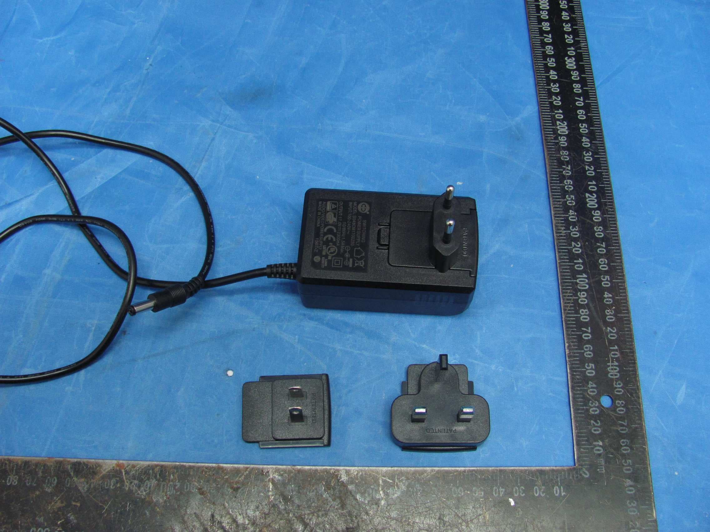
Click to zoom
Application Details
- Equipment Class
- DSS - Part 15 Spread Spectrum Transmitter
- Date of Grant
- May 19, 2015
- Application Purpose
- Original Equipment
- Date of Application
- May 18, 2015
- Equipment Note
- airstream s150
- Frequency Range
- 2402.00000000 - 2480.00000000
- Company
- MONITOR AUDIO LTD.
- Country
- United Kingdom
Documents & Files
Document Text
Text extracted from the exhibit documents filed with the FCC. Open a document above to read the original.
Users Manual
WARNING • TO PREVENT FIRE OR SHOCK HAZARD, DO NOT USE THIS PLUG WITH AN EXTENSION CORD, RECEPTACLE OR OTHER OUTLET UNLESS THE BLADES CAN BE FULLY INSERTED TO PREVENT BLADE EXPOSURE • TO PREVENT FIRE OR SHOCK HAZARD, DO NOT EXPOSE THIS APPLIANCE TO RAIN OR MOISTURE • TO PREVENT ELECTRIC SHOCK, MATCH WIDE BLADE PLUG TO WIDE SLOT AND FULLY INSERT. This lightning flash with an arrow head symbol, within an equilateral triangle, is intended to alert the user to the presence of un-insulated “dangerous voltage” within the product’s enclosure that may be of sufficient magnitude to constitute a risk of electric shock to the persons. Warning: To reduce the risk of electric shock, do not remove cover (or back), no user-serviceable parts inside. Refer servicing to qualified service personnel. This exclamation point within an equilateral triangle is intended to alert the user to presence of important maintenance (servicing) instructions in the literature accompanying the appliance. This is a “Class II”, “double insulated apparatus”. This apparatus must NOT have a safety connection to Earth. ENGLISH 1monitoraudio.com/airstream Important Safety Instructions 1. Read these instructions. 2. Keep these instructions. 3. Heed all warnings. 4. Follow all instructions. 5. Do not use this apparatus with water. 6. Clean only with a dry cloth. Great care and attention has gone into the materials chosen to produce the product. A gentle wipe with a dry, clean cloth is all that is required to remove any dust. Treat it as you would a fine piece of furniture because that is how they have been designed. 7. Do not block any ventilation openings. Install in accordance with Monitor Audio’s instructions. 8. Do not install near any heat source, such as radiators, heat registers, stoves, or other apparatus (including amplifiers) that produce heat. 9. Do not defeat the purpose of the polarised or grounding type plug. A polarised plug has two blades with one wider than the other. A grounding type plug has two blades and a third grounding prong. The wider blade or the third prong are provided for your safety. If the provided plug does not fit your outlet, consult an electrician for replacement of the obsolete outlet. 10. Protect the power cord from being walked on or pinched particularly at plugs, convenience receptacles, and the point where they exit from the apparatus. 11. Only use attachments/ accessories specified by Monitor Audio. 12. Use only with the cart, stand, tripod, bracket, or table specified by the manufacturer or sold with the apparatus. When a cart is used, use caution when moving the cart/ apparatus combination to avoid injury from tip-over. 13. Unplug this apparatus during lightening storms, or when unused for long periods of time. 14. Refer all servicing to qualified service personnel. Servicing is required when the apparatus has been damaged in any way, such as power supply cord or plug is damaged, liquid has been spilled or objects have fallen onto the apparatus, the apparatus has been exposed to rain or moisture, does not operate normally or has been dropped. 15. This apparatus shall not be exposed to dripping or splashing water and that no object filled with liquids such as vases shall be placed on the apparatus. 16. The appliance coupler is used as the disconnect device, the disconnect device shall remain readily operable. 17. This exclamation point within an equilateral triangle is intended to alert the user to the presence of important maintenance (servicing) instructions in the literature accompanying the appliance. 18. This product is not for use in an aeroplane. 19. Monitor Audio would discourage using its products in high humidity, extreme hot or cold or outdoor environments unless the product specifically advises suitability for such environments, for clarification of suitable products within the Monitor Audio range please contact a Monitor Audio representative Batteries NOTE: ONLY APPLIES TO PRODUCTS WITH REMOTE CONTROLS WARNING: DO NOT INGEST BATTERY, CHEMICAL BURN HAZARD. The remote control supplied with this product contains a coin/button cell battery. If the coin/button cell battery is swallowed it can cause severe internal burns in just 2 hours and can lead to death. Keep new and used batteries away from children. If the battery compartment does not close securely, stop using the product and keep it away from children. If you think batteries might have been swallowed or placed inside any part of the body, seek immediate medical attention. 1. WARNING: The battery (battery or batteries or battery pack) shall not be exposed to excessive heat such as sunshine, fire or the like 2. No naked flame sources, such as lighted candles, should be placed on the apparatus 3. Battery Warning. Technical Data 1. Temperature range from -5⁰C to 40°⁰C, humidity: 20% - 80%. 2. AC input voltage: 90V - 263V (Auto range). S300 ONLY Electrostatic Discharge In the event that the unit is subject to an electrostatic discharge, the unit may malfunction and require the user to reset the device in order to resume operation 2 Important Safety Instructions Re-cycling Correct Disposal of Waste Electrical and Electronic Equipment (WEEE) by User in Private Households in the EU. This symbol on the product or accessories indicates that they must not be disposed of with your household wastes throughout the EU. To prevent possible harm to the environment or human health from uncontrolled waste disposal, recycle it responsibly to promote the sustainable reuse of material resources. Instead it is your responsibility to dispose of your waste equipment by handing it over to a designated WEEE collection point for recycling. The separate collection and recycling of your waste equipment will help conserve natural resources and ensure that it is recycled in a manner that protects human health and the environment. For more specific information about where you can take your equipment for recycling please contact your local city/council office…
Text truncated - open the document above for the full version.
Users Manual
Page 1AIRSTREAM S150 S150 Instruction Manual DRAFT Page 2AIRSTREAM S150 Contents 1 Introduction .................................................................................................................................... 3 2 Electronic Specification Overview ................................................................................................... 3 2.1 PSU .......................................................................................................................................... 3 2.2 Power Amp section ................................................................................................................. 3 2.3 Other features ......................................................................................................................... 3 ARM Cortex M4 ........................................................................................................................... 3 3 Control ............................................................................................................................................ 3 3.1 Local Controls .......................................................................................................................... 3 3.2 Indicators and functionality .................................................................................................... 5 3.2.1 LED States ........................................................................................................................ 5 3.2.2 Functionality ................................................................................................................... 5 3.2.3 Button Controls ............................................................................................................... 5 4 Packaging ........................................................................................................................................ 5 4.1.1 Pack in accessories .......................................................................................................... 5 5 Specifications .................................................................................................................................. 6 This document is intended to be used as a reference for the supplier. It is designed to clearly communicate all the key design features and reasoning behind the design supplied. Note: This document contains confidential information that should not be distributed to third parties without prior consent from the Monitor Audio board of Directors. Page 3AIRSTREAM S150 1 Introduction A compact Bluetooth speaker system with Bluetooth only functionality. The acoustic system is based around a 3 amplifier platform driving 2 x full range drivers and 1 x 19mm tweeter. The functionality will be the same as other Airstream products and incorporate the same UI features. The unit will be mains powered. 2 Electronic Specification Overview 2.1 PSU The outboard PSU adaptor is auto‐ranging from mains input of 94‐264Vac (100‐240v nominal working voltage range) and with a minimum output of 17V/2300mA (40W) The PSU adaptor style will be designed to fit onto a wall socket and feature replaceable plug pins for; U.S.A, U.K, EU; 2.2 Power Amp section 3 x 20W @ 6Ω for drivers Class D amplifiers <1% THD+N (full power) 2.3 Other features ARM Cortex M4 aptX codec for Bluetooth 3 Control 3.1 Local Controls Localised controls should include: Volume up/down (side mounted) Power on/standby (front mounted) Auxiliary input button (side mounted) Bluetooth source button‐ using BT logo. (side mounted) Bluetooth pairing button (rear) Localised inputs and connections should include: 3.5mm mini‐jack (aux input) DC input by coaxial connector USB type A connector for generic 5v charging purposes (Apple charging?) – removed Apple authentication chip. Page 4AIRSTREAM S150 Figure 1. ‐ Airstream S150 Local Controls Figure 2. ‐ Airstream S150 Inputs and Connections POWER ON/ STANDBY VOLUME UP/DOWN BLUETOOTH SOURCE (BT STD LOGO) AUXILLIARY SOURCE (AUX LOGO) DC INPUT USB CHARGING (CHARGE LOGO) BT PAIRING (CONNECT LOGO FROM A100) 3.5MM MINI‐JACK (AUX LOGO) Page 5AIRSTREAM S150 3.2 Indicators and functionality 3.2.1 LED States 1. Solid Green – Auxiliary input 2. Flashing Cyan – Bluetooth searching 3. Solid Cyan – Bluetooth Paired/Connected 3.2.2 Functionality When the power button is pressed or the power lead is plugged in, the device will power on and initialise. The device will find and connect to the last BT paired device and then return to whichever source was last selected (if available). The user can then scroll through the available sources by pressing the source select button Bluetooth should remain connected to the BT device, even when in Aux mode. When playing a BT track and Aux is selected, the BT module should send a signal to the device to pause the track. 3.2.3 Button Controls Figure 3. – Side Button Controls 4 Packaging 4.1.1 Pack in accessories PSU adaptor + plug pins Quick Start Guide Safety Instructions POWER LED INDICATOR AUX SOURCE BUTTON VOLUME BLUETOOTH SOURCE BUTTON Page 6AIRSTREAM S150 5 Specifications S150 Frequency Response 80Hz - 20kHz Maximum SPL 94dB Power Output (RMS) Bass: 2 x 15 watts (<1% THD+N, 100Hz) Tweeter: 1 x 10 watts (<2% THD+N, 10,000Hz) Drive Unit Complement 2 x 3” (76mm) C-CAM® Cone Bass Driver 2 x 3/4” (19mm) C-CAM® Gold Dome Tweeter System Configuration 2 Way, Rear ABR Loading Auxiliary Input Impedance/ Sensitivity 10k Ohms/ 300mV Signal to Noise Ratio > 60dB DAC 28 - 56 Bit dual precision Input Voltage 100 - 240v for Power Adapter Amplifier Category Class D Power Consumption Standby: < 0.5W Rated: 70W Electrical Approvals ETL/ CE/ Fcc/CB/ ErP/ Wi-Fi/ Wi-Fi WMM/ Bluetooth/ Apple MFi Certified Dimensions (each) (H x W x D) 274 x 120 x 137mm (10 13/16 x 4 3/4 x 5 3/8 ”) Colour/ Finish Charcoal Grey with Black Grille Cloth White with Light Grey Grille Cloth Weight (each) 2.25Kg (…
Text truncated - open the document above for the full version.
External Photos
FCC ID: O7VMA191815 IC: 5928A-MA191815 Page 1 of 4 External Picture FCC ID: O7VMA191815 IC: 5928A-MA191815 Page 2 of 4 Adapter:AS600-170-AD230 FCC ID: O7VMA191815 IC: 5928A-MA191815 Page 3 of 4 Adapter:S048CM1700230 FCC ID: O7VMA191815 IC: 5928A-MA191815 Page 4 of 4 3 kinds of plug used for the two adaptor
ID Label/Location Info
label position
Internal Photos
FCC ID: O7VMA191815 IC: 5928A-MA191815 Page 1 of 7 Internal Picture FCC ID: O7VMA191815 IC: 5928A-MA191815 Page 2 of 7 PCB of Main Board FCC ID: O7VMA191815 IC: 5928A-MA191815 Page 3 of 7 PCB of controller FCC ID: O7VMA191815 IC: 5928A-MA191815 Page 4 of 7 PCB of port FCC ID: O7VMA191815 IC: 5928A-MA191815 Page 5 of 7 PCB of power key FCC ID: O7VMA191815 IC: 5928A-MA191815 Page 6 of 7 BT module FCC ID: O7VMA191815 IC: 5928A-MA191815 Page 7 of 7
RF Exposure Info
FCC ID: O7VMA191815 IC: 5928A-MA191815 Page 1 of 2 Statement of compliance to Maximum Permissible Exposure (MPE) Applicant : MONITOR AUDIO LTD. Unit 2, 24 Brook Road, Rayleigh, Essex SS6 7XJ England Manufacturer : MONITOR AUDIO LTD. Unit 2, 24 Brook Road, Rayleigh, Essex SS6 7XJ England Equipment : Wireless Speaker Type/Model : airstream s150 According to §2.1091, §2.1093 and §1.1307(b), systems operating under the provisions of this section shall be operated in a manner that ensures that the public is not exposed to radio frequency energy level in excess of the Commission’s guidelines. The S = PG / (4πR²) Where S = power density in mW/cm² P = transmit power in mW G = numeric gain of transmit antenna R = distance (cm) R is chosen to be 20cm, the gain of antenna G = 1.00dBi = 1.25 As we can see from the test reports 150300463SHA-001: The maximum output power for Bluetooth = 2.39dBm = 1.73mW S = PG / (4πR²) = 1.73 * 1.25 / (4 * 3.14 * 20 * 20) = 0.00043mW/cm² This level is below the simultaneous transmission MPE test exclusion requirements (≤1.0). Date of issue: Apr 27, 2015 Prepared by: Reviewed by: Jesse Xu (Project Engineer) Daniel Zhao (Reviewer) FCC ID: O7VMA191815 IC: 5928A-MA191815 Page 2 of 2 Appendix I Definition below must be outlined in the User Manual: To satisfy FCC RF exposure requirements, a separation distance of 20 cm or more should be maintained between the antenna of this device and persons during device operation. To ensure compliance, operations at closer than this distance is not recommended.
Test Report
FCC ID: O7VMA191815 IC: 5928A-MA191815 Page 1 of 56 EMC TEST REPORT for Intentional Radiator (BT Function) No. 150300463SHA-001 Applicant : Monitor Audio Ltd. Unit 2, 24 Brook Road, Rayleigh, Essex SS6 7XJ England Manufacturer : Monitor Audio Ltd. Unit 2, 24 Brook Road, Rayleigh, Essex SS6 7XJ England Equipment : Wireless Speaker Type/Model : airstream s150 SUMMARY The equipment complies with the requirements according to the following standard(s): 47CFR Part 15 (2014): Radio Frequency Devices ANSI C63.4 (2009): American National Standard for Methods of Measurement of Radio-Noise Emissions from Low-Voltage Electrical and Electronic Equipment in the Range of 9 kHz to 40 GHz RSS-210 Issue 8 (December 2010): Low-power Licence-exempt Radiocommunication Devices (All Frequency Bands): Category I Equipment RSS-Gen Issue 4 (November 2014): General Requirements and Information for the Certification of Radio communication Equipment Date of issue: Apr 27, 2015 Prepared by: Reviewed by: Jesse Xu (Project Engineer) Daniel Zhao (Reviewer) FCC ID: O7VMA191815 IC: 5928A-MA191815 Page 2 of 56 Description of Test Facility Name: Intertek Testing Services Ltd. Shanghai ETL Semko Address: Building No.86, 1198 Qinzhou Road(North), Shanghai 200233, P.R. China FCC Registration Number: 236597 IC Assigned Code: 2042B-1 Name of contact: Steve Li Tel: +86 21 64956565 ext. 214 Fax: +86 21 54262335 ext. 214 FCC ID: O7VMA191815 IC: 5928A-MA191815 Page 3 of 56 Content SUMMARY ....................................................................................................................................................... 1 DESCRIPTION OF TEST FACILITY ...................................................................................................................... 2 1. GENERAL INFORMATION ......................................................................................................................... 5 1.1 Applicant Information .................................................................................................. 5 1.2 Identification of the EUT ............................................................................................. 5 1.3 Technical specification ................................................................................................ 6 1.4 Mode of operation during the test / Test peripherals used ........................................... 6 2. TEST SPECIFICATION ............................................................................................................................... 7 2.1 Instrument list .............................................................................................................. 7 2.2 Test Standard ............................................................................................................... 7 2.3 Test Summary .............................................................................................................. 8 3. 20 DB BANDWIDTH ................................................................................................................................... 9 3.1 Limit ............................................................................................................................. 9 3.2 Test Configuration ....................................................................................................... 9 3.3 Test Procedure and test setup ....................................................................................... 9 3.4 Test Protocol .............................................................................................................. 10 4. CARRIER FREQUENCY SEPARATION ..................................................................................................... 12 4.1 Limit ........................................................................................................................... 12 4.2 Test Configuration ..................................................................................................... 12 4.3 Test Procedure and test setup ..................................................................................... 12 4.4 Test Protocol .............................................................................................................. 13 5. MAXIMUM PEAK OUTPUT POWER .......................................................................................................... 15 5.1 Test limit .................................................................................................................... 15 5.2 Test Configuration ..................................................................................................... 15 5.3 Test procedure and test setup ..................................................................................... 15 5.4 Test protocol .............................................................................................................. 16 6.0 RADIATED SPURIOUS EMISSIONS .............................................................................................................. 22 6.1 Test limit .................................................................................................................... 22 6.2 Test Configuration ..................................................................................................... 22 6.3 Test procedure and test setup ..................................................................................... 23 6.4 Test protocol .............................................................................................................. 25 7.CONDUCTED SPURIOUS EMISSIONS & BAND EDGE ..................................................................................... 27 7.1 Limit ........................................................................................................................... 27 7.2 Test Configuration ...................................................................................................…
Text truncated - open the document above for the full version.
Test Setup Photos
FCC ID: O7VMA191815 IC: 5928A-MA191815 Page 1 of 3 Test Setup FCC ID: O7VMA191815 IC: 5928A-MA191815 Page 2 of 3 1. Radiated Emission FCC ID: O7VMA191815 IC: 5928A-MA191815 Page 3 of 3 2. Conducted Emission
Contact Information
Applicant
Thomas Fall(Quality Manager)
Technical Contact
Intertek Testing Services Limited ShanghaiJesse Xu
[email protected]86-21-61215147
Building No.86, 1198 Qinzhou Road(North) · Shanghai · China
Test Firm
Intertek Testing Services Limited ShanghaiJonny Jing
Technical Specifications
| # | Rule Parts | Frequency Range | Power Output |
|---|---|---|---|
| 1 | 15C | 2.40 GHz - 2.48 GHz | 1.73 mW |
Other Applications from MONITOR AUDIO LTD.

O7V-MA104210
Jan 21, 2026Caspian 4G Streaming Amplifier / Integrated Amplifier
Equipment Class
DSS - Part 15 Spread Spectrum TransmitterO7VMA120201
Jul 12, 2021Amplifier
Equipment Class
DTS - Digital Transmission System
O7VMA232015
Jan 21, 2015Wireless Transmitter
Equipment Class
DXX - Part 15 Low Power Communication Device Transmitter
O7VMA191522
Aug 11, 2013ASB-2
Equipment Class
DTS - Digital Transmission System
O7VMA191811
Mar 10, 2013Audio Amplifier
Equipment Class
DTS - Digital Transmission System