O7X-562188Wireless Video Game Controller
Pelican Accessories
Click to zoom
Application Details
- Equipment Class
- DXX - Part 15 Low Power Communication Device Transmitter
- Date of Grant
- Nov 02, 2000
- Application Purpose
- Original Equipment
- Date of Application
- Nov 02, 2000
- Equipment Note
- Wireless Video Game Controller
- Frequency Range
- 916.50000000 - 916.50000000
- Company
- Pelican Accessories
- Country
- United States
Documents & Files
Document Text
Text extracted from the exhibit documents filed with the FCC. Open a document above to read the original.
Users Manual
Instructions for operation 1. Install the 4 AAA batteries (enclosed). Make sure to insert batteries properly as illustrated in the battery compartment. Always use high quality long lasting alkaline batteries. 2. Make sure Playstation® 2 is turned off. Install receiver into Playstation® 2 console. The antennas on the Receiver are to improve reception. Make sure they are separated and pointing down and slightly forward. 3. Power-on Freedom Shock 2 by pressing the Power Button - a green LED will illuminate. Note: Power Button only powers-on Freedom Shock 2. 4.Freedom Shock 2 will shut down automatically after 5 minutes of non use. 5. To increase battery life you may choose to turn off vibration motors. You may do this by pressing Select and Start at the same time, repeat procedure to turn Freedom Shock 2 back on. 6. You are now ready to use your Freedom Shock 2. . Operating Two Freedom Shock 2 Controllers Simultaneously 1. Make sure you have purchased one Channel A frequency Freedom Shock 2 and one Channel B Freedom Shock 2. This is indicated on the security tape of the packaging as well as on the bottom of each controller. 2. Link Channel A receiver to Channel B receiver with the link cable found in the Channel B Freedom Shock 2. 3. You are ready to play. Programmable Functions: 1. Press the program key, the yellow LED lights up. Touch the button to be programmed, the LED flashes, then press the button you would like to relocate and the LED will turn off. (For example, if you would like to relocate the X button function to the button, you would hit Program, then X. Now the X button function is controlled by the button.) LEDs: Pressing the mode button activates Digital and Analog Mode. Red LED indicates Analog Mod Green LED indicates Digital Yellow LED indicates Program Mode Changes or modifications not expressly approved by the manufacture could void the user's authority to operate the equipment. This device complies with Part 15 of the FCC Rules. Operation is subject to the following two conditions: (1) this device may not cause harmful interference, and (2) this device must accept any interference received, including interference that may cause undesired operation.
Cover Letter(s)
Request for Confidentiality 8-14-00 American Telecommunications Certification Body, Inc 6731 Whittier Avenue Suite C110 Mclean, VA 22101 RE: Certification Application For Freedom Shock 2 Controller FCC ID # O7X-562188 Please be advised that the following information is to be held confidential and behalf of Pelican Accessories. • Schematics • Block diagram • Theory of Operation The application contains technical information which Pelican Accessories deems to be trade secrets and proprietary. If made public, the information might be used to the disadvantage of the applicant in the market place. Thanks for you attention to this matter. Jason Biheller Product Manager Pelican Accessories 1840 East 27 th Street Vernon, Ca 90058
External Photos
EUT Top EUT Bottom Battery Cover Removed
ID Label/Location Info
FCC ID LABEL LOCATION
ID Label/Location Info
FCC Label for the Freedom Shock 2 Controller Unit (Not Shown At Actual Size)
ID Label/Location Info
FCC ID LABEL LOCATION
Internal Photos
Internal View Top Internal View Bottom PCB Top View PCB Bottom View
Test Report
FCC CERTIFICATION TEST REPORT for Pelican Accessories 1840 East 27 th Street Vernon, CA 90058 FCC ID: O7X-562188 October 5, 2000 WLL PROJECT #: 6031X This report may not be reproduced, except in full, without the prior written consent of Washington Laboratories, Ltd. Pelican Accessories FCC ID:O7X-562188 WLL Project #:6031X i TABLE OF CONTENTS Statement of Qualifications 1.0 INTRODUCTION...........................................................................................................................................................1 1.1 SUMMARY......................................................................................................................................................................1 2.0 DESCRIPTION OF EQUIPMENT UNDER TEST (EUT).................................................................1 2.1 ON-BOARD OSCILLATORS...........................................................................................................................................1 3.0 TEST CONFIGURATION............................................................................................................................................2 3.1 TESTING ALGORITHM.................................................................................................................................................2 3.2 CONDUCTED EMISSIONS TESTING...........................................................................................................................2 3.3 RADIATED EMISSIONS TESTING...............................................................................................................................2 3.3.1 Radiated Data Reduction and Reporting........................................................................................................3 Tables Table 1. Radiated Emissions Results Table 2. System Under Test Table 3. Interface Cables Used Table 4. Measurement Equipment Used Appendices Appendix A. Statement of Measurement Uncertainty Pelican Accessories FCC ID:O7X-562188 WLL Project #:6031X ii STATEMENT OF QUALIFICATIONS for Steven Koster Washington Laboratories, Ltd. I am a NARTE-Accredited EMC Test Laboratory Engineer with over nineteen years of electronics experience, the last ten years being directly involved in EMI testing. I am qualified to perform EMC testing to the methods described in this test report. The measurements taken within this report are accurate within my ability to perform the tests and within the tolerance of the measuring instrumentation. By: _______________________ Steven Koster Compliance Engineer Date: October 5, 2000 Pelican Accessories FCC ID:O7X-562188 WLL Project #:6031X 1 FCC CERTIFICATION TEST REPORT for FCC ID: O7X-562188 1.0 Introduction This report has been prepared on behalf of Pelican Accessories to support the attached Application for Equipment Authorization. The test and application are submitted for a Intentional Radiator under Part 15.249 of the FCC Rules and Regulations. The Equipment Under Test was the Freedom Shock 2 Pad Controller. All measurements herein were performed according to the 1992 version of ANSI C63.4. The measurement equipment conforms to ANSI C63.2 Specifications for Electromagnetic Noise and field Strength Instrumentation. Calibration checks are made periodically to verify proper performance of the measuring instrumentation. All measurements are performed at Washington Laboratories, Ltd. test center in Gaithersburg, MD. Site description and site attenuation data have been placed on file with the FCC's Sampling and Measurements Branch at the FCC laboratory in Columbia, MD. Washington Laboratories, Ltd. has been accepted by the FCC and approved by NIST NVLAP (NVLAP Lab Code: 200066-0) as an independent FCC test laboratory. All results reported herein relate only to the equipment tested. The measurement uncertainty of the data contained herein is ±2.3 dB. Refer to Appendix A for Statement of Measurement Uncertainty. This report shall not be used to claim product endorsement by NVLAP or any agency of the US Government. 1.1 Summary The Pelican Accessories Freedom Shock 2 Pad Controller complies with the limits for a Intentional Radiator under Part 15.249 of the FCC Rules and Regulations. 2.0 Description of Equipment Under Test (EUT) The Pelican Accessories Freedom Shock 2 Pad Controller (EUT) is a 900 MHz Wireless RF Controller used to replace existing hard-wired video game system controllers. Upon activation of the game the Base Interface/Dongle unit (Separate certification, FCC ID: O7X-569888) transmits a “ping” to the hand-held pad controller using OOK On-Off Keying at 916.5 MHz. The controller pad then transmits data to the Interface/Dongle for game control. The EUT is powered via 4 AAA batteries. A future addition to the EUT will use a transmit frequency of 926 MHz so that two controllers may be used simultaneously, however, this application only covers the EUT operation of 916.5 MHz. 2.1 On-board Oscillators The Pelican Accessories Freedom Shock 2 Pad Controller contains the following oscillators: 14.3203125 MHz, 7.124 MHz, 14.31818 MHz. Pelican Accessories FCC ID:O7X-562188 WLL Project #:6031X 2 3.0 Test Configuration To complete the test configuration required by the FCC, the transmitter was tested in all three orthogonal planes. All testing was performed at 6VDC. 3.1 Testing Algorithm The transmitter was turned on and constantly transmitting. The unit was used in conjunction with a video game system to verify operation. Worst case emissions are recorded in the data tables. 3.2 Conducted Emissions Testing The Freedom Shock 2 pad controller is battery-powered, therefore no conducted emissions testing was performed. 3.3 Radiated Emissions Testing The EUT was placed on an 80 cm high 1 x 1.5 meters non-conductive motorized turntable for radiated testing on a 3- meter open field test site. The emissions from the EUT were measured continuously at every azimuth by rotating the turntable. Biconical and log…
Text truncated - open the document above for the full version.
Test Report
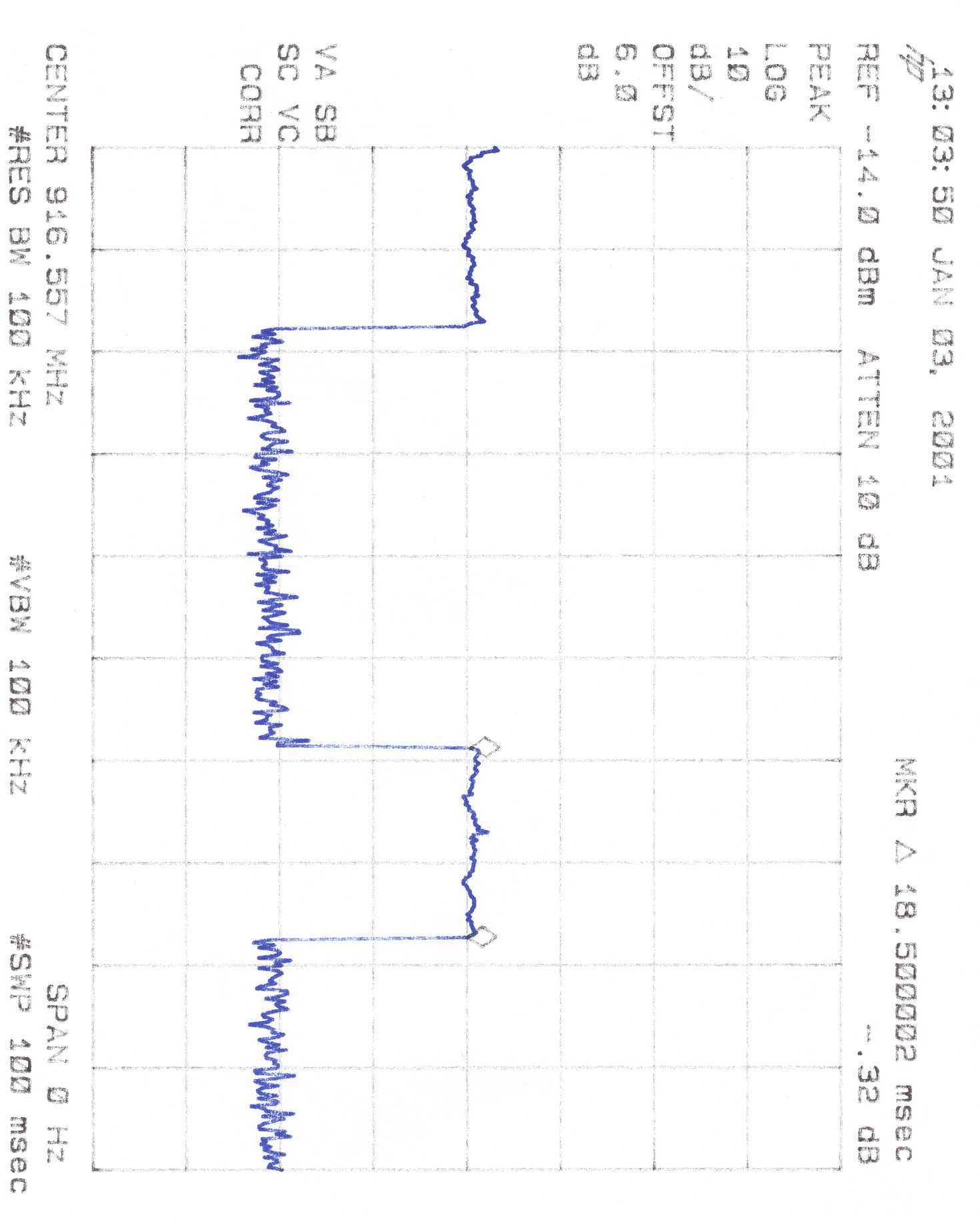
DUTY CYCLE CALCULATIONS For: Pelican Accessories, FCC ID: O7X-562188 The following calculations show the worst case 100 ms duty cycle correction used for calculating the average level of the harmonic emissions. The worst case coding has a pulse width of 18.5 ms on time. ON TIME PER 100 ms: 18.5 ms x 2 = 37 ms ON TIME PER 100 ms = 37% DUTY CYCLE = -8.64 dB FCC 3M PART 15.247 RADIATED EMISSIONS DATA - SITE 2 Average Emissions Data CLIENT:Pelican Accessories MODEL NO:Freedom Shock 2 Controller Pad DATE:10/5/2000 BY:Steve Koster JOB #:6031x Tx Frequency:916.59MHz Freque ncyPolarityAzimuthAntSA LevelAfdAFcE-FieldE-FieldLi mi tMargi n HeightPeak MHzH/VDegreemdBuVdBdB/mdBuV/muV/muV/mdB 1833.00V135.001.062.7-8.6-7.047.1226.2500.0-6.9 1833.00H0.001.068.1-8.6-7.052.5421.2500.0-1.5 2749.39H202.501.065.2-8.6-4.851.8387.4500.0-2.2 2749.39V0.001.065.2-8.6-4.851.8387.4500.0-2.2 3665.71V0.001.063.2-8.6-3.751.0353.6500.0-3.0 3665.71H180.001.063.4-8.6-3.751.1361.0500.0-2.8 4582.21V135.001.052.2-8.6-2.740.9110.7500.0-13.1 4582.21H0.001.055.3-8.6-2.744.0158.0500.0-10.0 5498.67V0.001.047.1-8.6-2.036.567.0500.0-17.5Ambient 6415.26V0.001.047.0-8.60.138.583.8500.0-15.5Ambient 7331.67V0.001.044.9-8.62.238.584.1500.0-15.5Ambient 8248.17V0.001.045.3-8.62.238.988.1500.0-15.1Ambient 9165.00V0.001.045.7-8.62.439.594.5500.0-14.5Ambient
Contact Information
Applicant
Shilo Dean Prychak(Director of Product)
Technical Contact
Washington Laboratories, Ltd.Gregory M Snyder
[email protected]301 417 0220
7560 Lindbergh Drive · Gaithersburg, Maryland · United States
Non-Technical Contact
Washington Laboratories, Ltd.Brian J Detting
[email protected]301 417 0220
Test Firm
Washington Laboratories, Ltd.Michael Violette
Technical Specifications
| # | Rule Parts | Frequency Range | Power Output |
|---|---|---|---|
| 1 | 15C | 916.5 MHz - 916.5 MHz | - |
Other Applications from Pelican Accessories

O7X-NERFPS2-01
Nov 05, 2006Wireless Controller
Equipment Class
DXX - Part 15 Low Power Communication Device Transmitter
O7X-PRED-S1
Sep 05, 2005Wireless Game Controller
Equipment Class
DXX - Part 15 Low Power Communication Device Transmitter
O7X-PRED-S2
Sep 05, 2005Wireless Game Controller Dongle
Equipment Class
DXX - Part 15 Low Power Communication Device Transmitter
O7X-BLDS01
Jul 04, 2005X-Box Wireless Controller
Equipment Class
DXT - Part 15 Low Power Transceiver, Rx Verified
O7X-BLDS02
Jul 04, 2005X-Box Transmitter/Receiver Dongle
Equipment Class
DXT - Part 15 Low Power Transceiver, Rx Verified