O7X-G3-2G3 Wireless Controller
Pelican Accessories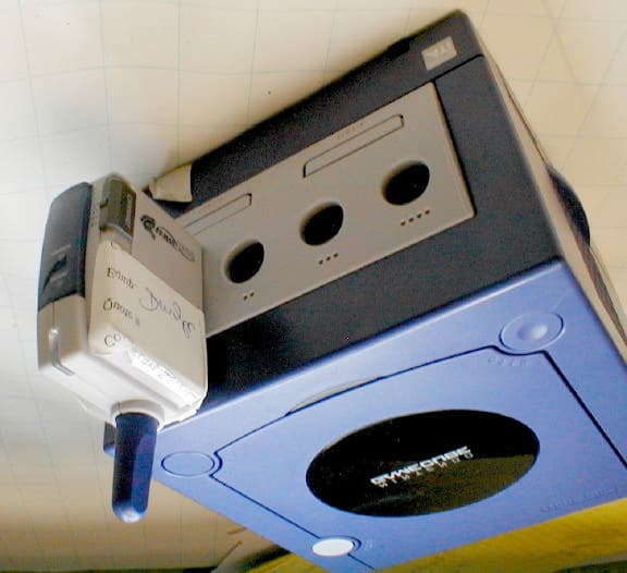
Click to zoom
Application Details
- Equipment Class
- DXT - Part 15 Low Power Transceiver, Rx Verified
- Date of Grant
- Feb 11, 2003
- Application Purpose
- Original Equipment
- Date of Application
- Feb 11, 2003
- Equipment Note
- G3 Wireless Controller
- Frequency Range
- 903.00000000 - 926.50000000
- Company
- Pelican Accessories
- Country
- United States
Documents & Files
Document Text
Text extracted from the exhibit documents filed with the FCC. Open a document above to read the original.
Users Manual
Instruction for Operation: Wireless with Rumble LIMITED WARRANTY Pelican Accessories warrants to the original consumer purchaser that the product will be free from defects in materials and / or workmanship for a period of 120 days from the date of purchase. If a defect covered by this warranty occurs during this period, Pelican Accessories at its option will repair or replace, at no charge, any part that Pelican Accessories determines to be defective. To obtain warranty service during the warranty period, send the defective product postage pre-paid, with a money order for $4.00 to cover the return postage and handling, along with proof of purchase and the date of purchase to: PELICAN ACCESSORIES 1840 East 27th Street Vernon, CA 90058 This warranty shall not apply if the product has been damaged by abuse, misuses, negligence, accident, modification, tampering or by any other causes unrelated to defective materials and / or workmanship. Repair or replacement as provided under this warranty is Pelican Accessories' exclusive prerogative. ANY APPLICABLE IMPLIED WARRANTIES, INCLUDING WARRANTIES OR MERCHANTABILITY AND FITNESS FOR A PARTICULAR PURPOSE ARE HERBY LIMITED TO 120 DAYS FROM THE DATE OF PURCHASE AN ARE SUBJECT TO THE CONDITIONS SET FORTH IN THIS LIMITED WARRANTY. IN NO EVENT SHALL PELICAN ACCESSORIES OR INCIDENTAL DAMAGES RESULT FROM THE BREACH OF ANY EXPRESS OR IMPLIED WARRANTIES. This warranty gives you specific legal rights, and you may also have other legal rights, Which vary from state to state. Pelican and its logo are registered trademarks. GameCube™ is a registered trademark of Nintendo of America, Inc. This product is not desgined, manufactured, sponsored or endorsed by Nintendo of America, Inc. Instruction for Operation: PL-7008 Wireless with Rumble Our products are developed, tested, and approved by gamers for gamers. Pelican’s Gamer’s Guarantee states: If you are not 100% satisfied with your new G3 Wireless controller we will replace it or replace it with an equal valued item. SIGNAL CHANNEL 1 2 3 4 OFF ON RUMBLE START / PAUSE OFF RL 4 3 2 1 SIGNAL POWER B A BAND Left & Right Triggers Turbo Button Analog Stick D-Pad Power On/Off-rumble Off Switch A/B Band Switch Channel Switch Action Buttons Signal LED (Yellow) Start/ Pause Analog Stick A B BAND Link LED (Green) Signal LED (Yellow) Power LED (Red) Channel Switch Band Switch PRODUCT OVERVIEW: G3 Wireless Controller uses advance technology which gives you the ability to play without the limitations of a typical corded controller, hence there are a few switches and LED (lights) not found on your basic GameCube™ Controller. Channel Switch (Receiver and Controller): This switch selects the broadcast channel of the radio frequency. There are four positions; 1, 2, 3 and 4. There is a corresponding Channel Switch on the receiver Band Switch (Receiver and Controller): This switch selects the bandwidth. There are two positions; A and B. There is a corresponding Band Switch on the receiver Power Switch (Controller): This switch selects the power mode. There are 3 positions; Off, On, and Rumble Off Signal LED (Yellow, Receiver and Controller): When on or flickering data is being transmitted between Controller and Receiver Power LED (Red, Receiver): When on indicates Receiver is operating correctly Link LED (Green, Receiver): When on indicates Controller and Receiver are linked and communicating. If flickering the Controller and Receiver are not communicating INSTRUCTIONS: 1. Insert Batteries: Remove the battery lid and place the two AA batteries (included) into the G3 Wireless Controller. Make sure they are inserted as shown in the battery compartment. The batteries included are not long life. 2. Plug in the Receiver: With the GameCube™ turned off, plug the receiver into controller port one (far left port.) 3. Check Band setting: Confirm that the Band Switch is set to A on both the controller and the receiver. Note:the only time you would ever change this switch is if you experienced a drop off in the signal, causing game play to be suspended. If this happens repeatedly we suggest you switch to Band B on both the Controller and Receiver. 4. Select a Channel on the Controller: You may select any channel you desire 1, 2, 3 or 4. 5. Select a Channel on the Receiver: This must match the channel selected on the Controller. Note:If using more then one controller you must use different channel settings, i.e., the first controller and receiver are set to Channel 1, the second controller and receiver are set to Channel 2. The channel position selected on the G3 Controller and Receiver have no relation to the GameCube™ controller ports. 6. Turn on the Controller: Move the Power Switch to On, the signal LED will light. Note:If you wish to extend battery life select the Rumble Off position. This will turn off the rumble effect in game play resulting in a doubling of your battery life. OTHER FEATURES: Multiple Players: You may play with up to four G3 Wireless controllers. Check to see that the channel switches are set as outlined above. Power Save Mode: When not in use the G3 controller automatically goes into a sleep mode to conserve batteries. A touch of any button puts the controller back into play mode. Note: Turn off the controller when not in use to extend your battery life. Turbo Function: This feature allows rapid fire of any selected fire button. To turn on, press the Turbo button, and then while still holding down the Turbo button press the fire button that you wish to have the Turbo feature. To return the button back to a normal fire button repeat the above process or turn on and off the controller. For technical questions please visit http://www.pelicanacc.com or call us directly at 1-800-331-3844 Gamer’s Guarantee Changes or modifications not expressly approved by the manufacture could void the user's authority to operate the equipment. This device complies with Part 15 of the FCC Rules. Operation is subject to the following two condi…
Text truncated - open the document above for the full version.
Block Diagram
ANT Block Diagram K9993H Cube RF Host Digital Driven Solutions Revision 4 February 2003 PORT CONTROL IC RF CONTROL IC CHANNEL SELECTION 14.7456MHz Crystal RF IN/OUT INTERNAL - LOW FREQUENCY I.F. STAGE (150kHz) DEMOD MIXER VCO DATA & CONTROL ANT TRANSCEIVER MODULE CONSOLE INTERFACE Notes: RF IN/OUT consists of a 24mm PCB design antenna and a 44mm WHIP antenna evenly coiled to a internal diameter of 2mm, and a height of 35mm. Crystal Locked PLL Superheterodyne design PROGRAMMABLE SYNTHESIZER CH1 Tuning Range = 902.978MHz - 903.022MHz TX Freq: 903-926.5MHz RX Freq: 903.15-926.65MHz TX VCO Freq: 903-926.5MHz RX VCO Freq: 903.15-926.65MHz PA LNA CONTROL
Cover Letter(s)
Request for Confidentiality 12-14-02 American Telecommunications Certification Body, Inc 6731 Whittier Avenue Suite C110 Mclean, VA 22101 RE: Certification Application For GameCube PL-7008 FCC ID # 07X-G3-2 Please be advised that the following information is to be held confidential and behalf of Pelican Accessories. • Schematics • BOM information • Theory of Operation The application contains technical information which Pelican Accessories deems to be trade secrets and proprietary. If made public, the information might be used to the disadvantage of the applicant in the market place. Thanks for you attention to this matter. Jason Biheller Product Manager Pelican Accessories 1840 East 27 th Street Vernon, Ca 90058
Cover Letter(s)
American Telecommunications Certification Body Inc. 6731 Whittier Ave, McLean, VA 22101 January 22, 2003 RE: FCC ID: O7X-G3-2 Attention: Gregory M. Snyder / Brian J. Dettling I have a few comments on this Application. 1. Please note that 2.1033(b) (5) states, “A block diagram showing the frequency of all oscillators in the device. The signal path and frequency shall be indicated at each block. The tuning range(s) and intermediate frequency(ies) shall be indicated at each block.” Please note that the block diagram provided does not meet this requirement. Please provide a block diagram meeting the requirements of 2.1033(b)(5). 2. The photo of the FCC ID location is not clear. The ID number cannot be clearly identified. Please provide a photo clearly showing the FCC ID. 3. Please note that there appears to be more than ample room on the device to have the 15.21 2 condition statement. Please also note that the FCC only allows certain exceptions to this requirement. This device does not appear to meet any of these exceptions. Please evidence that the 2 condition statement required by 15.21 will be placed on the device and please provide a photo or drawing showing where this label will be placed. 4. Please note, your request for confidentiality only covers the schematics and theory of operation. It does not cover the parts list. Typically parts lists are not required for part 15 devices. If this parts list is uploaded to the FCC website, it will not be considered confidential until and unless the request for confidentiality is rewritten to include the parts list exhibit. 5. The EUT also appears to be a Class B digital device. As such the manual is required to have the information to the user as defined in 15.105(b). Please revise the manual to include this statement. Alternately, please explain how this is not a Class B digital device. 6. What steps were taken to determine that “rumble data’ was the worse case? 7. In table 3 you state that the bandwidth of the system at the various test frequencies is greater than 175MHz. The plot says 175kHz. Please correct the table 3 to agree with the plotted data. Dennis Ward mailto:[email protected] The items indicated above must be submitted before processing can continue on the above referenced application. Failure to provide the requested information may result in application termination. Correspondence should be considered part of the permanent submission and may be viewed from the Internet after a Grant of Equipment Authorization is issued. Please do not respond to this correspondence using the email reply button. In order for your response to be processed expeditiously, you must submit your documents through the AmericanTCB.com website. Also, please note that partial responses increase processing time and should not be submitted. Any questions about the content of this correspondence should be directed to the sender.
Cover Letter(s)
Response to ATCB Comments FCC ID: O7X-G3-2 1 Washington Laboratories, Ltd. 7560 LINDBERGH DRIVE GAITHERSBURG, MD 20879 (301) 417 – 0220 FAX # (301) 417 - 9069 February 10, 2003 Mr. Dennis Ward American Telecommunications Certification Body Inc. 6731 Whittier Ave McLean, VA 22101 RE: Comments of January 22, 2003 APPLICATION: O7X-G3-2 Pelican Accessories Dear Mr. Johnson: Below are the comments that you have provided regarding the application for certification referenced above. Our responses to those comments are in bold italic. Many responses refer you to additional exhibit(s) which has been uploaded to the application folder at the ATCB website. Thank you for your attention. Please feel free to contact us for any additional information that you may require. Regards, Gregory M. Snyder Chief EMC Engineer, Wireless/Telco Services Manager Brian J. Dettling Documentation Specialist WLL Project: 7294 January 22, 2003 RE: Pelican Accessories FCC ID: O7X-G3-2 1) Please note that 2.1033(b) (5) states, “A block diagram showing the frequency of all oscillators in the device. The signal path and frequency shall be indicated at each block. The tuning range(s) and intermediate frequency(ies) shall be indicated at each block.” Please note that the block diagram provided does not meet this requirement. Please provide a block diagram meeting the requirements of 2.1033(b)(5). Response to ATCB Comments FCC ID: O7X-G3-2 2 R. Please see exhibit “G3-2 Block Diagram-Rev4.pdf”. 2) The photo of the FCC ID location is not clear. The ID number cannot be clearly identified. Please provide a photo clearly showing the FCC ID. R. Please see exhibit “G3-2 Label Moulding 1.pdf.” 3) Please note that there appears to be more than ample room on the device to have the 15.21 2 condition statement. Please also note that the FCC only allows certain exceptions to this requirement. This device does not appear to meet any of these exceptions. Please evidence that the 2 condition statement required by 15.21 will be placed on the device and please provide a photo or drawing showing where this label will be placed. R. As this unit is similar to previous “hosts” that have been approved and the device is smaller than the palm of the hand, the statement required by 15.19 and 15.21 have been included in the User’s Guide. 4) Please note, your request for confidentiality only covers the schematics and theory of operation. It does not cover the parts list. Typically parts lists are not required for part 15 devices. If this parts list is uploaded to the FCC website, it will not be considered confidential until and unless the request for confidentiality is rewritten to include the parts list exhibit. R. A corrected Request For Confidentiality letter has been uploaded. Please see exhibit “G3-2 Revised RFC Letter.pdf”. 5) The EUT also appears to be a Class B digital device. As such the manual is required to have the information to the user as defined in 15.105(b). Please revise the manual to include this statement. Alternately, please explain how this is not a Class B digital device. R. As required for the certification, the statement of 15.19(3) has been included in the User’s Manual to warn the user of interference. Previous devices of this nature have not required the additional statement of 15.105, however, the client has been notified to add this statement to future manuals. 6) What steps were taken to determine that “rumble data’ was the worse case? R. The “rumble data” is the only data transmitted by the device. 7) In table 3 you state that the bandwidth of the system at the various test frequencies is greater than 175MHz. The plot says 175kHz. Please correct the table 3 to agree with the plotted data. R. Table 3 of the Test Report has been corrected. Please see exhibit “G3-2 Test Report Revision 1.pdf.”
External Photos
Dongle in use Front Back Side Side Bottom
Internal Photos
Disassembled Side A Side B No additional components or traces underneath
Test Report
Document 7294-01, Rev. 1 FCC ID: 07X-G3-2 FCC Certification Test Report Washington Laboratories, Ltd January 2003 FCC Certification Test Report for Pelican Accessories O7X-G3-2 January 30, 2003 Prepared for: Pelican Accessories 1840 East 27th Street Vernon, CA 90058 Prepared By: Washington Laboratories, Ltd. 7560 Lindbergh Drive Gaithersburg, Maryland 20879 FCC Certification Test Report Document 7294-01, Rev. 1 FCC ID: 07X-G3-2 FCC Certification Test Report Washington Laboratories, Ltd January 2003 FCC Certification Test Program FCC Certification Test Report for the Pelican Accessories K9993H (PL-7008) Nintendo® Game Cube™ Wireless Controller Host (“Dongle”) O7X-G3-2 January 30, 2003 WLL JOB# 7294 Prepared by: Brian J. Dettling Documentation Specialist Reviewed by: Gregory M. Snyder Wireless/Telco Services Manager & Chief EMC Engineer Document 7294-01, Rev. 1 FCC ID: 07X-G3-2 FCC Certification Test Report Washington Laboratories, Ltd January 2003 ii Abstract This report has been prepared on behalf of Pelican Accessories to support the attached Application for Equipment Authorization. The test report and application are submitted for a Intentional Radiator under Part 15.249 of the FCC Rules and Regulations. This Federal Communication Commission (FCC) Certification Test Report documents the test configuration and test results for a Pelican Accessories K9993H (PL-7008) Nintendo® Game Cube™ Wireless Controller Host (“Dongle”). Testing was performed on an Open Area Test Site (OATS) of Washington Laboratories, Ltd, 7560 Lindbergh Drive, Gaithersburg, MD 20879. Site description and site attenuation data have been placed on file with the FCC's Sampling and Measurements Branch at the FCC laboratory in Columbia, MD. Washington Laboratories, Ltd. has been accepted by the FCC and approved by NIST NVLAP (NVLAP Lab Code: 200066-0) as an independent FCC test laboratory. The Pelican Accessories K9993H (PL-7008) Nintendo® Game Cube™ Wireless Controller Host (“Dongle”) complies with the limits for a Intentional Radiator device under Part 15.249 of the FCC Rules and Regulations. Document 7294-01, Rev. 1 FCC ID: 07X-G3-2 FCC Certification Test Report Washington Laboratories, Ltd January 2003 iii Table of Contents Abstract......................................................................................................ii 1 Introduction...................................................................................................................1 1.1 Compliance Statement............................................................................................1 1.2 Test Scope............................................................................................................1 1.3 Contract Information..............................................................................................1 1.4 Test Dates.............................................................................................................1 1.5 Test and Support Personnel....................................................................................1 1.6 Abbreviations.........................................................................................................2 2 Equipment Under Test....................................................................................................3 2.1 EUT Identification & Description............................................................................3 2.2 Test Configuration..................................................................................................3 2.3 Testing Algorithm...................................................................................................4 2.4 Test Location.........................................................................................................4 2.5 References.............................................................................................................4 2.6 Measurement Uncertainty.......................................................................................4 3 Test Equipment..............................................................................................................5 4 Test Results...................................................................................................................6 4.1 Duty Cycle Correction...........................................................................................6 4.2 Occupied Bandwidth: (FCC Part §2.1049)............................................................9 4.3 Radiated Spurious Emissions: (FCC Part §2.1053)...............................................13 4.3.1 Test Procedure..........................................................................................13 4.4 Conducted Emissions (AC Power Line)................................................................20 Document 7294-01, Rev. 1 FCC ID: 07X-G3-2 FCC Certification Test Report Washington Laboratories, Ltd January 2003 iv List of Tables Table 1. Device Summary....................................................................................................3 Table 2: Test Equipment List...............................................................................................5 Table 3. Occupied Bandwidth Results................................................................................13 Table 4. Radiated Emissions Limits.....................................................................................13 Table 5: Radiated Emissions Test Data..............................................................................15 Table 6. Radiated Emission Data, Average Data Above 1GHz............................................16 Table 7. Radiated Emission Data, Peak Data Above 1GHz.................................................18 Table 8: AC Power Line Conducted Emissions Test Data Sheet..................................21 List of Figures Figure 1. Duty Cycle Plot – Pulse Width..................................................…
Text truncated - open the document above for the full version.
Test Setup Photos
Instruction for Operation: Wireless with Rumble LIMITED WARRANTY Pelican Accessories warrants to the original consumer purchaser that the product will be free from defects in materials and / or workmanship for a period of 120 days from the date of purchase. If a defect covered by this warranty occurs during this period, Pelican Accessories at its option will repair or replace, at no charge, any part that Pelican Accessories determines to be defective. To obtain warranty service during the warranty period, send the defective product postage pre-paid, with a money order for $4.00 to cover the return postage and handling, along with proof of purchase and the date of purchase to: PELICAN ACCESSORIES 1840 East 27th Street Vernon, CA 90058 This warranty shall not apply if the product has been damaged by abuse, misuses, negligence, accident, modification, tampering or by any other causes unrelated to defective materials and / or workmanship. Repair or replacement as provided under this warranty is Pelican Accessories' exclusive prerogative. ANY APPLICABLE IMPLIED WARRANTIES, INCLUDING WARRANTIES OR MERCHANTABILITY AND FITNESS FOR A PARTICULAR PURPOSE ARE HERBY LIMITED TO 120 DAYS FROM THE DATE OF PURCHASE AN ARE SUBJECT TO THE CONDITIONS SET FORTH IN THIS LIMITED WARRANTY. IN NO EVENT SHALL PELICAN ACCESSORIES OR INCIDENTAL DAMAGES RESULT FROM THE BREACH OF ANY EXPRESS OR IMPLIED WARRANTIES. This warranty gives you specific legal rights, and you may also have other legal rights, Which vary from state to state. Pelican and its logo are registered trademarks. GameCube™ is a registered trademark of Nintendo of America, Inc. This product is not desgined, manufactured, sponsored or endorsed by Nintendo of America, Inc. Instruction for Operation: PL-7008 Wireless with Rumble Our products are developed, tested, and approved by gamers for gamers. Pelican’s Gamer’s Guarantee states: If you are not 100% satisfied with your new G3 Wireless controller we will replace it or replace it with an equal valued item. SIGNAL CHANNEL 1 2 3 4 OFF ON RUMBLE START / PAUSE OFF RL 4 3 2 1 SIGNAL POWER B A BAND Left & Right Triggers Turbo Button Analog Stick D-Pad Power On/Off-rumble Off Switch A/B Band Switch Channel Switch Action Buttons Signal LED (Yellow) Start/ Pause Analog Stick A B BAND Link LED (Green) Signal LED (Yellow) Power LED (Red) Channel Switch Band Switch PRODUCT OVERVIEW: G3 Wireless Controller uses advance technology which gives you the ability to play without the limitations of a typical corded controller, hence there are a few switches and LED (lights) not found on your basic GameCube™ Controller. Channel Switch (Receiver and Controller): This switch selects the broadcast channel of the radio frequency. There are four positions; 1, 2, 3 and 4. There is a corresponding Channel Switch on the receiver Band Switch (Receiver and Controller): This switch selects the bandwidth. There are two positions; A and B. There is a corresponding Band Switch on the receiver Power Switch (Controller): This switch selects the power mode. There are 3 positions; Off, On, and Rumble Off Signal LED (Yellow, Receiver and Controller): When on or flickering data is being transmitted between Controller and Receiver Power LED (Red, Receiver): When on indicates Receiver is operating correctly Link LED (Green, Receiver): When on indicates Controller and Receiver are linked and communicating. If flickering the Controller and Receiver are not communicating INSTRUCTIONS: 1. Insert Batteries: Remove the battery lid and place the two AA batteries (included) into the G3 Wireless Controller. Make sure they are inserted as shown in the battery compartment. The batteries included are not long life. 2. Plug in the Receiver: With the GameCube™ turned off, plug the receiver into controller port one (far left port.) 3. Check Band setting: Confirm that the Band Switch is set to A on both the controller and the receiver. Note:the only time you would ever change this switch is if you experienced a drop off in the signal, causing game play to be suspended. If this happens repeatedly we suggest you switch to Band B on both the Controller and Receiver. 4. Select a Channel on the Controller: You may select any channel you desire 1, 2, 3 or 4. 5. Select a Channel on the Receiver: This must match the channel selected on the Controller. Note:If using more then one controller you must use different channel settings, i.e., the first controller and receiver are set to Channel 1, the second controller and receiver are set to Channel 2. The channel position selected on the G3 Controller and Receiver have no relation to the GameCube™ controller ports. 6. Turn on the Controller: Move the Power Switch to On, the signal LED will light. Note:If you wish to extend battery life select the Rumble Off position. This will turn off the rumble effect in game play resulting in a doubling of your battery life. OTHER FEATURES: Multiple Players: You may play with up to four G3 Wireless controllers. Check to see that the channel switches are set as outlined above. Power Save Mode: When not in use the G3 controller automatically goes into a sleep mode to conserve batteries. A touch of any button puts the controller back into play mode. Note: Turn off the controller when not in use to extend your battery life. Turbo Function: This feature allows rapid fire of any selected fire button. To turn on, press the Turbo button, and then while still holding down the Turbo button press the fire button that you wish to have the Turbo feature. To return the button back to a normal fire button repeat the above process or turn on and off the controller. For technical questions please visit http://www.pelicanacc.com or call us directly at 1-800-331-3844 Gamer’s Guarantee Changes or modifications not expressly approved by the manufacture could void the user's authority to operate the equipment. This device complies with Part 15 of the FCC Rules. Operation is subject to the following two condi…
Text truncated - open the document above for the full version.
Test Setup Photos
Emission Test Configuration
Contact Information
Applicant
Shilo Dean Prychak(Director of Product)
Test Firm
Washington Laboratories, Ltd.Michael Violette
Technical Specifications
| # | Rule Parts | Frequency Range | Power Output |
|---|---|---|---|
| 1 | 15C | 903 MHz - 926.5 MHz | - |
Other Applications from Pelican Accessories

O7X-NERFPS2-01
Nov 05, 2006Wireless Controller
Equipment Class
DXX - Part 15 Low Power Communication Device Transmitter
O7X-PRED-S1
Sep 05, 2005Wireless Game Controller
Equipment Class
DXX - Part 15 Low Power Communication Device Transmitter
O7X-PRED-S2
Sep 05, 2005Wireless Game Controller Dongle
Equipment Class
DXX - Part 15 Low Power Communication Device Transmitter
O7X-BLDS01
Jul 04, 2005X-Box Wireless Controller
Equipment Class
DXT - Part 15 Low Power Transceiver, Rx Verified
O7X-BLDS02
Jul 04, 2005X-Box Transmitter/Receiver Dongle
Equipment Class
DXT - Part 15 Low Power Transceiver, Rx Verified