Click to zoom
Application Details
- Equipment Class
- FRF - Part 95 Family Radio Face Held Transmitter
- Date of Grant
- Nov 02, 2000
- Application Purpose
- Original Equipment
- Date of Application
- Sep 20, 2000
- Frequency Range
- 462.56250000 - 467.71250000
- Country
- United States
Documents & Files
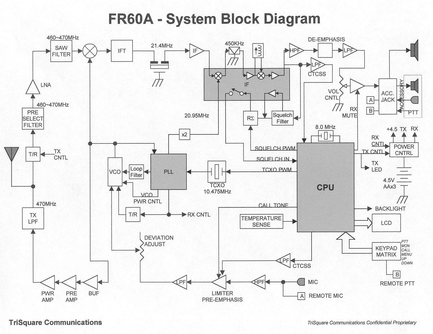
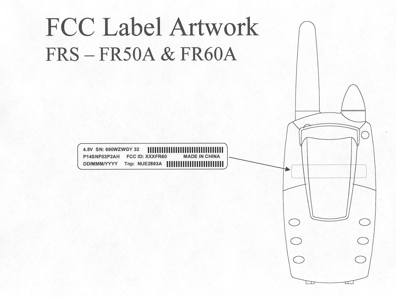
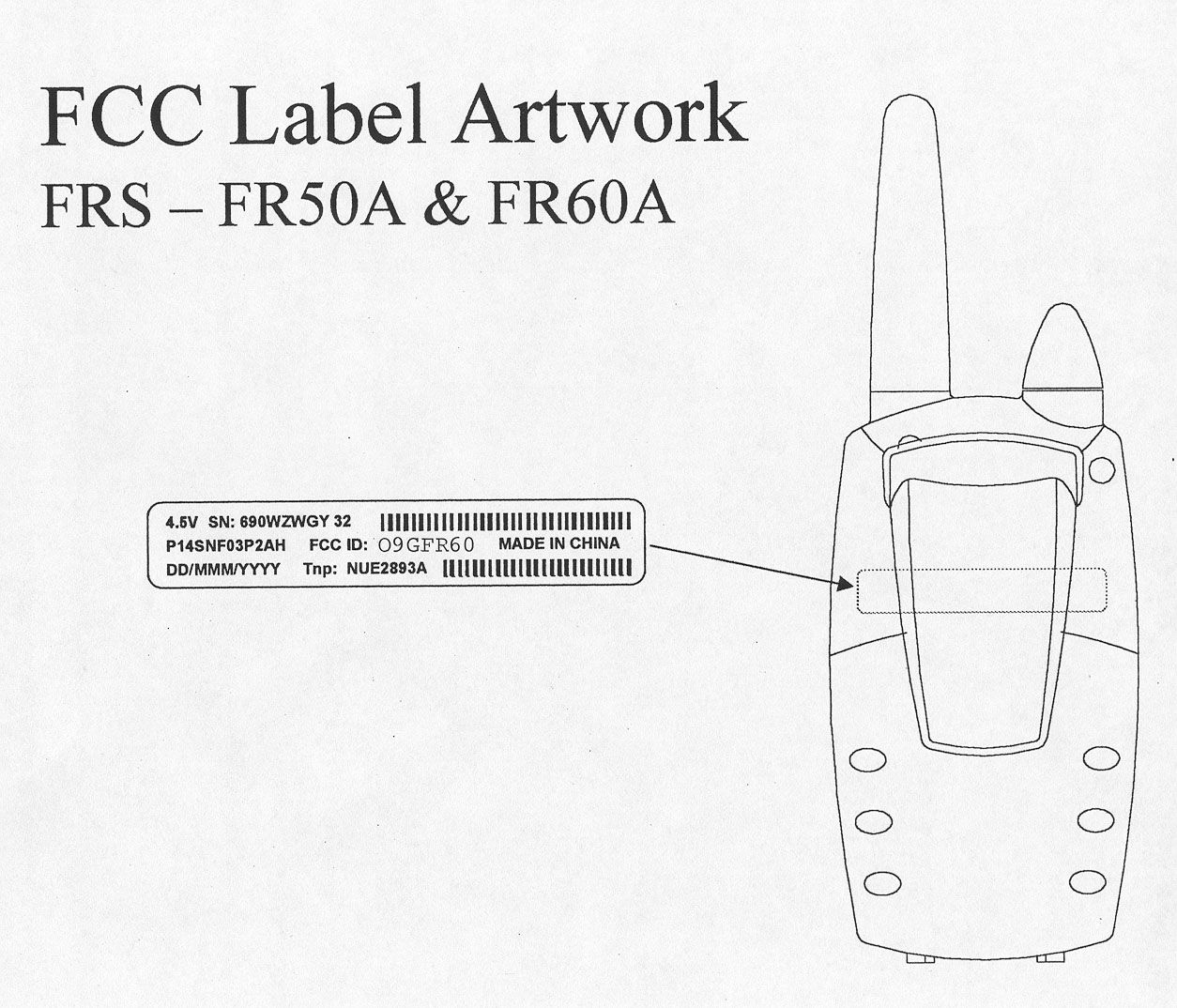
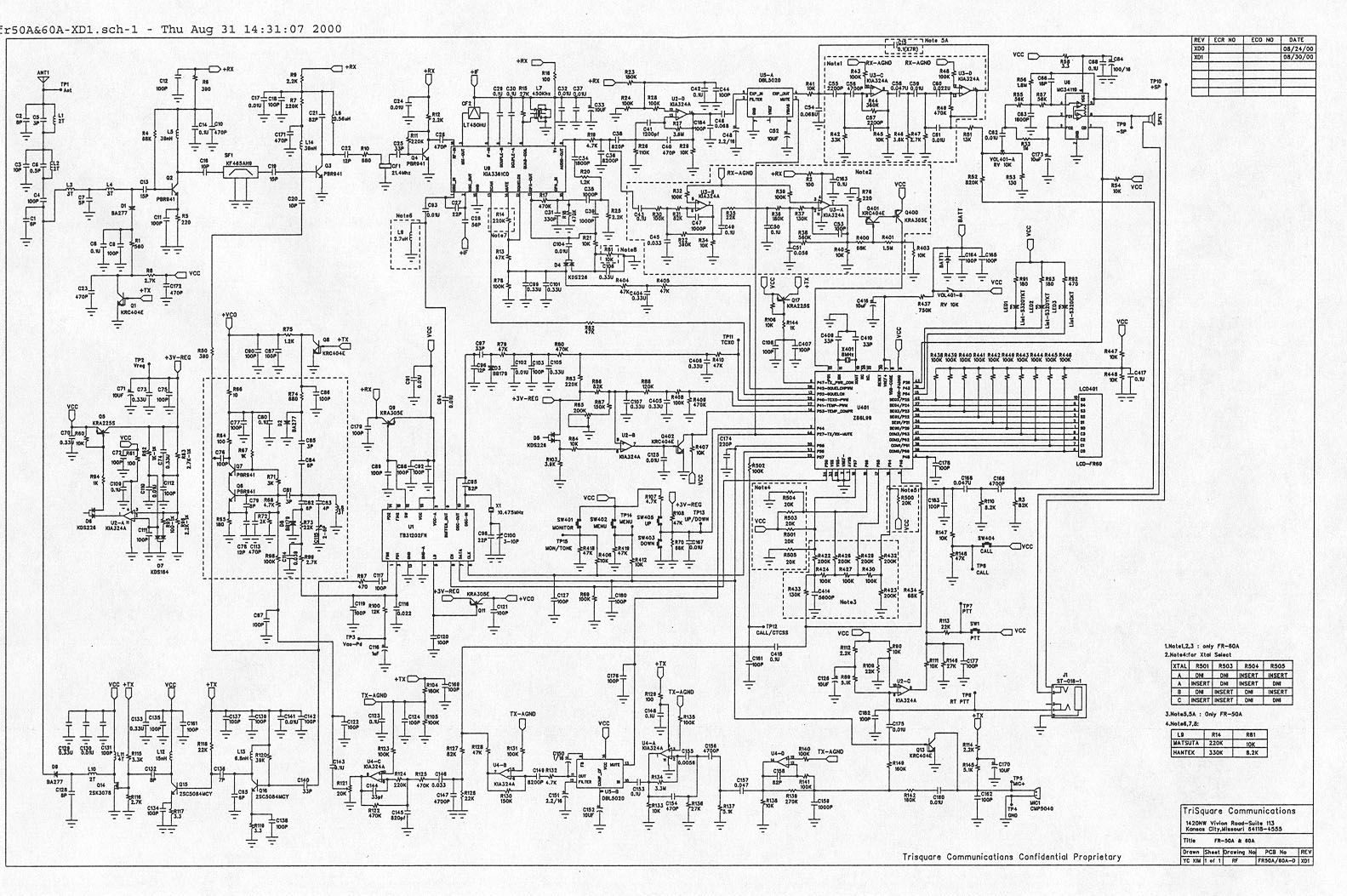
Document Text
Text extracted from the exhibit documents filed with the FCC. Open a document above to read the original.
External Photos
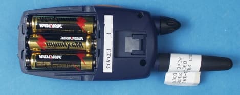
Front View Back View Right Side View Left Side View Batter y Co mpartme nt
Internal Photos
Circuit Board – Track Side Circuit Board – Component Side Batter y Co mpartme nt
Operational Description
TRANSMITTER TUNE-UP AND ALIGNMENT FRS – FR50A and FR60A 1. Frequency Setting A. Connect a frequency counter or communications service monitor capable of at least one watt RF. B. Press the PTT switch. C. Adjust C100 trimmer capacitor such that the output frequency is equal to the channel frequency with a maximum error of +/- 300 Hz. C100 is located below the VCO shield can to the right of the crystal unit. 2. Deviation Adjustment A. Connect an audio generator to the microphone test terminals. The audio frequency should be set at 1KHz with a level of 8mv. B. Connect an FM deviation meter or communications service monitor to the antenna connector. Set the monitor to read peak deviation. C. Press the PTT switch. D. Adjust R121 for +/- 1.5 KHz deviation. R121 is located to the right of the VCO shield can.
RF Exposure Info
CELLTECH RESEARCH INC. Test Report S/N: 100400-27O9G 1955 Moss Court, Kelowna, Date(s) of Tests: October 10, 2000 B.C. CANADA V1Y 9L3 _________________________________________________________________________________________________________ © 2000 Celltech Research Inc. CERTIFICATE OF COMPLIANCE SAR EVALUATION This wireless mobile and/or portable device has been shown to be compliant for localized specific absorption rate (SAR) for uncontrolled environment/general exposure limits specified in ANSI/IEEE Std. C95.1-1992 and had been tested in accordance with the measurement procedures specified in ANSI/IEEE Std. C95.3-1999. (See test report). I attest to the accuracy of data. All measurements were performed by me or were made under my supervision and are correct to the best of my knowledge and belief. I assume full responsibility for the completeness of these measurements and vouch for the qualifications of all persons taking them. Celltech Research Inc. certifies that no party to this application has been denied FCC benefits pursuant to Section 5301 of the Anti-Drug Abuse Act of 1988, 21 U.S.C. 853(a). Shawn McMillen General Manager Celltech Research Inc. Test Lab: CELLTECH RESEARCH INC. Testing and Engineering Lab 1955 Moss Court Kelowna, B.C. Canada V1Y 9L3 Phone: 250 - 860-3130 Fax: 250 - 860-3110 Toll Free: 1-877-545-6287 e-mail: [email protected] web site: www.globuswireless.com Applicant Information: TRISQUARE COMMUNICATIONS INC. 1420 Vivion Road Kansas City, MO 64118-4555 Attn: Barry Vonada FCC ID: O9GFR60 Model(s): Motorola FR60A EUT Type: Portable Handheld FRS Radio Transceiver Modulation: FM (UHF Band) Tx Frequency Range: 462.5625 – 467.7125 MHz Max. RF Output Power: 0.5 Watts No. of Channels: 14 FCC Rule Part(s): 2.1093, ET Docket 96-326 CELLTECH RESEARCH INC. Test Report S/N: 100400-27O9G 1955 Moss Court, Kelowna, Date(s) of Tests: October 10, 2000 B.C. CANADA V1Y 9L3 _________________________________________________________________________________________________________ © 2000 Celltech Research Inc. TABLE OF CONTENTS 1.0 INTRODUCTION.................................................................. 1 2.0 DESCRIPTION OF EUT.......................................................... 1 3.0 SAR MEASUREMENT SYSTEM ............................................. 2 4.0 MEASUREMENT SUMMARY.................................................. 3 5.0 SAR LIMITS........................................................................ 3 6.0 DETAILS OF SAR EVALUATION............................................ 4 7.0 EVALUATION PROCEDURES................................................. 5 8.0 SYSTEM VALIDATION.......................................................... 5 9.0 SIMULATED EQUIVALENT TISSUES...................................... 6 10.0 TISSUE PARAMETERS......................................................... 6 11.0 SYSTEM SPECIFICATIONS.................................................... 7 12.0 TEST EQUIPMENT LIST........................................................ 8 13.0 MEASUREMENT UNCERTAINTIES........................................ 9 14.0 REFERENCES...................................................................... 10 APPENDIX A - SAR MEASUREMENT DATA........................................ 11 APPENDIX B - DIPOLE VALIDATION................................................ 12 APPENDIX C - PROBE CALIBRATION............................................... 13 APPENDIX D - TEST SETUP PHOTOGRAPHS..................................... 14 CELLTECH RESEARCH INC. Test Report S/N: 100400-27O9G 1955 Moss Court, Kelowna, Date(s) of Tests: October 10, 2000 B.C. CANADA V1Y 9L3 _________________________________________________________________________________________________________ © 2000 Celltech Research Inc. TRISQUARE COMMUNICATIONS FCC ID: O9GFR60 1 Motorola FR60A Portable Handheld FRS Radio Transceiver 1.0 INTRODUCTION This measurement report shows compliance of the TRISQUARE COMMUNICATIONS INC. Model: Motorola FR60A Portable Handheld FRS Radio Transceiver FCC ID: O9GFR60 with the regulations and procedures specified in FCC Part 2.1093, ET Docket 96-326 Rules for mobile and portable devices. The test procedures, as described in American National Standards Institute C95.1-1992 (1), FCC OET Bulletin 65–1997 were employed. A description of the product and operating configuration, detailed summary of the test results, methodology and procedures used in the evaluation, equipment used, and the various provisions of the rules are included within this test report. 2.0 DESCRIPTION of Equipment Under Test (EUT) Front of EUT Left Side of EUT Right Side of EUT Rear of EUT EUT with headset Modulation FM (UHF Band) Rule Part(s) FCC 2.1093; ET Docket 96.326 No. of Channels 14 EUT Type Portable Handheld FRS Radio Transceiver Tx Frequency Range (MHz) 462.5625 - 467.7125 FCC ID O9GFR60 Max. RF Output Power 0.5 Watts Model No.(s) Motorola FR60A Antenna Type Fixed Serial No. Pre-production Power Supply 1.5V AA Alkaline Battery (x3) CELLTECH RESEARCH INC. Test Report S/N: 100400-27O9G 1955 Moss Court, Kelowna, Date(s) of Tests: October 10, 2000 B.C. CANADA V1Y 9L3 _________________________________________________________________________________________________________ © 2000 Celltech Research Inc. TRISQUARE COMMUNICATIONS FCC ID: O9GFR60 2 Motorola FR60A Portable Handheld FRS Radio Transceiver 3.0 SAR MEASUREMENT SYSTEM Celltech Research SAR measurement facility utilizes the Dosimetric Assessment System (DASY™) manufactured by Schmid & Partner Engineering AG (SPEAG™) of Zurich, Switzerland. The DASY system is comprised of the robot controller, computer, near-field probe, probe alignment sensor, and the generic twin phantom containing brain or muscle equivalent material (see Figure 6). The robot is a six-axis industrial robot performing precise movements to position the probe to the location (points) of maximum electromagnetic field (EMF). A cell controller system contains the power supply, robot con…
Text truncated - open the document above for the full version.
RF Exposure Info
The information provided in this document supersedes the general safety information contained in user guides published prior to October 2000. For infor-mation regarding radio use in a hazardous atmosphere please refer to the Factory Mutual (FM) Approval Manual Supplement or Instruction Card, which is included with radio models that offer this capability. RF OPERATIONAL CHARACTERISTICS Your radio contains a transmitter and a receiver. When it is ON, it receives and transmits radio frequency (RF) energy. EXPOSURE TO RADIO FREQUENCY ENERGY Your Motorola radio is designed to comply with the following national and interna-tional standards and guidelines regarding exposure of human beings to radio frequency electromagnetic energy (EME): • United States Federal Communications Commission, Code of Federal Regulations; 47 CFR part 2 sub-part J • American National Standards Institute (ANSI) / Institute of Electrical and Electronic Engineers (IEEE) C95. 1-1992 • Institute of Electrical and Electronic Engineers (IEEE) C95.1-1999 Edition • National Council on Radiation Protection and Measurements (NCRP) of the United States, Report 86, 1986 • International Commission on Non-Ioniz- ing Radiation Protection (ICNIRP) 1998 • National Radiological Protection Board of the United Kingdom 1995 • Ministry of Health (Canada) Safety Code 6. Limits of Human Exposure to Radiofre-quency Electromagnetic Fields in the Fre-quency Range from 3 kHz to 300 GHz, 1999 • Australian Communications Authority Radiocommunications (Electromagnetic Radiation - Human Exposure) Standard 1999 (applicable to wireless phones only) PORTABLE RADIO OPERATION AND EME EXPOSURE To assure optimal radio performance and make sure human exposure to radio frequency electromagnetic energy (EME) is within the guidelines set forth in the above standards, always adhere to the following procedures: Antenna Care Use only the supplied or an approved replacement antenna. Unauthorized antennas, modifications, or attachments could damage the radio and may violate FCC regulations. DO NOT hold the antenna when the radio is “IN USE.” Holding the antenna affects call quality and may cause the radio to operate at a higher power level than needed. Two-way Radio Operation When using your radio as a traditional two-way radio, hold the radio in a vertical posi-tion with the microphone 1 to 2 inches (2.5 to 5.0 cm) away from your lips. Body-worn Operation To maintain compliance with FCC RF exposure guidelines, if you wear a radio on your body when transmitting, always place the radio in a Motorola supplied or approved clip, holder, holster, case, or body harness. Use of non-Motorola-approved accessories may exceed FCC RF exposure guidelines. I f you do not use a body-worn accessory, ensure the antenna is at least 1 inch (2.5 cm) from your body when transmitting . Data Operation When using any data feature of the radio, with or without an accessory cable, position the antenna of the radio at least 1 inch (2.5 cm) from the body . Approved Accessories For a list of approved Motorola accessories look in the appendix or accessory section of your radio’s User Guide. ELECTROMAGNETIC INTERFERENCE/COMPATIBILITY NOTE: Nearly every electronic device is susceptible to electromagnetic interference (EMI) if inadequately shielded, designed or otherwise configured for electromagnetic compatibility. Facilities To avoid electromagnetic interference and/or compatibility conflicts, turn off your radio in any facility where posted notices instruct you to do so. Hospitals or health care facilities may be using equipment that is sensitive to external RF energy. Aircraft When instructed to do so, turn off your radio when on board an aircraft. Any use of a radio must be in accordance with applicable regulations per airline crew instructions. Medical Devices • Pacemakers The Health Industry Manufacturers Asso-ciation recommends that a minimum sep-aration of 6 inches (15 cm) be maintained between a handheld wireless radio and a pacemaker. These recommendations are consistent with the independent research by, and recommendations of, Wireless Technology Research.Persons with pacemakers should: • ALWAYS keep the radio more than 6 inches (15 cm) from their pacemaker when the radio is turned ON. • not carry the radio in the breast pocket. • use the ear opposite the pacemaker to minimize the potential for interference. • turn the radio OFF immediately if you have any reason to suspect that interference is taking place. • Hearing Aids Some digital wireless radios may interfere with some hearing aids. In the event of such interference, you may want to consult your hearing aid manufacturer to discuss alternatives. • Other Medical Devices If you use any other personal medical device, consult the manufacturer of your device to determine if it is adequately shielded from RF energy. Your physician may be able to assist you in obtaining this information. SAFETY AND GENERAL Use While Driving Check the laws and regulations on the use of radios in the area where you drive. Always obey them.When using your radio while driving, please: • Give full attention to driving and to the road. • Use hands-free operation, if available. • Pull off the road and park before making or answering a call if driving conditions so require. FOR VEHICLES WITH AN AIR BAG Do not place a portable radio in the area over an air bag or in the air bag deployment area. Air bags inflate with great force. If a portable radio is placed in the air bag deployment area and the air bag inflates, the radio may be propelled with great force and cause serious injury to occupants of the vehicle. POTENTIALLY EXPLOSIVEATMOSPHERES Turn off your radio prior to entering any area with a potentially explosive atmosphere, unless it is a radio type especially qualified for use in such areas as “Intrinsically Safe” (for example, Factory Mutual, CSA, or UL Approved). Do not remove, install, or charge batteries in such areas. Sparks in a potentially explosive a…
Text truncated - open the document above for the full version.
Test Report
ENGINEERING STATEMENT For Type Certification of TriSquare Communications Model No: FR60A FCC ID: XXXFR60 I am an Electronics Engineer, a principal in the firm of Hyak Laboratories, Inc., Springfield, Virginia. My education and experience are a matter of record with the Federal Communications Commission. Hyak Laboratories, Inc. has been authorized by TriSquare Communications, to make type certification measurements on the FR60 transceiver. These tests made by me or under my supervision in our Springfield laboratory. Test data and documentation required by the FCC for Type Certification are included in this report. The data verifies that the above mentioned transceiver meets FCC requirements and Type Certification is requested. ______________________________ Rowland S. Johnson Dated: September 7, 2000 A. INTRODUCTION The following data are submitted in connection with this request for type certification of the FR60 transceiver in accordance with Part 2, Subpart J of the FCC Rules. The FR60 is a portable, battery operated, UHF, frequency modulated transceiver intended for 12.5 kHz channel family radio service applications in the 462.5625-467.7125 MHz band. It operates from a nominal 4.5 Vdc battery supply. MFR rated output power is 0.5 watts ERP. B. GENERAL INFORMATION REQUIRED FOR TYPE CERTIFICATION (Paragraph 2.983 of the Rules) 1. Name of applicant: TriSquare Communications 2. Identification of equipment: FCC ID: XXXFR60 a. The equipment identification label is submitted as a separate exhibit. b. Photographs of the equipment are submitted as a separate exhibit. 3. Quantity production is planned. 4. Technical description: a. 11k0F3E emission b. Frequency range: 462.5625 - 467.7125 MHz. c. Operating power of transmitter is fixed at the factory at less than 0.5 W ERP. d. Maximum power permitted is 0.5 watts, and the FR60 fully complied with that power limitation. e. The dc voltage and dc currents at final amplifier: Collector voltage: 4.4 Vdc Collector current: 0.40 A f. Function of each active semiconductor device: See Appendix 1. g. Complete schematic diagram is submitted as a separate exhibit. h. A draft instruction manual is submitted as a separate exhibit. i. The transmitter tune-up procedure is submitted as a separate exhibit. 2 B. GENERAL INFORMATION (continued) j. A description of circuits for stabilizing frequency is included in Appendix 2. k. A description of circuits and devices employed for suppression of spurious radiation and for limiting modulation is included in Appendix 3. l. Not applicable. 5. Data for 2.985 through 2.997 follow this section. C. RF Power Output (Paragraph 2.985(a) of the Rules) The FR60 has a permanently attached built-in antenna without provisions for a coaxial connector. Therefore RF power output was calculated, see Table 1. The transmitter was tuned by the factory. TABLE 1 Operating Freq., MHz Power watts into a dipole antenna 462.5625 0.48 D. MODULATION CHARACTERISTICS 1. A curve showing frequency response of the transmitter is shown in Figure 1. Reference level was audio signal output from a Boonton 8220 modulation meter with one kHz deviation. Audio output was measured with an Audio Precision System One integrated test system. 2. Modulation limiting curves are shown in Figure 2, using a Boonton 8220 modulation meter. Signal level was established with a Audio Precision System One integrated test system. The curves show compliance with paragraphs 2.987(b). 3. Figure 3 is a graph of the post-limiter low pass filter which provides a roll-off of 60Logf/3 dB where f is audio frequency in kHz. Measurements were made following EIA RS-152B with an Audio Precision System One integrated test system on the Boonton 8220 modulation meter audio output. 3 4. Occupied Bandwidth (Paragraphs 2.989(c) of the Rules) Figure 4 is a plot of the sideband envelope of the transmitter output taken with a Tektronix 494P spectrum analyzer. Modulation corresponded to conditions of 2.989(c)(1) and consisted of 2500 Hz tone at an input level 16 dB greater than that necessary to produce 50% modulation at 2690 Hz, the frequency of maximum response. Measured modulation under these conditions was 2.4 kHz. Emission designator: (2M + 2D) (2 x 3 kHz) + (2 x 2.5 kHz)* = 11k0F3E *Deviation @ 1500 Hz was 2.5 kHz. 4 FIGURE 1 MODULATION FREQUENCY RESPONSE MODULATION FREQUENCY RESPONSE FCC ID: XXXFR60 FIGURE 1 5 FIGURE 2 AUDIO LIMITER CHARACTERISTICS AUDIO LIMITER CHARACTERISTICS FCC ID: XXXFR60 FIGURE 2 6 FIGURE 3 AUDIO LOW PASS FILTER RESPONSE AUDIO LOW PASS FILTER RESPONSE FCC ID: XXXFR60 FIGURE 3 7 FIGURE 4 OCCUPIED BANDWIDTH ATTENUATION IN dB BELOW MEAN OUTPUT POWER Required On any frequency more than 50% up to and including 100% of the 25 authorized bandwidth, 12.5 kHz (6.25-12.5 kHz) On any frequency more than 100%, up to and including 250% of the 35 authorized bandwidth (12.5-31.25 kHz) On any frequency removed from the assigned frequency by more 43+10LogP = 40 than 250% of the authorized (P = 0.48) bandwidth (over 31.25 kHz) OCCUPIED BANDWIDTH FCC ID: XXXFR60 FIGURE 4 8 D. MODULATION CHARACTERISTICS (Continued) The plots are within FCC limits. The horizontal scale frequency) is 10 kHz per division and the vertical scale amplitude) is a logarithmic presentation equal to 10 dB per division. E. SPURIOUS EMISSIONS AT THE ANTENNA TERMINALS (Paragraph 2.991 of the Rules) The FR60 has a permanently attached antenna. There is no connector for an external antenna. Therefore, no antenna terminal conducted measurements were made. F. DESCRIPTION OF RADIATED SPURIOUS MEASUREMENT FACILITIES A description of the Hyak Laboratories’ radiation test facility is a matter of record with the FCC. The facility was accepted for radiation measurements from 25 to 1000 MHz on October 1, 1976 and is currently listed as an accepted site. G. FIELD STRENGTH MEASUREMENTS OF SPURIOUS RADIATION Field intensity measurements of radiated spurious emissions from the FR60 were made with a Tektronix 494P spectrum analyzer usi…
Text truncated - open the document above for the full version.
Contact Information
Applicant
Philip Staley(Product Development Manager)
Technical Contact
Hyak Laboratories, Inc.Rowland S Johnson
[email protected](703) 451-1188
7011 Calamo St., Suite 107 · Springfield, Virginia · United States
Non-Technical Contact
Hyak Laboratories, Inc.Georgia Hall
[email protected](703) 451-1188
Test Firm
Hyak Laboratories, Inc.Rowland Johnson
703-451-1188
Technical Specifications
| # | Rule Parts | Frequency Range | Power Output | Emission | Tolerance |
|---|---|---|---|---|---|
| 1 | 95B | 462.5625 MHz - 467.7125 MHz | 480.00 mW | 11k0F3E | 0.0002500000 % |
Other Applications from Trisquare Communications Inc.
O9GWBASE
Oct 28, 2007WIRELESS MICROPHONE SYSTEM-BASE
Equipment Class
DXX - Part 15 Low Power Communication Device Transmitter
O9GWMIC
Oct 28, 2007MIC TRANSCEIVER
Equipment Class
DXX - Part 15 Low Power Communication Device Transmitter
O9GDVMICT
Feb 05, 2006LOW POWER CAR TRANSCEIVER
Equipment Class
DXX - Part 15 Low Power Communication Device Transmitter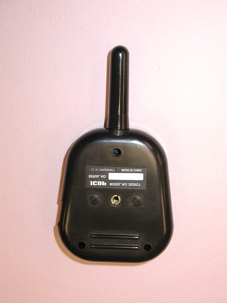
O9G2020ICT
May 02, 2005In Car Transceiver
Equipment Class
DXX - Part 15 Low Power Communication Device Transmitter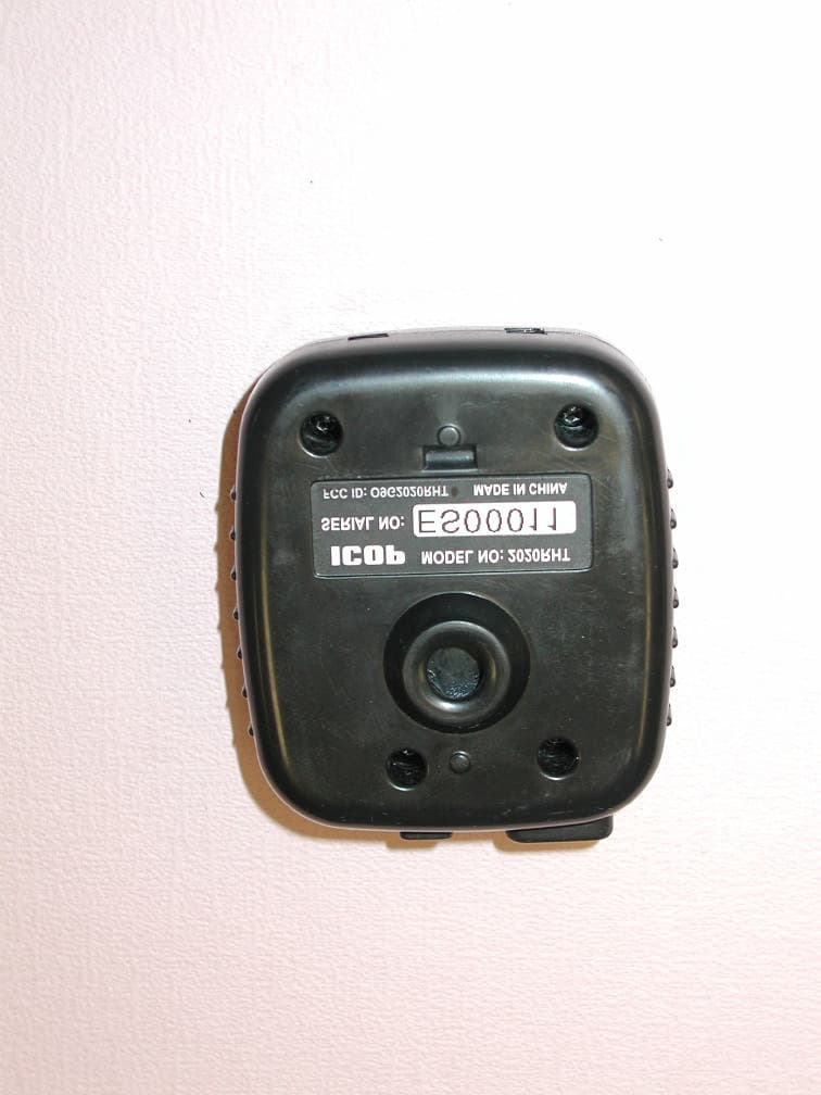
O9G2020RHT
May 01, 2005Remote Transceiver
Equipment Class
DXX - Part 15 Low Power Communication Device Transmitter