O9GFRS440FRS Transceiver
Trisquare Communications Inc.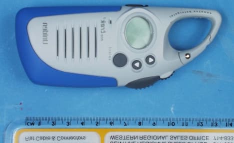
Click to zoom
Application Details
- Equipment Class
- FRF - Part 95 Family Radio Face Held Transmitter
- Date of Grant
- Apr 24, 2001
- Application Purpose
- Original Equipment
- Date of Application
- Mar 05, 2001
- Equipment Note
- FRS Transceiver
- Frequency Range
- 462.56250000 - 467.71250000
- Country
- United States
Documents & Files
Document Text
Text extracted from the exhibit documents filed with the FCC. Open a document above to read the original.
Users Manual
FRS420 – User Instruction Guide – Content Draft TriSquare Communications Draft for content only – customer to define layout and additional graphics Page 1 Controls1) On/Off/Volume control 2) PTT button 3) Call/Menu b utto n 4) Up button 5) Down b utto n 6) Accessory jack LCD Dis play1) Channel Number – displays the FRS channel (1-14). 2) CTCSS Code Number – indicates the current sub-audible code selected (0-38) 3) SCAN – displays when the scan feature is active. 4) Vibrate Icon – displays when the vibrate feature is selected. FCC Information• This device complies with Part 15 of theFCC Rules. Operation is subject to thefollowing two conditions: (1) This devicema y no t ca use har mful interference, a nd (2)this device must accept any interferencereceived, including interference that maycause undesired operation. • Important: Changes or modifications to thisunit not expressly approved by Uniden couldvoid your authority to operate this unit.Your radio is set up to trans mi t a regulatedsignal o n a n assigned freq ue ncy. It isagainst the law to alter the settings inside theradio to exceed those limitations. Anyadjustments to your radio must be made byqualified technicians. • To be safe and sure:o Never open your radio’s case o Never change or replace anything in yourradio except the batteries. • Your radio might cause TV or radiointerference even when it is operatingproperly. To determine whether your radiois causing the interference, turn it off. If theinterference goes away, your radio iscausing it. Try to eliminate the interferenceby moving your radio away from thereceiver. If you cannot eliminate theinterference, the FCC requires that you stopusing the radio. Safety Guidelines• Audio Accessories: Do not operate theradio with audio accessories at high volumelevels. Hearing experts advise againstcontinuous high volume operation. If youexperience a ringing in your ears, reduce thevolume level or discontinue use. Alwaysmake sure the radio is turned off beforeplugging audio accessories into theaccessory jack. • Hazardous Environments: Do not operatethe radio in hazardous environments.Explosion or fire may result. Do not operatethe radio near unshielded electrical blastingcaps. Under certain conditions, radios caninterfere with blasting operations and maycause an explosion. Turn your radio OFF toprevent accidental transmission w hen in ablasting area or in areas posted: “Turn offtwo-way radios.” Construction crews oftenuse remote control RF devices to set offexplosives. • Care and Safety: To clean the radio, use asoft cloth da mpe ned w ith w ater. Do not usecleaners or solvents because they can harmthe body of the unit and leak inside, causingpermanent damage. Use a dry, lint-freecloth to clean the battery contacts. Do notsubmerge the unit in water. If the unit getswet, turn it off and remove the batteriesimmediately. Dry the battery compartmentwith a soft cloth to mi ni mi ze pote ntial waterdamage. Leave the battery compartmentcover off overnight to ensure completedrying. Do not use the radio until the unit iscompletely dry. picture picture FRS420 – User Instruction Guide – Content Draft TriSquare Communications Draft for content only – customer to define layout and additional graphics Page 2 We lco meCongratulations on your purchase of theUniden FRS420 Family Radio. This product isa lightweight, palm-sized radio with a uniqueCarabiner design allow ing yo u to “clip” theradio to almost anything and carry it almostanywhere. Use it at shopping malls,amusement parks, or sporting events to stay incontact with family and friends, or in aneighborhood watch for vital communication.This compact, state-of-the-art device isequipped with the following features: o 14 Channels o 38 CTCSS Codes o Up to 2 mile range* o LCD Display o 5 Selectable Call Tone Alerts o Vibrate Alert for incoming calls o Channel Scan o Cha nnel Mo ni tor o Audible Low Battery Indicator o Supports Optional HeadsetAccessories o Supports Optional NiMH Battery Pack * Range may very depending on environmentaland/or topographical conditions.Optional AccessoriesYour package contains the FRS420 radio, thisreference guide, and a product registration card.You will need to purchase 3 AA Alkalinebatteries in order to operate the unit. Thefollowing optional accessories may be purchased from your Uniden dealer or [need toadd other means]. o Earset Mic w/ PTT – #EM2468 o Vox Headset Mic – #EMV2469 o NiMH Battery Pack – #TBD o AC Wall Charger – #TBD o Car Char ger – #TBD o Battery Covers – #TBD Battery InstallationYour FRS420 radio uses 3 AA Alkalinebatteries for power. To install the batteries:1) Make sure your radio is OFF. 2) Remove the battery compartment door bysliding it down from the unit. 3) Install 3 AA Alkaline batteries (notincluded) into the battery compartment.Be certain to follow the + and – symbols inthe compartment. Installing the batteriesincorrectly will prevent the unit fromoperating. 4) Optional: Your FRS420 radio can bepowered using an optional NiMH batterypack specifically designed for this model.Remove the alkaline batteries and installthe battery pack by inserting into thebatter y co mpartme nt. Follow theinstructions found with the NiMHaccessory. 5) Replace the battery compartment door bypushing it up until it is secure. Low Battery AlertWhen the batteries in the unit are low, the unitwill emit a “low battery” tone indication.Replace the batteries immediately to continueusing the radio.Using Your RadioIn order to get the most out of your new radio,read this reference guide completely beforeattempting to operate the unit.Turning the Radio On and Adjusting Volume1) Rotate the on/off/volume control clockwise to turn the unit ON and increasethe speaker volume 2) Rotate the on/off/volume control counterclockwise to decrease the speakervolume and turn the unit OFF. Adjusting the Sound (Key Beeps)Your radio emits a beep each time one of thebuttons is pressed. To turn this sound OFF,press PTT while turning on the radio. To …
Text truncated - open the document above for the full version.
Cover Letter(s)
TriSquare Communications 1420 NW Vivion Rd., Suite 113, Kansas City, Missouri 64118 February 6, 2001 Federal Communications Commission Authorization & Evaluation Division 7435 Oakland Mills Road Columbia, MD 21046 Ref: Confidentiality Request; FCC ID: O9GFRS440 In connection with our submission of the above referenced product for FCC approval, TriSquare Communications is requesting confidentiality of certain sections of the accompanying application. The sections for which confidentiality is requested are: • System Block Diagram • Schematic Diagrams • List of Semiconductors • Technical Descriptions This request is made under the provisions of Section 0.457(d) of the Commission’s Rules, and Section 552(b)(4) of the Freedom of Information Act. The material for which confidentiality is requested falls within the scope of Section 552(b)(4) as trade secrets and includes material covered by Section 0.459 of the Commission’s Rules. Regards, Barry Vonada Director of Operations TriSquare Communications Phone: 816-505-3575 Fax:816-505-3579
External Photos
Front View Back View Side View PTT Side View
ID Label/Location Info
FCC ID: O9GFRS440
Internal Photos
Batter y Co mpartme nt PCB Component Side PCB Track Side
Parts List/Tune Up Info
TRANSMITTER TUNE-UP AND ALIGNMENT FRS400/420/440 Series FCC ID: O9GFRS440 1. Frequency Setting A. Connect a frequency counter or communications service monitor capable of at least one watt RF. B. Press the PTT switch. C. Adjust CT300 trimmer capacitor such that the output frequency is equal to the channel frequency with a maximum error of +/- 300 Hz. CT300 is located below the VCO shield can to the left of the crystal unit. 2. Deviation Adjustment A. Connect an audio generator to the microphone test terminals. The audio frequency should be set at 1KHz with a level of 8mv. B. Connect an FM deviation meter or communications service monitor to the antenna connector. Set the monitor to read peak deviation. C. Press the PTT switch. D. Adjust RV230 for +/- 1.5 KHz deviation. RV230 is located to the lower right of the VCO shield can.
RF Exposure Info
CELLTECH RESEARCH INC. Test Report S/N: 030801-70O9G 1955 Moss Court, Kelowna, Date(s) of Tests: March 12, 2001 B.C. CANADA V1Y 9L3 _________________________________________________________________________________________________________ © 2001 Celltech Research Inc. CERTIFICATE OF COMPLIANCE IC RSS-102 SAR EVALUATION This wireless mobile and/or portable device has been shown to be compliant for localized Specific Absorption Rate (SAR) for uncontrolled environment / general exposure limits specified in ANSI/IEEE Std. C95.1-1992 and had been tested in accordance with the measurement procedures specified in ANSI/IEEE Std. C95.3-1999. I attest to the accuracy of data. All measurements were performed by me or were made under my supervision and are correct to the best of my knowledge and belief. I assume full responsibility for the completeness of these measurements and vouch for the qualifications of all persons taking them. Celltech Research Inc. certifies that no party to this application has been denied FCC benefits pursuant to Section 5301 of the Anti-Drug Abuse Act of 1988, 21 U.S.C. 853(a). Shawn McMillen General Manager Celltech Research Inc. Test Lab: CELLTECH RESEARCH INC. Testing and Engineering Lab 1955 Moss Court Kelowna, B.C. Canada V1Y 9L3 Phone: 250 - 860-3130 Fax: 250 - 860-3110 Toll Free: 1-877-545-6287 e-mail: [email protected] web site: www.globuswireless.com Applicant Information: TRISQUARE COMMUNICATIONS INC. 1420 NW Vivion Rd., Suite 113 Kansas City, MO 64118 Attn: Mr. Barry Vonada Tel: (816) 505-3575 Fax: (816) 505-3579 FCC ID: O9GFRS440 Model(s): FRS 400 / FRS 420 EUT Type: Portable FRS PTT Radio Transceiver Modulation: FM Tx Frequency Range: 462.5625 - 467.7125 MHz Max. RF Output Power: 0.49 Watts No. of Channels: 14 IC Rule Part(s): RSS-102 CELLTECH RESEARCH INC. Test Report S/N: 030801-70O9G 1955 Moss Court, Kelowna, Date(s) of Tests: March 12, 2001 B.C. CANADA V1Y 9L3 _________________________________________________________________________________________________________ © 2001 Celltech Research Inc. TABLE OF CONTENTS 1.0 INTRODUCTION.................................................................. 1 2.0 DESCRIPTION OF EUT.......................................................... 1 3.0 SAR MEASUREMENT SYSTEM ............................................. 2 4.0 MEASUREMENT SUMMARY.................................................. 3-4 5.0 SAR LIMITS........................................................................ 5 6.0 DETAILS OF SAR EVALUATION............................................ 5 7.0 EVALUATION PROCEDURES................................................. 6 8.0 SYSTEM VALIDATION.......................................................... 6 9.0 SIMULATED EQUIVALENT TISSUES...................................... 7 10.0 TISSUE PARAMETERS......................................................... 7 11.0 SYSTEM SPECIFICATIONS.................................................... 8 12.0 TEST EQUIPMENT LIST........................................................ 9 13.0 MEASUREMENT UNCERTAINTIES........................................ 10 14.0 REFERENCES...................................................................... 11 APPENDIX A - SAR MEASUREMENT DATA........................................ 12 APPENDIX B - DIPOLE VALIDATION................................................ 13 APPENDIX C - PROBE CALIBRATION............................................... 14 APPENDIX D - TEST SETUP PHOTOGRAPHS..................................... 15 CELLTECH RESEARCH INC. Test Report S/N: 030801-70O9G 1955 Moss Court, Kelowna, Date(s) of Tests: March 12, 2001 B.C. CANADA V1Y 9L3 _________________________________________________________________________________________________________ © 2001 Celltech Research Inc. TRISQUARE COMM. Model: UNIDEN FRS 400 / FRS 420 1 Portable FRS Radio Transceiver (462.5625 - 467.7125 MHz) 1.0 INTRODUCTION This measurement report shows compliance of the TRISQUARE COMMUNICATIONS INC. Model: Uniden FRS 400 / FRS 420 Portable FRS Radio Transceiver FCC ID: O9GFRS440 with the regulations and procedures specified in RSS-102 of Industry Canada for mobile and portable devices. The test procedures, as described in American National Standards Institute C95.1-1992 (1), FCC OET Bulletin 65–1997 were employed. A description of the product and operating configuration, detailed summary of the test results, methodology and procedures used in the evaluation, equipment used, and the various provisions of the rules are included within this test report. 2.0 DESCRIPTION of Equipment Under Test (EUT) Front of EUT Left Side of EUT Right Side of EUT R ear of EUT Modulation FM Rule Part(s) IC RSS-102 No. of Channels 14 EUT Type Portable FRS Radio Transceiver Tx Frequency Range (MHz) 462.5625 - 467.7125 FCC ID O9GFRS440 Max. RF Output Power 0.49 Watts Model No.(s) Uniden FRS 400/FRS 420 Antenna Type Integral Serial No. Pre-production Power Supply 1.5V AA Alkaline Battery (x3) CELLTECH RESEARCH INC. Test Report S/N: 030801-70O9G 1955 Moss Court, Kelowna, Date(s) of Tests: March 12, 2001 B.C. CANADA V1Y 9L3 _________________________________________________________________________________________________________ © 2001 Celltech Research Inc. TRISQUARE COMM. Model: UNIDEN FRS 400 / FRS 420 2 Portable FRS Radio Transceiver (462.5625 - 467.7125 MHz) 3.0 SAR MEASUREMENT SYSTEM Celltech Research SAR measurement facility utilizes the Dosimetric Assessment System (DASY™) manufactured by Schmid & Partner Engineering AG (SPEAG™) of Zurich, Switzerland. The DASY system is comprised of the robot controller, computer, near-field probe, probe alignment sensor, and the generic twin phantom containing brain or muscle equivalent material. The robot is a six-axis industrial robot performing precise movements to position the probe to the location (points) of maximum electromagnetic field (EMF). A cell controller system contains the power supply, robot controller, teach pendant (Joystick),…
Text truncated - open the document above for the full version.
Test Report
ENGINEERING STATEMENT For Type Certification of Trisquare Communications Model No: FRS420 FCC ID: O9GFRS440 I am an Electronics Engineer, a principal in the firm of Hyak Laboratories, Inc., Springfield, Virginia. My education and experience are a matter of record with the Federal Communications Commission. Hyak Laboratories, Inc. has been authorized by Trisquare Communications to make type certification measurements on the model FRS420 transceiver. These tests made by me or under my supervision in our Springfield laboratory. Test data and documentation required by the FCC for Type Certification are included in this report. The data verifies that the above mentioned transceiver meets FCC requirements and Type Certification is requested. ______________________________ Rowland S. Johnson Dated: March 2, 2001 A. INTRODUCTION The following data are submitted in connection with this request for type certification of the model FRS420 transceiver in accordance with Part 2, Subpart J of the FCC Rules. The model FRS420 is a portable, battery operated, UHF, frequency modulated transceiver intended for 12.5 kHz channel family radio service applications in the 462.5625-467.7125 MHz band. It operates from a nominal 4.8 Vdc battery supply. MFR rated output power is 0.5 watts ERP(d) B. GENERAL INFORMATION REQUIRED FOR TYPE CERTIFICATION (Paragraph 2.983 of the Rules) 1. Name of applicant: Trisquare Communications 2. Identification of equipment: FCC ID: O9GFRS440 a. The equipment identification label is submitted as a separate exhibit. b. Photographs of the equipment are submitted as a separate exhibit. 3. Quantity production is planned. 4. Technical description: a. 11k0F3E emission b. Frequency range: 462.5625 - 467.7125 MHz. c. Operating power of transmitter is fixed at the factory at less than 0.5 W ERP(d) d. Maximum power permitted is 0.5 watts, and the model FRS420 fully complied with that power limitation. e. The dc voltage and dc currents at final amplifier: Collector voltage: 4.4 Vdc Collector current: 0.57 A f. Function of each active semiconductor device: See Semiconductors exhibit. g. Complete schematic diagram is submitted as a separate exhibit. h. A draft instruction manual is submitted as a separate exhibit. i. The transmitter tune-up procedure is submitted as a separate exhibit. 2 B. GENERAL INFORMATION (continued) j. A description of circuits for stabilizing frequency is included in Technical Description exhibit. k. A description of circuits and devices employed for suppression of spurious radiation and for limiting modulation is included in Technical Description exhibit. l. Not applicable. 5. Data for 2.985 through 2.997 follow this section. C. RF_Power_Output (Paragraph 2.985(a) of the Rules) The model FRS420 has a permanently attached built-in antenna without provisions for a coaxial connector. Therefore RF power was determined by substitution. TABLE 1 Operating Freq., MHz Power watts into a dipole antenna 462.5625 0.49 D. MODULATION CHARACTERISTICS 1. A curve showing frequency response of the transmitter is shown in Figure 1. Reference level was audio signal output from a Boonton 8220 modulation meter with one kHz deviation. Audio output was measured with an Audio Precision System One integrated test system. 2. Modulation limiting curves are shown in Figure 2, using a Boonton 8220 modulation meter. Signal level was established with a Audio Precision System One integrated test system. The curves show compliance with paragraphs 2.987(b). 3. Figure 3 is a graph of the post-limiter low pass filter which provides a roll-off of 60Logf/3 dB where f is audio frequency in kHz. Measurements were made following EIA RS-152B with an Audio Precision System One integrated test system on the Boonton 8220 modulation meter audio output. 3 4. Occupied_Bandwidth (Paragraphs 2.989(c) of the Rules) Figure 4 is a plot of the sideband envelope of the transmitter output taken with a Tektronix 494P spectrum analyzer. Modulation corresponded to conditions of 2.989(c)(1) and consisted of 2500 Hz tone at an input level 16 dB greater than that necessary to produce 50% modulation at 2469 Hz, the frequency of maximum response. Emission designator: (2M + 2D) (2 x 3 kHz) + (2 x 2.5 kHz) = 11k0F3E 4 FIGURE 1 MODULATION FREQUENCY RESPONSE MODULATION FREQUENCY RESPONSE FCC ID: O9GFRS440 FIGURE 1 5 FIGURE 2 AUDIO LIMITER CHARACTERISTICS AUDIO LIMITER CHARACTERISTICS FCC ID: O9GFRS440 FIGURE 2 6 FIGURE 3 AUDIO LOW PASS FILTER RESPONSE AUDIO LOW PASS FILTER RESPONSE FCC ID: O9GFRS440 FIGURE 3 7 FIGURE 4 OCCUPIED BANDWIDTH ATTENUATION IN dB BELOW MEAN OUTPUT POWER Required On any frequency more than 50% up to and including 100% of the 25 authorized bandwidth, 12.5 kHz (6.25-12.5 kHz) On any frequency more than 100%, up to and including 250% of the 35 authorized bandwidth (12.5-31.25 kHz) On any frequency removed from the assigned frequency by more 43+10LogP = 40 than 250% of the authorized (P = 0.49) bandwidth (over 31.25 kHz) OCCUPIED BANDWIDTH FCC ID: O9GFRS440 FIGURE 4 8 D. MODULATION CHARACTERISTICS (Continued) The plots are within FCC limits. The horizontal scale frequency) is 10 kHz per division and the vertical scale amplitude) is a logarithmic presentation equal to 10 dB per division. E. SPURIOUS EMISSIONS AT THE ANTENNA TERMINALS (Paragraph 2.991 of the Rules) The model FRS420 has a permanently attached antenna. There is no connector for an external antenna. Therefore, no antenna terminal conducted measurements were made. F. DESCRIPTION OF RADIATED SPURIOUS MEASUREMENT FACILITIES A description of the Hyak Laboratories’ radiation test facility is a matter of record with the FCC. The facility was accepted for radiation measurements from 25 to 1000 MHz on October 1, 1976 and is currently listed as an accepted site. G. MEASUREMENTS OF SPURIOUS RADIATION Spurious emissions from the model FRS420 were made by substitution with a Tektronix 494P spectrum analyzer using Singer DM-105 for the measurements to 1 GHz, and EMCO 31…
Text truncated - open the document above for the full version.
Contact Information
Applicant
Philip Staley(Product Development Manager)
Technical Contact
Hyak Laboratories, Inc.Rowland S Johnson
[email protected](703) 451-1188
7011 Calamo St., Suite 107 · Springfield, Virginia · United States
Non-Technical Contact
Hyak Laboratories, Inc.Georgia Hall
[email protected](703) 451-1188
Test Firm
Hyak Laboratories, Inc.Rowland Johnson
703-451-1188
Technical Specifications
| # | Rule Parts | Frequency Range | Power Output | Emission | Tolerance |
|---|---|---|---|---|---|
| 1 | 95 | 462.5625 MHz - 467.7125 MHz | 500.00 mW | 11K0F3E | 0.0002500000 % |
Other Applications from Trisquare Communications Inc.
O9GWBASE
Oct 28, 2007WIRELESS MICROPHONE SYSTEM-BASE
Equipment Class
DXX - Part 15 Low Power Communication Device Transmitter
O9GWMIC
Oct 28, 2007MIC TRANSCEIVER
Equipment Class
DXX - Part 15 Low Power Communication Device Transmitter
O9GDVMICT
Feb 05, 2006LOW POWER CAR TRANSCEIVER
Equipment Class
DXX - Part 15 Low Power Communication Device Transmitter
O9G2020ICT
May 02, 2005In Car Transceiver
Equipment Class
DXX - Part 15 Low Power Communication Device Transmitter
O9G2020RHT
May 01, 2005Remote Transceiver
Equipment Class
DXX - Part 15 Low Power Communication Device Transmitter