O9GT5210Face Held FRS Transceiver
Trisquare Communications Inc.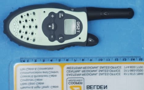
Click to zoom
Application Details
- Equipment Class
- FRF - Part 95 Family Radio Face Held Transmitter
- Date of Grant
- Jun 13, 2001
- Application Purpose
- Original Equipment
- Date of Application
- Apr 25, 2001
- Equipment Note
- Face Held FRS Transceiver
- Frequency Range
- 462.56250000 - 467.71250000
- Country
- United States
Documents & Files
Document Text
Text extracted from the exhibit documents filed with the FCC. Open a document above to read the original.
Users Manual
• No license fee or airtime charges! • Audible Call Tone Ringing option so your group can identify who’s calling • Keypad Lock Prevents your settings from being accidentally changed • Illuminated display Easy to read your settings in dark places • Batteries (not included) Requires 3 AA Alkaline batteries • Quick Release Swivel Belt Clip Included • Durable, fixed antenna Maximizes talk range • Up to 2 mile range Depending on terrain and conditions • “Roger” Beep Signals others you’re done talking • Scan (T5210 Only) Easily finds your group’s channel and code by searching all combinations • Talk Hands-Free (VOX) (T5220Only) “Voice activation” (VOX) Lets you talk hands-free when used with optional accessories • 1 Year Limited Warranty For warranty details call 1-800-353-2729 • Weather-resistant • 14 channels Privacy feature that helps minimize interference from other groups • Call Button Get others’ attention before you start talking • Low Battery Alert Audible tone and visual display tell you your battery is running down • User’s Guide included Accessories for T5000 series - Convenient headphones, mesh and waterproof carry cases available from your retailer or www .motorola.com WARNING CHOKING HAZARD - SMALL PARTS Not for children under 3 years. This product is not intended to be used as a toy or plaything. MOTOROLA, the stylized M Logo, TALKABOUT, and all other trademarks indicated as such herein are trademarks of Motorola, inc. ® Reg. U.S. pat. & Tm. Off. All other product or service names are the property of their respective owners. © 2001 Motorola, Inc. All rights reserved. Printed in China. Table of Contents Your New Radio Radio Diagram..........................................................2 Batteries To Install ..................................................................3 Radio Etiquette.........................................................3 Belt Clip To Attach...................................................................4 To Remove...............................................................4 Front Cover To Remove...............................................................4 To Attach...................................................................4 To Communicate Turn The Radio On....................................................5 Monitor Button...........................................................5 Channel Busy Indicator.............................................5 Adjust The Volume....................................................5 Time-out Timer..........................................................6 Menu/Lock Button......................................................6 Set The Channel........................................................6 Set The Code............................................................6 Call Tone......................................................................7 Set The Call Tone........................................................7 “Roger” Beep...............................................................7 Scan (T5210 Only).......................................................8 Hands-Free Use (VOX) (T5220 Only).........................9 Sending Messages......................................................9 Battery Meter.............................................................10 Low Battery Alert.......................................................10 Accessories To Use Audio Accessories.........................................10 Talk Range.................................................................11 Care Of Your Radio....................................................11 Safety and General Information Cautions and Warnings.........................................12-16 Troubleshooting Troubleshooting....................................................17-18 Warranty One Year Limited Warranty...................................19-22 Channel Frequency Chart..........................................23 Interference Eliminator Code Chart...........................24 Specifications.............................................................25 1 Your New Radio Motorola Talkabout T5210 and T5220 radios operate on Family Radio Service (FRS) designated frequencies.This license-free, short range, two-way radio service was established specifically for family and group recreational use. Use of this radio outside the country where it was intended to be distributed is subject to government regulations and may be prohibited. Push-To-Talk Button (PTT) Power/Volume Knob Accessory Jack Scroll Buttons Interference Eliminator Code Microphone Menu/Lock Button LED Indicator Light Monitor (mon) Battery Cover Latch (radio back) Call Tone Button Battery Meter “Roger” Beep Icon Front Cover Latch (radio bottom) 2 Batteries T5210 and T5220 radios operate with 3 AA alkaline batteries providing approximately 30 hours of use. That is almost 3 hours of talk and over 27 hours of standby time. To Install: 1. With back of radio facing you, flip Battery Cover Latch up to release. Lift cover off. Fig. 1. 2. Insert 3 AA batteries as shown. Fig. 2. 3. Reposition Battery Cover, flip Battery Cover Latch down to secure. Figure 1 Radio Etiquette: Your radio has multiple channels shared on a “take turns” basis. This means other groups may be talking on the channels. For uninterrupted communications, do not talk over someone who is already using the channel – your message may not be completely heard. Try changing the channel to avoid channel congestion or use the Monitor button to check for channel activity. If you hear static while holding down the Monitor button the channel is clear for use. Note: Since the channels are shared, your conversations will not be private and you may hear others talking. Figure 2 3 Battery Cover Latch Belt Clip Motorola T5210 and T5220 radios come with a swivel belt clip. To Attach: 1. Align belt clip post with hole in the radio back. 2. Gently push until it clicks into place. Fig. 3. Figure 3 Figure 4 Front Co…
Text truncated - open the document above for the full version.
Block Diagram
CPU IF PLL T/R PRE SELECT FILTER 460~470MHz SAW FILTER IFTIFLPF ACC. JACK HPF Squelch Filter RΣ TEMPERATURE SENSE LCD KEYPAD MATRIX x2 VCO T/R Loop Filter RX CNTL HPFLPF CALL TONE MIC LIMITER PRE-EMPHASIS DEVIATION ADJUST TX LPF PWR AMP PRE AMP BUF 470MHz TX CNTL 460~470MHz 21.4MHz 20.95MHz 450KHz TCXO 10.475MHz DE-EMPHASIS RX MUTE TX CNTL POWER CNTRL +4.5TX RX 4.5V AAx3 SQUELCH IN T5110 -System Block Diagram LNA VCO PWR CNTL 8.0 MHz TriSquare CommunicationsTriSquare Communications Confidential Proprietary REMOTE MIC ACCESSORY A A PTT B REMOTE PTT B VOL CNTL BACKLIGHT PTT MON CALL CHAN UP DOWN SQUELCH PWM TCXO PWM RX CNTL TX LED CPU IF PLL T/R PRE SELECT FILTER 460~470MHz SAW FILTER IFTIFLPF ACC. JACK HPF Squelch Filter RΣ TEMPERATURE SENSE LCD KEYPAD MATRIX x2 VCO T/R Loop Filter RX CNTL HPFLPFMIC LIMITER PRE-EMPHASIS DEVIATION ADJUST TX LPF PWR AMP PRE AMP BUF 470MHz TX CNTL 460~470MHz 21.4MHz 20.95MHz 450KHz TCXO 10.475MHz DE-EMPHASIS RX MUTE POWER CNTRL +4.5TX RX 4.5V AAx3 T5210/T5220 -System Block Diagram LNA 8.0 MHz TriSquare CommunicationsTriSquare Communications Confidential Proprietary LPF CTCSS LPF CTCSS REMOTE MIC ACCESSORY A A PTT B REMOTE PTT B VOL CNTL BACKLIGHT PTT MON CALL MENU UP DOWN CALL TONE SQUELCH IN SQUELCH PWM TCXO PWM TX CNTL RX CNTL TX LED VCO PWR CNTL
External Photos
Front View Back View Top View Left Side View Right Side View Front View, Cover Removed
ID Label/Location Info
FCC LABEL - ARTWORK T5110/T5210/T5220 FCC ID: O9GT5210 Page 1 FCC ID :O9GT5210 M otorola Design Label
Internal Photos
Batter y Co mpartme nt Inside Front Cover Circuit Board – Component Side Circuit Board – Track Side
Parts List/Tune Up Info
TRANSMITTER TUNE-UP AND ALIGNMENT T5110/T5210/T5220 FCC ID: O9GT5210 1. Frequency Setting A. Connect a frequency counter or communications service monitor capable of at least one watt RF. B. Press the PTT switch. C. Adjust CT300 trimmer capacitor such that the output frequency is equal to the channel frequency with a maximum error of +/- 300 Hz. CT300 is located just above the 10.475MHz crystal unit which is just above the VCO shield can. 2. Deviation Adjustment A. Connect an audio generator to the microphone test terminals. The audio frequency should be set at 1KHz with a level of 8mv. B. Connect an FM deviation meter or communications service monitor to the antenna connector. Set the monitor to read peak deviation. C. Press the PTT switch. D. Adjust RV230 for +/- 1.5 KHz deviation. RV230 is located to the upper right of the VCO shield can.
Schematics
T5210- SCH_Xb0. sch- 1 - Wed Mar 14 11: 33: 14 2001
Test Report
ENGINEERING STATEMENT For Type Certification of Trisquare Communications Model No: T5210 FCC ID: O9GT5210 I am an Electronics Engineer, a principal in the firm of Hyak Laboratories, Inc., Springfield, Virginia. My education and experience are a matter of record with the Federal Communications Commission. Hyak Laboratories, Inc. has been authorized by Trisquare Communications to make type certification measurements on the model T5210 transceiver. These tests made by me or under my supervision in our Springfield laboratory. Test data and documentation required by the FCC for Type Certification are included in this report. The data verifies that the above mentioned transceiver meets FCC requirements and Type Certification is requested. ______________________________ Rowland S. Johnson Dated: April 17, 2001 A. INTRODUCTION The following data are submitted in connection with this request for type certification of the model T5210 transceiver in accordance with Part 2, Subpart J of the FCC Rules. The model T5210 is a portable, battery operated, UHF, frequency modulated transceiver intended for 12.5 kHz channel family radio service applications in the 462.5625-467.7125 MHz band. It operates from a nominal 4.5 Vdc battery supply. MFR rated output power is 0.5 watts ERP(d) B. GENERAL INFORMATION REQUIRED FOR TYPE CERTIFICATION (Paragraph 2.983 of the Rules) 1. Name of applicant: Trisquare Communications 2. Identification of equipment: FCC ID: O9GT5210 a. The equipment identification label is submitted as a separate exhibit. b. Photographs of the equipment are submitted as a separate exhibit. 3. Quantity production is planned. 4. Technical description: a. 11k0F3E emission b. Frequency range: 462.5625 - 467.7125 MHz. c. Operating power of transmitter is fixed at the factory at less than 0.5 W ERP(d) d. Maximum power permitted is 0.5 watts, and the model T5210 fully complied with that power limitation. e. The dc voltage and dc currents at final amplifier: Collector voltage: 4.3 Vdc Collector current: 0.67 A f. Function of each active semiconductor device: See Exhibit 1. g. Complete schematic diagram is submitted as a separate exhibit. h. A draft instruction manual is submitted as a separate exhibit. i. The transmitter tune-up procedure is submitted as a separate exhibit. 2 B. GENERAL INFORMATION (continued) j. A description of circuits for stabilizing frequency is included in Exhibit 2. k. A description of circuits and devices employed for suppression of spurious radiation and for limiting modulation is included in Exhibit 3. l. Not applicable. 5. Data for 2.985 through 2.997 follow this section. C. RF_Power_Output (Paragraph 2.985(a) of the Rules) The model T5210 has a permanently attached built-in antenna without provisions for a coaxial connector. Therefore RF power was determined by substitution. TABLE 1 Operating Freq., MHz Power watts into a dipole antenna 462.5625 0.49 D. MODULATION CHARACTERISTICS 1. A curve showing frequency response of the transmitter is shown in Figure 1. Reference level was audio signal output from a Boonton 8220 modulation meter with one kHz deviation. Audio output was measured with an Audio Precision System One integrated test system. 2. Modulation limiting curves are shown in Figure 2, using a Boonton 8220 modulation meter. Signal level was established with a Audio Precision System One integrated test system. The curves show compliance with paragraphs 2.987(b). 3. Figure 3 is a graph of the post-limiter low pass filter which provides a roll-off of 60Logf/3 dB where f is audio frequency in kHz. Measurements were made following EIA RS-152B with an Audio Precision System One integrated test system on the Boonton 8220 modulation meter audio output. 3 4. Occupied_Bandwidth (Paragraphs 2.989(c) of the Rules) Figure 4 is a plot of the sideband envelope of the transmitter output taken with a Tektronix 494P spectrum analyzer. Modulation corresponded to conditions of 2.989(c)(1) and consisted of 2500 Hz tone at an input level 16 dB greater than that necessary to produce 50% modulation at 2340 Hz, the frequency of maximum response. Emission designator: (2M + 2D) (2 x 3 kHz) + (2 x 2.5 kHz) = 11k0F3E 4 FIGURE 1 MODULATION FREQUENCY RESPONSE MODULATION FREQUENCY RESPONSE FCC ID: O9GT5210 FIGURE 1 5 FIGURE 2 AUDIO LIMITER CHARACTERISTICS AUDIO LIMITER CHARACTERISTICS FCC ID: O9GT5210 FIGURE 2 6 FIGURE 3 AUDIO LOW PASS FILTER RESPONSE AUDIO LOW PASS FILTER RESPONSE FCC ID: O9GT5210 FIGURE 3 7 FIGURE 4 OCCUPIED BANDWIDTH ATTENUATION IN dB BELOW MEAN OUTPUT POWER Required On any frequency more than 50% up to and including 100% of the 25 authorized bandwidth, 12.5 kHz (6.25-12.5 kHz) On any frequency more than 100%, up to and including 250% of the 35 authorized bandwidth (12.5-31.25 kHz) On any frequency removed from the assigned frequency by more 43+10LogP = 40 than 250% of the authorized (P = 0.49) bandwidth (over 31.25 kHz) OCCUPIED BANDWIDTH FCC ID: O9GT5210 FIGURE 4 8 D. MODULATION CHARACTERISTICS (Continued) The plots are within FCC limits. The horizontal scale frequency) is 10 kHz per division and the vertical scale amplitude) is a logarithmic presentation equal to 10 dB per division. E. SPURIOUS EMISSIONS AT THE ANTENNA TERMINALS (Paragraph 2.991 of the Rules) The model T5210 has a permanently attached antenna. There is no connector for an external antenna. Therefore, no antenna terminal conducted measurements were made. F. DESCRIPTION OF RADIATED SPURIOUS MEASUREMENT FACILITIES A description of the Hyak Laboratories’ radiation test facility is a matter of record with the FCC. The facility was accepted for radiation measurements from 25 to 1000 MHz on October 1, 1976 and is currently listed as an accepted site. G. MEASUREMENTS OF SPURIOUS RADIATION Spurious emissions from the model T5210 were made by substitution with a Tektronix 494P spectrum analyzer using Singer DM-105 for the measurements to 1 GHz, and EMCO 3115 horn to 4.8 GHz. The transmitter was located in an open field 3…
Text truncated - open the document above for the full version.
Contact Information
Applicant
Philip Staley(Product Development Manager)
Technical Contact
Hyak Laboratories, Inc.Rowland S Johnson
[email protected](703) 451-1188
7011 Calamo St., Suite 107 · Springfield, Virginia · United States
Non-Technical Contact
Hyak Laboratories, Inc.Georgia Hall
[email protected](703) 451-1188
Test Firm
Hyak Laboratories, Inc.Rowland Johnson
703-451-1188
Technical Specifications
| # | Rule Parts | Frequency Range | Power Output | Emission | Tolerance |
|---|---|---|---|---|---|
| 1 | 95B | 462.5625 MHz - 467.7125 MHz | 490.00 mW | 11K0F3E | 2.5000000000 ppm |
Other Applications from Trisquare Communications Inc.
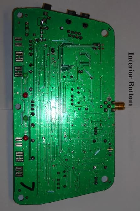
O9GWBASE
Oct 28, 2007WIRELESS MICROPHONE SYSTEM-BASE
Equipment Class
DXX - Part 15 Low Power Communication Device Transmitter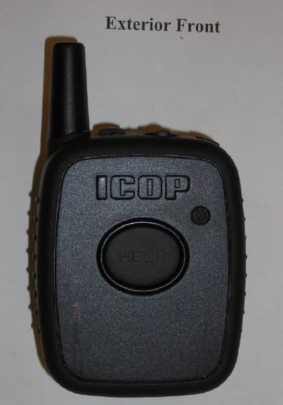
O9GWMIC
Oct 28, 2007MIC TRANSCEIVER
Equipment Class
DXX - Part 15 Low Power Communication Device Transmitter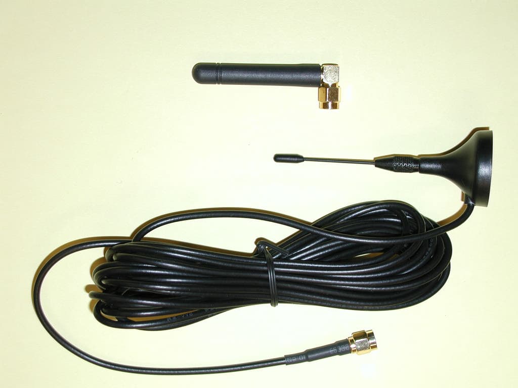
O9GDVMICT
Feb 05, 2006LOW POWER CAR TRANSCEIVER
Equipment Class
DXX - Part 15 Low Power Communication Device Transmitter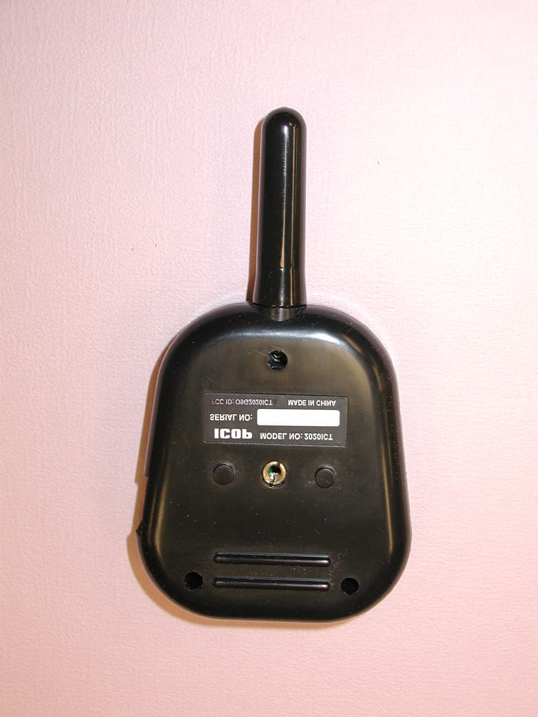
O9G2020ICT
May 02, 2005In Car Transceiver
Equipment Class
DXX - Part 15 Low Power Communication Device Transmitter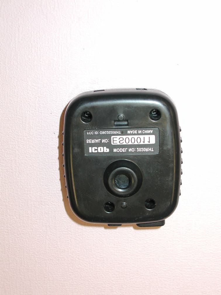
O9G2020RHT
May 01, 2005Remote Transceiver
Equipment Class
DXX - Part 15 Low Power Communication Device Transmitter