OAVRRC001ASelf Learning Duplicator
Altrusty Enterprise Co Ltd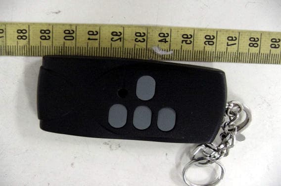
Click to zoom
Application Details
- Equipment Class
- DSC - Part 15 Security/Remote Control Transmitter
- Date of Grant
- Dec 11, 2005
- Application Purpose
- Original Equipment
- Date of Application
- Jun 20, 2005
- Equipment Note
- Self Learning Duplicator
- Frequency Range
- 390.00000000 - 390.00000000
- Company
- Altrusty Enterprise Co Ltd
- Country
- Taiwan
Documents & Files
Document Text
Text extracted from the exhibit documents filed with the FCC. Open a document above to read the original.
Users Manual
Created by Allremote Wireless Technology 2005/8/10 1 RRC001A Duplication Manual 1. Enter Duplication mode: Press Button 1 & Button 3 simultaneously and keeping pressing 1 & 3 buttons on the RRC001A, LED indicator will constantly flashing three times, and still hold these two buttons for 6 seconds, then LED indicator will flashing two times shortly. At this moment release both button then has into “enter duplication mode”. 2. Duplicate CODE: a. To make sure RRC001A in the “ enter duplication model ”, just pushed - still any key if LED indicator is flashing constantly that means in duplication mode. b. Place the Original one and next to RRC001A right side press it first, Then press the RRC001A which one you willing to define compare to the original one button quickly after the original one, It will flash 1 time shortly, (it duplicated successfully), what if LED keeps flashing (the duplicating failed), please repeat step b. 3. Duplicating Terminated: a. Press RRC001A Button 1 & Button 3 simultaneously, LED indicator flash once then goes off and you can use it. Created by Allremote Wireless Technology 2005/8/10 2 b. If duplicate failed, please repeat 1, 2, 3, step. c. The each buttons of RRC001A, can copy each individual variety code. In normal state, press down RRC001A any key, it will launch 300MHZ; 310MHZ and 390MHZ take turns in 3 frequency, if want to launch second time, have to release the button and start over again. A. For Genie Intellicode / GMI-3BL Garage Door Remote Controls (programming applicable to buttons 1, 2, 3 and 4) A 1. Entering Program Mode: Press the #1 and #3 buttons on the RRC001A simultaneously. You will notice a series of flashes from the RRC001A LED indicator: it will flash three times, stop, and then flash twice. You have now entered the Programming Mode. A 2. Programming RRC001A with Genie Intellicode / GMI-3BL Remote Transmitter: Place the RRC001A Press and hold button #1 (or any other buttons) on RRC001A and activate the button on the Source Remote. The LED indicator on the RRC001A will flash rapidly, then it will slow to a steady light. When the RRC001A has synchronized with the Source Remote, the LED indicator will go off. A 3. Exit Programming Mode: Again press the #1 and # 3 buttons on the RRC001A simultaneously. The LED indicator will flash once to confirm that you have exited the Programming Mode. Note: Especially for the well-known brand “Genie Intellicode/ GMI-3BL ” only product, Created by Allremote Wireless Technology 2005/8/10 3 RRC001A just can only be duplicated 2 individual remote codes. To the any 2 individual buttons on RRC001A . and the One original Genie Intelligent remote Code needs to be programmed into different buttons on either RRC001A . A 4. Programming RRC001A with the Genie Intellicode / GMI-3BL Garage Door Receiver: Aim the RRC001A close to the Receiver Unit in your garage. Press the button (learning actuator) on your Garage Door Receiver Unit, and it should begin flashing. Then press PRC001A any of programmed button, the receiver LED indicator will light on still, then pressing again the sample button, the receiver indicator will go out. It means programming completely. (Note: In certain instances, this procedure may cause the Genie Intellicod /GMI-3BL Remote to "unlearn" the programming. Make sure to check the Genie Intellicode /GMI-3BL Remote when finished, and re-program according to the manufacturer's Instructions if necessary. Then check both units to make sure that they operate the garage door opener properly.) A 5. Repeat steps A1 through A4 to program the second button for a second door opener. COMPATIBILITY CHART: REPLACEMENT BRAND IN USE SINCE TRANSMISSION (APPROX. YEAR) FREQUENCY Chamberlain 1983 390 MHz Genie 1985 390 MHz Lift Master 1983 390 MHz Linear/Moor-O-Matic 1976 310 MHz Multi-Code 1976 300 MHz Sears 1983 390 MHz Stanley 1976 310 MHz Genie Code Rolling After 1998 390 MHz Genie Regular Code Before 1998 390 MHz FCC approved, ID No. OAVRRC001A Created by Allremote Wireless Technology 2005/8/10 4 Notice : The changes or modifications not expressly approved by the party responsible for compliance could void the user’s authority to operate the equipment. THIS DEVICE COMPLIES WITH PART 15 OF THE FCCRULES. OPERATIONS IS SUBJECT TO THE FOLLOWING TWO CONDITIONS: ( 1 ) THIS DEVICE MAY NOT CAUSE HARMFUL INTERFERENCE AND ( 2 ) THIS DEVICE MUST ACCEPT ANY INTERFERENCE RECEIVED, INCLUDING INTERFEERENCE THAT MAY CAUSE UNDESRIED OPERATION.
Cover Letter(s)
Dear Diane, 1. The revised user manual has been submitted. 2. Please refer to the revised internal photos. Y2, Y3 and Y4 are on the solder side of the main PCB. 3. SW1, SW2, SW3 and SW4 are buttons which the user can control this device. This device can duplicate up to four control function codes from the original transmitter. The duplicate procedure and operation method are provided in the user manual. Best regards, S. S. Liou Engineer / EMC Dept. II Electronics Testing Center, Taiwan ----- Original Message ----- From: "Generic Office of Engineering Technology" <[email protected] > To: <[email protected]> Sent: Friday, July 29, 2005 12:15 AM Subject: FCC Equipment Authorization System > To: S.S. Liou, ELECTRONICS TESTING CENTER, TAIWAN > From: Diane Poole > [email protected] > FCC Application Processing Branch > > Re: FCC ID OAVRRC001A > Applicant: Altrusty Enterprise Co Ltd > Correspondence Reference Number: 29291 > 731 Confirmation Number: EA613105 > > > 1. Please submit the User Instructional manual indicating operation frequencies of this device. > 2. Please submit the picture of intentional circuitry showing operation frequency and jumpers. > 3. Please explain the function of the SW1, SW2, SW3 and SW4 in the Schematics diagram. > > > > > The items indicated above must be submitted before processing can continue on the above referenced application. Failure to provide the requested information within 60 days of the original e-mail date may result in application dismissal pursuant to Section 2.917 (c) and forfeiture of the filing fee pursuant to section 1.1108. > > DO NOT reply to this e-mail by using the Reply button. In order for your response to be processed expeditiously, you must upload your response via the Internet at www.fcc.gov, Electronic Filing, OET Equipment Authorization Electronic Filing. If the response is submitted through Add Attachments, in order to expedite processing, a message which informs the processing staff that a new exhibit has been submitted must also be submitted via Submit Correspondence. Also, please note that partial responses increase processing time and should not be submitted. > > Any questions about the content of this correspondence should be directed to the e-mail address listed below the name of the sender. >
External Photos
ETC Report No.:ET94R-06-050 FCC ID.: OAVRRC001A Rev. No 1.0 CONSTRUCTED PHOTOS of EUT Top View of EUT Bottom View of EUT ETC Report No.:ET94R-06-050 FCC ID.: OAVRRC001A Rev. No 1.0 CONSTRUCTED PHOTOS of EUT Front View of EUT Rear View of EUT
ID Label/Location Info
Model : RRC001A FCC ID : OVARRC001A 27 mm 12 mm Label Here
Internal Photos
ETC Report No.:ET94R-06-050 FCC ID.: OAVRRC001A Rev. No 1.0 CONSTRUCTED PHOTOS of EUT Internal View of EUT ETC Report No.:ET94R-06-050 FCC ID.: OAVRRC001A Rev. No 1.0 CONSTRUCTED PHOTOS of EUT Component View of Main PCB Solder View of Main PCB
Operational Description
This device is a learning transmitter of remote controller. The rated working frequencies are 300 MHz; 310 MHz and 390 MHz.
Test Report
Rev. No 1.0 FCC Part 15 EMI TEST REPORT of E.U.T. : Self Learning Duplicator FCC ID. : OAVRRC001A Model : RRC001A Working Frequency : 300 MHz; 310 MHz; 390 MHz for APPLICANT : ALTRUSTY ENTERPRISE CO., LTD. ADDRESS : 4F, No. 3, Alley 16, Lane 235, Bau Chiau Rd., Hsin- Tien City 231, Taipei Hsien, Taiwan, R.O.C. Test Performed by ELECTRONICS TESTING CENTER, TAIWAN NO. 34, LIN 5, DING FU TSUN, LINKOU HSIANG TAIPEI HSIEN, TAIWAN, R.O.C. Tel : (02)26023052 Fax : (02)26010910 http://www.etc.org.tw ; e-mail : [email protected] Report Number : ET94R-06-050 ETC Report No.:ET94R-06-050 FCC ID.: OAVRRC001A Rev. No 1.0 TEST REPORT CERTIFICATION Applicant : ALTRUSTY ENTERPRISE CO., LTD. 4F, No. 3, Alley 16, Lane 235, Bau Chiau Rd., Hsin-Tien City 231, Taipei Hsien, Taiwan, R.O.C. Manufacture : ALTRUSTY ENTERPRISE CO., LTD. 4F, No. 3, Alley 16, Lane 235, Bau Chiau Rd., Hsin-Tien City 231, Taipei Hsien, Taiwan, R.O.C. Description of EUT : a) Type of EUT : Self Learning Duplicator b) Trade Name : ALLREMOTE c) FCC ID : OAVRRC001A d) Model No. : RRC001A e) Working Frequency : 300 MHz; 310 MHz; 390 MHz f) Power Supply : DC 12V Battery Regulation Applied : FCC Rules and Regulations Part 15 Subpart C (2005) I HEREBY CERTIFY THAT; The data shown in this report were made in accordance with the procedures given in ANSI C63.4 and the energy emitted by the device was founded to be within the limits applicable. I assume full responsibility for accuracy and completeness of these data. Note : 1. The results of the testing report relate only to the items tested. 2. The testing report shall not be reproduced except in full, without the written approval of ETC. Issued Date : Jun. 15, 2005 Test Engineer : ( Kevin Lee ) Approve & Authorized Signer : Will Yauo, Manager EMC Dept. II of ELECTRONICS TESTING CENTER, TAIWAN ETC Report No.:ET94R-06-050 FCC ID.: OAVRRC001A Rev. No 1.0 Table of Contents Page 1. GENERAL INFORMATION...............................................................................................................................1 1.1 PRODUCT DESCRIPTION..........................................................................................................................................1 1.2 CHARACTERISTICS OF DEVICE:...............................................................................................................................1 1.3 TEST METHODOLOGY.............................................................................................................................................1 1.4 TEST FACILITY........................................................................................................................................................1 2. DEFINITION AND LIMITS.................................................................................................................................2 2.1 DEFINITION.............................................................................................................................................................2 2.2 RESTRICTED BANDS OF OPERATION........................................................................................................................2 2.3 LIMITATION.............................................................................................................................................................2 2.4 LABELING REQUIREMENT.......................................................................................................................................4 2.5 USER INFORMATION................................................................................................................................................4 3 SYSTEM TEST CONFIGURATION....................................................................................................................5 3.1 JUSTIFICATION.........................................................................................................................................................5 3.2 DEVICES FOR TESTED SYSTEM................................................................................................................................5 4. RADIATED EMISSION MEASUREMENT.......................................................................................................6 4.1 APPLICABLE STANDARD..........................................................................................................................................6 4.2 MEASUREMENT PROCEDURE..................................................................................................................................6 4.3 TEST DATA.............................................................................................................................................................8 4.3.1 Fundanmental and Harmonics........................................................................................................................8 4.3.2 Other Emission..............................................................................................................................................17 4.4 FIELD STRENGTH CALCULATION...........................................................................................................................26 4.5 ACTIVATE TIME....................................................................................................................................................26 4.6 CALCULATION OF DUTY FACTOR..........................................................................................................................26 4.7 RADIATED TEST EQUIPMENT.................................................................................................................................55 4.8 MEASURING INSTRUMENT SETUP..........................................................................................................................55 4.9 RADIATED MEASUREMENT PHOTOS..................................................................…
Text truncated - open the document above for the full version.
Test Setup Photos
ETC Report No.:ET94R-06-050 FCC ID.: OAVRRC001A Rev. No 1.0 Radiated Measurement Photos
Contact Information
Applicant
Wang Mao-Shen(General Manager)
Technical Contact
ELECTRONICS TESTING CENTER, TAIWANS.S. Liou
[email protected]886-2-26023052
NO. 34, LIN 5, DING FU TSUN, · TAIPEI HSIEN, · Taiwan
Non-Technical Contact
ELECTRONICS TESTING CENTER, TAIWANIris Lin
[email protected]886-2-26023052
Test Firm
Electronics Testing Center, TaiwanWill Yauo
Technical Specifications
| # | Rule Parts | Frequency Range | Power Output |
|---|---|---|---|
| 3 | 15.231 | 390 MHz - 390 MHz | - |
Other Applications from Altrusty Enterprise Co Ltd
OAVTXSL016
Apr 28, 2020Wireless Remote Control for Searchlight
Equipment Class
DXX - Part 15 Low Power Communication Device Transmitter
OAVTXSL010
Jul 22, 2007Remote Control
Equipment Class
DSC - Part 15 Security/Remote Control Transmitter
OAVTXSL011
Jul 22, 2007Remote Control
Equipment Class
DSC - Part 15 Security/Remote Control Transmitter
OAVTXSL003
Apr 19, 2007Remote Control Transmitter
Equipment Class
DSC - Part 15 Security/Remote Control Transmitter
OAVRRC065A
Jan 22, 2007Remote Control
Equipment Class
DSC - Part 15 Security/Remote Control Transmitter