OAYSRR6BSRD for RTTT and other vehicle or fixed installation
Automotive Distance Control Systems GmbHApplication Details
- Equipment Class
- VRD - Part 95 Vehicular Radar Systems
- Date of Grant
- May 20, 2026
- Application Purpose
- Original Equipment
- Equipment Note
- SRD for RTTT and other vehicle or fixed installation
- Frequency Range
- 76000.00000000 - 77000.00000000
- Country
- Germany
Documents & Files
Document Text
Text extracted from the exhibit documents filed with the FCC. Open a document above to read the original.
Cover Letter(s)
Autonomous and Commercial Mobilitiy SRR6-B Exhibit8 -AntennaInformation © AUMOVIO SE General Description of Antenna: 08.04.20262 Principle of Antenna implementation The antenna is designed to operate in the 76–77GHz and 77–81GHz frequency bands, supporting the corresponding operating modes. It is an integrated one component waveguide antenna comprising four transmit (Tx) and four receive (Rx) antenna elements, distributed across the antenna aperture. All four Tx antennas transmit simultaneously, generating a constant electromagnetic field. The Rx channels process the received signals to determine the angular direction of detected objects. Angular separation is achieved by applying signal coding across the transmit channels. The antenna’s main beam is directed perpendicular to the center of the antenna surface.
ID Label/Location Info
Autonomous and Commercial Mobility SRR6-B Exhibit 7 –Label © AUMOVIO SE SRR6-BLabel / Label Placement 226.03.2026
RF Exposure Info
© cetecom advanced GmbH Page 1 of 27 TEST REPORT Test Report No.: 1-0249-25-01-02_TR1-R01 Testing Laboratory Applicant cetecom advanced GmbH Untertuerkheimer Strasse 6 – 10 66117 Saarbruecken / Germany Phone: + 49 681 5 98 - 0 Fax: + 49 681 5 98 - 9075 Internet: https://cetecomadvanced.com e-mail: [email protected] Accredited Testing Laboratory: The testing laboratory (area of testing) is accredited according to DIN EN ISO/IEC 17025 (2018-03) by the Deutsche Akkreditierungsstelle GmbH (DAkkS). The accreditation is valid for the scope of testing procedures as stated in the accreditation certificate with the registration number: D-PL-12047-01-00. ISED Testing Laboratory Recognized Listing Number: DE0001 FCC designation number: DE0002 ADC Automotive Distance Control Systems GmbH Peter-Dornier-Str. 10 88131 Lindau / GERMANY Contact: Reitmayer Thomas e-mail: [email protected] Phone: +49 (0) 731 55035-3332 Manufacturer ADC Automotive Distance Control Systems GmbH Peter-Dornier-Str. 10 88131 Lindau / GERMANY Test Standard/s KDB 447498D01v06 Mobile and Portable Devices RF Exposure Procedures and Equipment Authorization Policies KDB 680106 D01v04 Equipment Authorization of Wireless Power Transfer devices IEC/IEEE 63195 ED1 Measurement Procedure for the assessment of power density of human exposure to radio frequency fields from wireless devices operating in close proximity to the head and body – Frequency range of 6 GHz to 300 GHz For further applied test standards please refer to section 3 of this test report. Test Item Kind of test item: SRD for RTTT and other vehicle or fixed installation Model name: SRR6-B FCC ID: OAYSRR6B Serial number: A2C782065160000224A0200032 (DUT 21) Frequency: 76 to 77 GHz 77 to 81 GHz Antenna: Integrated patch antenna Power supply: 9 V to 18 V DC by external power supply (battery) Test sample status: identical prototype Exposure category: general population / uncontrolled environment This test report is electronically signed and valid without handwritten signature. For verification of the electronic signatures, the public keys can be requested at the testing laboratory. Test Report authorised: Test performed: Alexander Hnatovskiy Marco Scigliano Lab Manager Testing Manager Radio Lab Radio Lab Test report no.: 1-0249-25-01-02_TR1-R01 © cetecom advanced GmbH Page 2 of 27 1 Table of contents 1 Table of contents ....................................................................................................................................... 2 2 General information .................................................................................................................................. 3 2.1 Notes and disclaimer ..................................................................................................................... 3 2.2 Application details ......................................................................................................................... 3 2.3 Statement of compliance ............................................................................................................... 3 3 Test standard/s: ......................................................................................................................................... 4 3.1 Maximum Permissible exposure limits according CFR 47 – Part 1, §1.1310 ........................... 4 4 Reporting statements of conformity – decision rule ............................................................................. 5 5 Summary of Measurement Results ......................................................................................................... 5 6 Test Environment ...................................................................................................................................... 5 7 Test Set-up ................................................................................................................................................. 6 7.1 Measurement system ..................................................................................................................... 6 7.1.1 System Description ................................................................................................................ 6 7.1.1.1 Workflow for Power Density Compliance Testing ................................................................. 7 7.1.1.2 Compatibility with IEC/IEEE 63195-1 ........................................................................................ 7 7.1.1.3 Probe description .................................................................................................................. 8 7.1.1.4 Phantom Description ............................................................................................................. 9 7.1.1.5 mmWave Device Holder (mmWDH) .................................................................................... 10 7.1.2 Scanning procedure ............................................................................................................ 10 7.1.3 mmWave Verification and Validation Sources .................................................................... 11 7.1.4 Uncertainties ........................................................................................................................ 12 7.1.5 Measurement uncertainty evaluation for SAR test .............................................................. 12 7.1.6 Measurement uncertainty evaluation for System Check ..................................................... 14 7.1.6.1 System Check ..................................................................................................................... 16 7.2 Test results ................................................................................................................................... 16 8 Test equipment and ancillaries used for tests ..................................................................................... 17 9 Observatio…
Text truncated - open the document above for the full version.
Test Report
TEST REPORT Test report no.: 1-8315-24-02-04_TR1-R01 Testing laboratory Applicant cetecom advanced GmbH Untertuerkheimer Strasse 6 – 10 66117 Saarbruecken / Germany Phone: + 49 681 5 98 - 0 Fax: + 49 681 5 98 - 9075 Internet: https://www.cetecomadvanced.com e-mail: [email protected] Accredited Testing Laboratory: The testing laboratory (area of testing) is accredited according to DIN EN ISO/IEC 17025 (2018-03) by the Deutsche Akkreditierungsstelle GmbH (DAkkS). The accreditation is valid for the scope of testing procedures as stated in the accreditation certificate with the registration number: D-PL-12047-01-00. ISED Testing Laboratory Recognized Listing Number: DE0001 FCC designation number: DE0002 ADC Automotive Distance Control Systems GmbH Peter-Dornier-Str. 10 88131 Lindau / GERMANY Phone: +49 8382 9699 - 0 Contact: Thomas Reitmayer e-mail: Thomas.Reitmayer@continental- corporation.com Phone: +49 731 55035-3332 Manufacturer ADC Automotive Distance Control Systems GmbH Peter-Dornier-Str. 10 88131 Lindau / GERMANY Test standard/s FCC - Title 47 CFR Part 95 FCC - Title 47 of the Code of Federal Regulations; Chapter I; Part 95 - Personal Radio Services For further applied test standards please refer to section 3 of this test report. Test Item Kind of test item: SRD for RTTT and other vehicle or fixed installation Model name: SRR6-B FCC ID: OAYSRR6B Frequency: 76.5 GHz band (76 GHz – 77 GHz) 79.0 GHz band (77 GHz – 81 GHz) Technology tested: FMCW Antenna: Integrated antenna Power supply: 6.5 V to 19 V DC by external power supply Temperature range: -40 °C to 85 °C This test report is electronically signed and valid without handwritten signature. For verification of the electronic signatures, the public keys can be requested at the testing laboratory. Test report authorized: Test performed: Thomas Vogler Sébastien Engelhardt Lab Manager Testing Manager Radio Labs Radio Labs Test report no.: 1-8315-24-02-04_TR1-R01 © cetecom advanced GmbH Page 2 of 81 1 Table of contents 1 Table of contents ........................................................................................................................................... 2 2 General information ....................................................................................................................................... 4 2.1 Notes and disclaimer ...................................................................................................................... 4 2.2 Application details .......................................................................................................................... 4 2.3 Involved test locations .................................................................................................................... 5 2.4 Test laboratories sub-contracted .................................................................................................... 5 2.5 Laboratory listings and recognitions ............................................................................................... 5 3 Test standard/s, references and accreditations ............................................................................................. 6 4 Reporting statements of conformity – decision rule ...................................................................................... 7 5 Test environment........................................................................................................................................... 8 6 Test item ....................................................................................................................................................... 8 6.1 General description ......................................................................................................................... 8 6.2 Additional information .................................................................................................................... 9 7 Description of the test setup ........................................................................................................................ 10 7.1 Shielded semi anechoic chamber .................................................................................................. 11 7.2 Shielded fully anechoic chamber ................................................................................................... 13 7.3 Radiated measurements > 18 GHz ................................................................................................ 15 7.4 Radiated measurements > 50/85 GHz ........................................................................................... 15 8 Sequence of testing ..................................................................................................................................... 17 8.1 Sequence of testing radiated spurious 9 kHz to 30 MHz ............................................................... 17 8.2 Sequence of testing radiated spurious 30 MHz to 1 GHz ............................................................... 18 8.3 Sequence of testing radiated spurious 1 GHz to 18 GHz ............................................................... 19 8.4 Sequence of testing radiated spurious above 18 GHz.................................................................... 20 8.5 Sequence of testing radiated spurious above 50 GHz with external mixers ................................... 21 9 Measurement uncertainty ............................................................................................................................ 22 10 Far field consideration for measurements above 18 GHz ........................................................................... 23 11 76.5 GHz Band (76 GHz – 77 GHz) ............................................................................................................. 24 11.1 Summary of measurement results ...........................................................................................…
Text truncated - open the document above for the full version.
Contact Information
Applicant
Thomas Reitmayer(Technical Expert)
[email protected]Fax: 00498382969919
Technical Contact
AUMOVIO Autonomous and Commercial Mobility US, LLCRobert Cavanagh
One Continental Drive · Auburn Hills, Michigan, 48326 · United States
Test Firm
cetecom advanced GmbHGerald Schmidt
[email protected]Fax: 49-681-598-8775
Technical Specifications
| # | Rule Parts | Frequency Range | Power Output | Emission |
|---|---|---|---|---|
| 1 | 95M | 76.00 GHz - 77.00 GHz | 258.00 mW | 934MF3N |
| 2 | 95M | 77.00 GHz - 81.00 GHz | 108.00 mW | 3G87F3N |
Other Applications from Automotive Distance Control Systems GmbH
OAYARS6B
Sep 01, 2026SRD for RTTT and other vehicle or fixed installation
Equipment Class
VRD - Part 95 Vehicular Radar Systems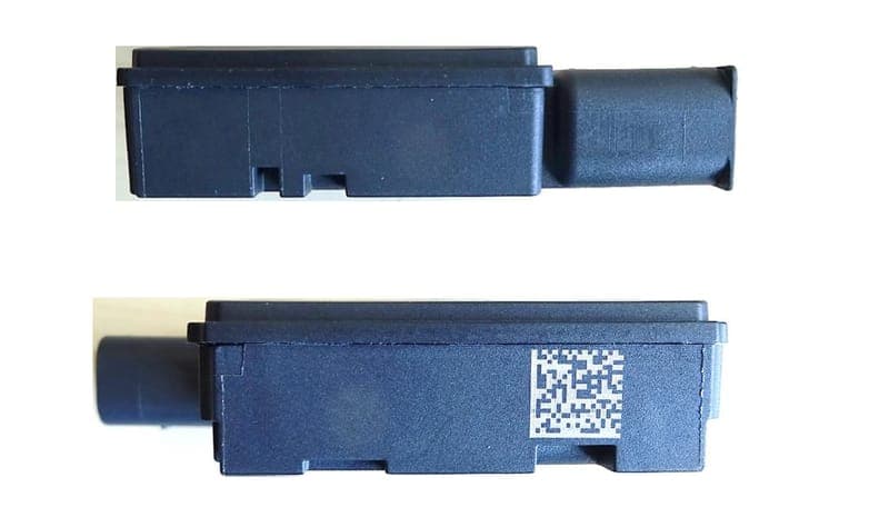
OAYSRR6A
Oct 03, 2023SRD for RTTT and other vehicle or fixed installation
Equipment Class
VRD - Part 95 Vehicular Radar Systems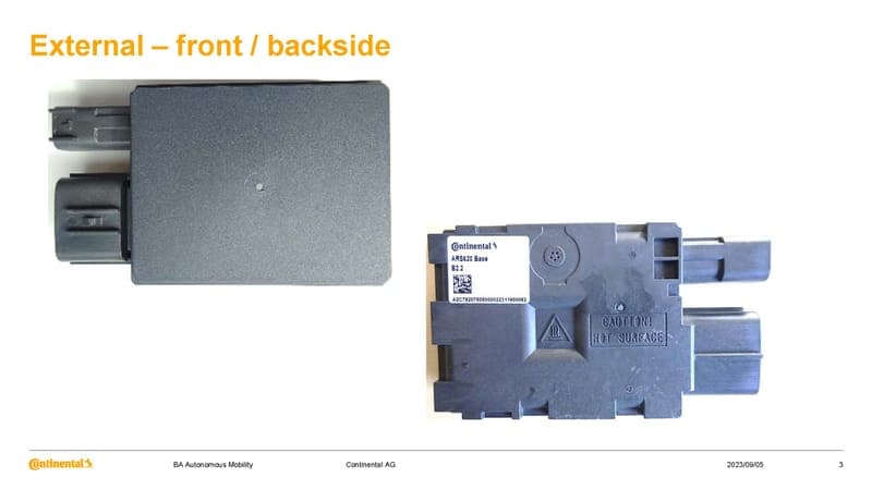
OAYARS6A
Sep 19, 2023SRD for RTTT and other vehicle or fixed installation
Equipment Class
VRD - Part 95 Vehicular Radar Systems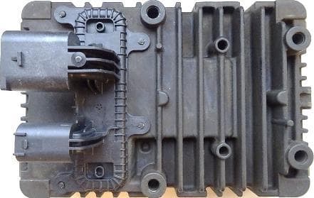
OAYARS5A
Dec 17, 2020SRD for RTTT and other vehicle or fixed installation
Equipment Class
VRD - Part 95 Vehicular Radar Systems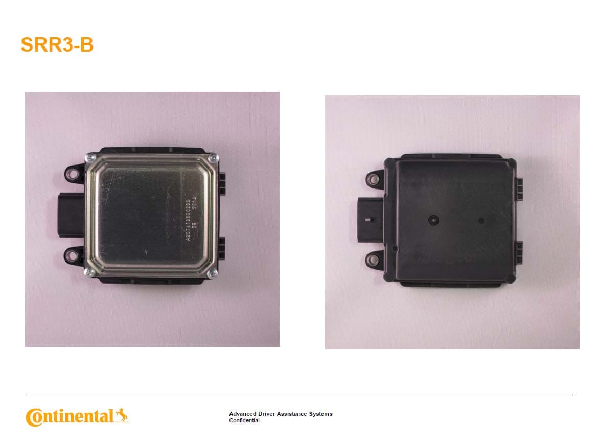
OAYSRR3B
Feb 11, 2015Advanced Driver Assistance Systems
Equipment Class
DXX - Part 15 Low Power Communication Device Transmitter