OB6-IGIU125PUProgramming Unit
Hi-G-Tek Ltd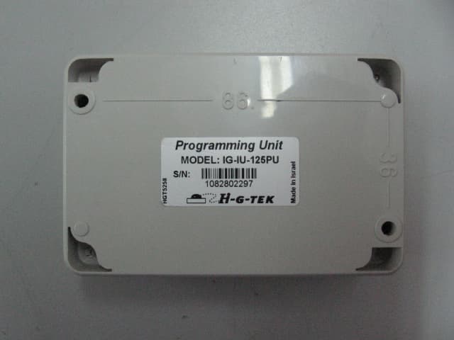
Click to zoom
Application Details
- Equipment Class
- DCD - Part 15 Low Power Transmitter Below 1705 kHz
- Date of Grant
- May 30, 2007
- Application Purpose
- Original Equipment
- Date of Application
- May 28, 2007
- Equipment Note
- Programming Unit
- Frequency Range
- 0.12500000 - 0.12500000
- Company
- Hi-G-Tek Ltd
- Country
- Israel
Documents & Files
Document Text
Text extracted from the exhibit documents filed with the FCC. Open a document above to read the original.
Users Manual
UM4728 Rev. 2.0 Programming Unit IG-IU-125PU -User Manual- 1. Introduction The Programming Unit is a desktop device that is used to configure the sensors prior to distribution or installation. The Programming Unit communicates with the sensors via the low frequency channel (125 KHz). It is externally powered and has RS232 channel to communicate with a PC. The Programming Unit is supplied with configuration software, which allows reading or writing parameters to the electronic sensor. 2. Warnings and Cautions • The Programming Unit required to be connected to a certified power source. In which the 9VDC output was evaluated as a Limited power source according to UL60950-1 standard 2.5. • To avoid damaging, please follow the installation instructions under the written order. The FCC Wants You to Know This equipment (FCC ID: OB6-IGIU125PU) has been tested and found to comply with the limits for a Class B digital device, pursuant to Part 15 of the FCC rules. These limits are designed to provide reasonable protection against harmful interference in a residential installation. This device complies with Part 15 of FCC rules. Operation is subject to the following two conditions: (1) This device may not cause harmful interference, and (2) This device must accept any interference that may cause undesired operation. This equipment generates uses and can radiate radio frequency energy and, if not installed and used in accordance with the instructions, may cause harmful interference to radio communications. However, there is no guarantee that interference will not occur in a particular installation. If this equipment does cause harmful interference to radio or television reception, which can be determined by turning the equipment off and on, the user is encouraged to try to correct the interference by one or more of the following measures: a) Reorient or relocate the receiving antenna. b) Increase the separation between the equipment and receiver. c) Connect the equipment to an outlet on a circuit different from that to which the receiver is connected. d) Consult the dealer or an experienced radio/TV technician. FCC Warning Modifications not expressly approved by the manufacturer could void the user authority to operate the equipment under FCC Rules. Instructions concerning human exposure to radio frequency electromagnetic fields: A distance of at least 20cm. between the equipment and all persons should be maintained during the operation of the equipment. 3. Installation Instructions 3.1 Connect DB9 male connector to Programming Unit side. 3.2 Connect DB9 female connector (with power cable) to PC side (COM port). 3.3 Plug in the AC/DC power adapter into the wall power outlet. 3.4 Place the electronic seal / tag up to 10cm from the Programming Unit. 3.5 Use provided Low Frequency communication software to communicate with the electronic seal / tag.
Block Diagram
μP 32K EEPROM Power Management AC/DC Adaptor 12VDC RS232 Driver DB9-RS232 Connector LF Transceiver TO PC LF OUT LF IN ANT 1 Ferrite LF Ant . 125 KHz Y1 8MHz RF Receive Interface RF Transmit Interface
Cover Letter(s)
March 28, 2007 Attn: Federal Communications Commission Authorization and Evaluation Division Confidentiality Request regarding application for certification of FCC ID: OB6-IGIU125PU Dear Sir or Ma'am, Pursuant to Sections 0.457 and 0.459 of the Commission’s Rules, we hereby request confidential treatment of information accompanying this application as outlined below: • IG-IU-125PU Assembly Confidential Schem.pdf • IG-IU-125PU Electrical Confidential Schem.pdf • IG-IU-125PU Confidential PartsLst.pdf The above materials contain trade secrets and proprietary information not customarily released to the public. The public disclosure of these materials may be harmful to the applicant and provide unjustified benefits to its competitors. Hi-G-Tek Ltd. understands that pursuant to Section 0.457 of the Rules, disclosure of this application and all accompanying documentation will not be made before the date of the Grant for this application.
External Photos
External Photographs of Tested E.U.T. Figure 1 Front View Figure 2 Rear View Figure 3 Data Port
Internal Photos
Internal Photographs of Tested E.U.T. Figure 1 PCB in Cover Figure 2 PCB Print Side Figure 3 PCB Component Side
Operational Description
Theory of Operation Circuit Description 1. Functional Description The Programming unit uses its simple 125kHz LF transceiver (at any time when it commanded to do so) to communicate by short range link with the end devices (active RFID electronic sensors) The data is transferred to the user through a serial RS-232 PC port. 2. Hardware Description 2.1. The PCB includes digital parts (μP, memory, RS232 driver etc.) and LF transceiver which utilizes on-off keying (OOK) modulation over a 125KHz carrier (4Kbit data rate) at short range (up to 20cm)
Test Report
Cert. No. 1152.01 Electrical (EMC) Test Report E70322.00 Hi-G-Tek Ltd. Page 1 of 41 ITL FCCMASVE 1.25 26 March 2003 DATE: 17 May 2007 I.T.L. (PRODUCT TESTING) LTD. FCC EMC/Radio Test for Hi-G-Tek Ltd. Equipment under test: Programming Unit* * See customer’s declaration on page 5. IG-IU-125PU Written by: _____________________________ D. Shidlowsky, Documentation Approved by: _____________________________ E. Pitt, Test Engineer Approved by: _____________________________ I. Raz, EMC Laboratory Manager This report must not be reproduced, except in full, without the written permission of I.T.L. (Product Testing) Ltd. This report relates only to items tested. Cert. No. 1152.01 Electrical (EMC) Test Report E70322.00 Hi-G-Tek Ltd. Page 2 of 41 ITL FCCMASVE 1.25 26 March 2003 Measurement/Technical Report for Hi-G-Tek Ltd. Programming Unit* *See customer’s declaration on page 5. IG-IU-125PU FCC ID: OB6-IGIU125PU 17 May 2007 This report concerns: Original Grant x Class II change Class B verification Class A verification Class I change Equipment type: Low Power Transmitter Below 1705kHz Request Issue of Grant: x Immediately upon completion of review Limits used: CISPR 22 Part 15 x Measurement procedure used is ANSI C63.4-2003. Application for Certification Applicant for this device: prepared by: (different from "prepared by") Ishaiahou Raz Yossi Hershko ITL (Product Testing) Ltd. Hi-G-Tek Ltd. 1 Batsheva St. P.O.B. 87 16 Hacharoshet St. Lod 71100 Or Yehuda 60375 Israel Israel Tel: +972-8-915-3100 Tel: +972-3-533-9359 Fax: +972-8-915-3101 Fax: +972-3-533-8225 Email: [email protected] Email: [email protected] Test Report E70322.00 Hi-G-Tek Ltd. Page 3 of 41 ITL FCCMASVE 1.25 26 March 2003 TABLE OF CONTENTS 1. GENERAL INFORMATION ------------------------------------------------------------------------------- 4 1.1 Administrative Information.................................................................................4 1.2 List of Accreditations .........................................................................................6 1.3 Product Description ...........................................................................................7 1.4 Test Methodology..............................................................................................8 1.5 Test Facility .......................................................................................................8 1.6 Measurement Uncertainty .................................................................................8 2. PRODUCT LABELING ------------------------------------------------------------------------------------ 9 3. SYSTEM TEST CONFIGURATION--------------------------------------------------------------------10 3.1 Justification......................................................................................................10 3.2 EUT Exercise Software ...................................................................................10 3.3 Special Accessories ........................................................................................10 3.4 Equipment Modifications .................................................................................10 3.5 Configuration of Tested System ......................................................................11 4. BLOCK DIAGRAM-----------------------------------------------------------------------------------------12 4.1 Schematic Block/Connection Diagram............................................................12 4.2 Theory of Operation ........................................................................................13 5. FIELD STRENGTH OF FUNDAMENTAL ------------------------------------------------------------14 5.1 Test Specification ............................................................................................14 5.2 Test Procedure................................................................................................14 5.3 Measured Data................................................................................................14 6. CONDUCTED AND RADIATED MEASUREMENT PHOTOS ----------------------------------16 7. CONDUCTED EMISSION DATA-----------------------------------------------------------------------18 7.1 Test Specification ............................................................................................18 7.2 Test Procedure................................................................................................18 7.3 Measured Data................................................................................................18 7.4 Test Instrumentation Used, Conducted Measurement ...................................23 8. RADIATED EMISSION, 9 KHZ – 30 MHZ -----------------------------------------------------------24 8.1 Test Specification ............................................................................................24 8.2 Test Procedure................................................................................................24 8.3 Measured Data................................................................................................24 8.4 Test Instrumentation Used, Radiated Measurements ....................................25 8.5 Field Strength Calculation ...............................................................................26 9. RADIATED EMISSION TEST DATA PER FCC PART 15, SUB-PART B -------------------27 9.1 Test Specification ............................................................................................27 9.2 Test Procedure................................................................................................27 9.3 Measured Data................................................................................................28 9.4 Test Instrumentation Used, Radiated Measurements ....................................33 9.5 Field Strength Calculation ...............................................................................34 10. PHOTOGRAPHS …
Text truncated - open the document above for the full version.
Test Setup Photos
Test set-up Photos Figure 1. Conducted Emission Test Front Figure 2. Conducted Emission Test Side Figure 3. Radiated Emission Test
Contact Information
Applicant
Roni Cohen(Hardware Department Manager)
Test Firm
Israel Testing LaboratoriesIIan Cohen
Technical Specifications
| # | Rule Parts | Frequency Range | Power Output |
|---|---|---|---|
| 1 | 15C | 0.125 MHz - 0.125 MHz | - |
Other Applications from Hi-G-Tek Ltd

OB6-IGSV40916
Dec 25, 2013SPDS SEAL
Equipment Class
DXX - Part 15 Low Power Communication Device Transmitter
OB6-IGST51433
Jan 18, 2010ISO 18000-7 SENSOR TRANSPONDER
Equipment Class
DSC - Part 15 Security/Remote Control Transmitter
OB6-IGST50433
Jan 18, 2010ISO 18000-7 SECURITY TRANSPONDER
Equipment Class
DSC - Part 15 Security/Remote Control Transmitter
OB6-IGRF97433
Jan 03, 2010ISO-18000- FIXED RFID INTERROGATOR
Equipment Class
DSR - Part 15 Remote Control/Security Device Transceiver
OB6-IGMA125IS
Feb 26, 2008IS Micro Reader
Equipment Class
DCD - Part 15 Low Power Transmitter Below 1705 kHz