OB6-IGMA125Micro Reader
Hi-G-Tek Ltd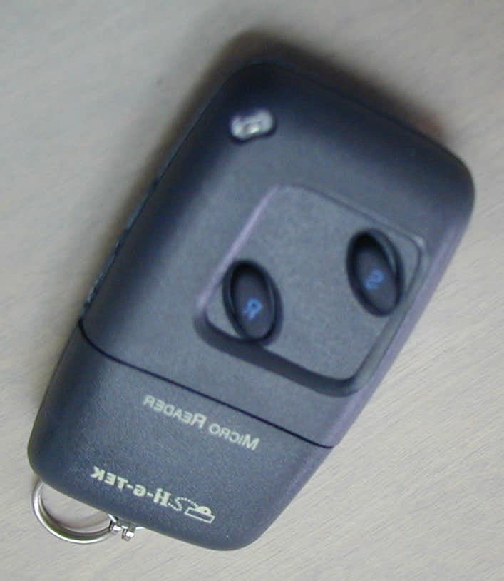
Click to zoom
Application Details
- Equipment Class
- DCD - Part 15 Low Power Transmitter Below 1705 kHz
- Date of Grant
- Aug 15, 2002
- Application Purpose
- Original Equipment
- Date of Application
- Aug 15, 2002
- Equipment Note
- Micro Reader
- Frequency Range
- 0.12500000 - 0.12500000
- Company
- Hi-G-Tek Ltd
- Country
- Israel
Documents & Files
Document Text
Text extracted from the exhibit documents filed with the FCC. Open a document above to read the original.
Users Manual
Micro Reader User Operating Instructions 1 Hi-G-Tek Ltd. Microelectronics & Asset Tracking Technology Micro Reader Maintenance: The only maintenance required, is to replace the battery when necessary. To replace the battery, open the battery compartment using medium size screwdriver ( Fig.4). Take out the old battery and put a fresh one (Fig. 5). Note polarity, as marked on the enclosure. Use 12V alkaline A23 battery. Close cover after installing the fresh battery. 4 Micro Reader Hi-G-Tek Ltd. Microelectronics & Asset Tracking Technology UM4707 Rev: 1.0 Fig. 4 ICR O ICR O E A D E R E A D E R M M RR Fig. 5 + - FCC ID: OB6-IGMA125 This device complies with Part 15 of FCC rules. Operation is subject to the following two conditions: (1) This device may not cause harmful interference, and (2) This device must accept any interference that may cause undesired operation. NOTE: This equipment has been tested and found to comply with the limits for a Class B digital device, pursuant to part 15 of the FCC Rules. These limits are designed to provide reasonable protection against harmful interference in a residential installation. This equipment generates, uses and can radiate radio frequency energy and, if not installed and used in accordance with the instructions, may cause harmful interference to radio communications. However, there is no guarantee that interference will not occur in a particular installation. If this equipment does cause harmful interference to radio or television reception, which can be determined by turning the equipment off and on, the user is encouraged to try to correct the interference by one or more of the following measures: -Reorient or relocate the receiving antenna. -Increase the separation between the equipment and receiver. -Connect the equipment into an outlet on a circuit different from that to which the receiver is connected. -Consult the dealer or an experienced radio/TV technician for help. Changes or modifications to this equipment not expressly approved by Hi-G-Tek Ltd. could void the user's authority to operate the equipment. The Micro Reader communicates with the DataSeal or the DataSeal-125 over the low frequency channel using 125KHz as the carrier. The Micro Reader is used for executing one or two functions, depending on the model: Micro Reader with READ only - Model: IG-MA-125 This device is used for checking the seal status. Approach the DataSeal as shown in Fig.2 to a distance of 3-8cm and press the R button. (Item 1 in Fig.1) In the event that the seal status is OK the LED (item 2 in Fig.1) will turn Green, and a corresponding “click” will sound. In the event that seal status is TAMPERED, the LED will turn Red and a corresponding “beep” will sound. In the event that the communication between the Micro Reader and the DataSeal failed, the Micro Reader will pause for two seconds and the LED will flash Red three times with corresponding three fast “clicks”. 2 Micro Reader Hi-G-Tek Ltd. Microelectronics & Asset Tracking Technology Micro Reader with SET option - Model: IG-MA-125S All instructions for checking the seal status are the same in both models. This model can also perform a “Soft Set”: setting the seal (OK status) without erasing the events logged in seal’s memory. To perform a “Soft Set”, approach the seal as shown in Fig.2, and press the S button (item 1 in Fig.3). In the event of successful “Soft Set”, the LED will turn Green and a corresponding “click” will sound. In the event that the “Soft Set” command failed, the Micro Reader will pause for two seconds, and then the LED will flash Red three times with corresponding three fast “clicks”. 3 Micro Reader Hi-G-Tek Ltd. Microelectronics & Asset Tracking Technology Fig. 1 21 1 Fig. 3 D a t a S e a l D a t a S e a l Fig. 2
Block Diagram
Micro Reader circuit description 1. General 1.1. Reference documents 1.1.1. Schematic , document 47C10050 1.2. Pages number referenced in the following description, are referred to the schematic. 2. General Description 2.1. The Micro Reader is part of a system which includes DataSeal. The DataSeal is used to electronically seal assets during storage or shipment. The Micro Reader is used to inspect DataSeal status. The Inspector presses a button, the Micro Reader wakes up, interrogate the DataSeal, and lights an LED according to seal status. RED means seal is tampered, GREEN means seal is OK. 2.2. The Micro Reader is a stand-alone unit. It has a replaceable battery , it has RF receiver and transmitter and microprocessor (ìP), which controls the Micro Reader operation. 2.3. The Micro Reader RF channel is 125KHz carrier with OOK modulated data. 3. Hardware Description 3.1. A PCB is mounted in pocket size enclosure, a replaceable battery 12V battery supplies power to the Micro Reader. The circuit includes micro controller, 4MHz crystal, E2ROM, power supply regulator ,125KHz transmitter and receiver. 4. Circuit description. 4.1. Block Diagram 4.2. ìP (U1 Pg.2): PIC16F876 ìP timed by an 4MHz ceramic resonator (Y1). 4.3. Buzzer (LS1 Pg.2): generates audible signal to indicate interrogation result. 4.4. E2ROM (U2 Pg.2): Serial E2ROM stores unit parameters and data. 4.5. Power management: (Pg.2): 12V A23 type battery powers the circuit. D2 used for reverse polarity protection. U3 regulate the voltage to the all circuit. On stand by, U3 is OFF and the circuit is not powered. When one of the switches (S1,S2) is pressed, U3 is enabled thus powering the circuit. The micro controller wakes up and hold the power by Q1, until cycle is finished. 4.6. LF Transmitter (Q2, Pg.3): OOK modulated data comes from the ìP to the driver transistor Q2, which drives a ferrite antenna (L1). 4.7. LF Receiver (C8 to U4 Pg.3): Data received in the ferrite antenna (L1), D7,D8,D9 and Q3 are used to limit signal amplitude. D6 used for envelope detection of the signal and data is digitized by U4. Q2 L 1 D5B VDD Modulated data from uP C5 C7,C8
Cover Letter(s)
July 17, 2002 American TCB 6731 Whittier Ave Suite C110 McLean, VA 22101 USA Subject: Request for confidentiality for Micro Reader, model IG-MA-125S, FCC ID: OB6-IGMA125 Dear Gentlemen, We apply to you with request to withhold Hi-G-Tek Ltd. trade secrets in Application for Certification for FCC ID: OB6-IGMA125. These trade secrets can be found in the transmitter schematic diagram (3 pages of this Application: Document number 47C10050). Many thanks in advance. Sincerely yours Mr. Micha Auerbach, President and CEO Hi-G-Tek Ltd.
Cover Letter(s)
American Telecommunications Certification Body Inc. 6731 Whittier Ave, McLean, VA 22101 August 12, 2002 RE: Hi-G-Tek Ltd. FCC ID: OB6-IGMA125 After a review of the submitted information, I have a few comments on the above referenced Application. 1) Please provide a block diagram for the 125 kHz TX portion of the EUT. 2) Please explain the addition of 20 dB for correction factor as given on page 11 of 23. Note this didn't appear in application FCC ID: OB6-IGRS40916. Timothy R. Johnson Examining Engineer mailto: [email protected] The items indicated above must be submitted before processing can continue on the above referenced application. Failure to provide the requested information may result in application termination. Correspondence should be considered part of the permanent submission and may be viewed from the Internet after a Grant of Equipment Authorization is issued. Please do not respond to this correspondence using the email reply button. In order for your response to be processed expeditiously, you must submit your documents through the AmericanTCB.com website. Also, please note that partial responses increase processing time and should not be submitted. Any questions about the content of this correspondence should be directed to the sender.
Cover Letter(s)
FCC ID: OB6-IGMA125 In reply to e-mail dated August 11, 2002 Dear Mr. Johnson, Below are the answers to your questions. 1. Please find an updated block diagram in "Micro-reader circuit description.pdf", submitted via "Add to existing application", Block diagram folder on August 15, 2002. 2. It happened due to our oversight: during the last measurements with the same spectrum analyzer (for some other company) we used an amplifier (+20 dB), therefore a correction factor (-20 dB) was added automatically to the results. This setting remained unchanged when we performed field strength measurements for Dataseal 125 and microreader, though amplifier was not used. We noticed this mistake, and, instead of re-performing the measurements, added 20 dB to all measured results. FCC ID: OB6-IGSA125 In reply to e-mail dated August 11, 2002 Dear Mr. Johnson, Below are the answers to your questions. 1. Please find an updated block diagram in "DataSeal125 circuit description.pdf", submitted via "Add to existing application", Block diagram folder on August 15, 2002. 2. It happened due to our oversight: during the last measurements with the same spectrum analyzer (for some other company) we used an amplifier (+20 dB), therefore a correction factor (-20 dB) was added automatically to the results. This setting remained unchanged when we performed field strength measurements for Dataseal 125 and microreader, though amplifier was not used. We noticed this mistake, and, instead of re-performing the measurements, added 20 dB to all measured results. Hope, you find these answers satisfactory. With great respect, Natasha To: "'[email protected]'" <[email protected]> Subject: OB6-IGMA125 and OB6-IGSA125 applications Page 1 of 1In 8/16/2002Printed for "Timothy R. Johnson" <[email protected]>
External Photos
FCC ID:OB6-IGMA125 Date: July 2002 Page 1 of 3 EXTERNAL PHOTOGRAPHS This document contains 2 photographs FCC ID:OB6-IGMA125 Date: July 2002 Page 2 of 3 Photograph No.1 Micro Reader general view FCC ID:OB6-IGMA125 Date: July 2002 Page 3 of 3 Photograph No.2 Micro Reader rear view The correct label will be placed here.
ID Label/Location Info
FCC ID: OB6-IGMA125 Date: July 2002 Project number: 15025 Page 1 of 1 LABEL The label shown below is affixed on the bottom of the Micro Reader. The label dimensions are 25.50 x 12.70 (mm), material - PVC with a permanent adhesive. The manufacturer and EUT names are silk screened on the front panel of the Micro Reader. The FCC part 15, §15.105 statement is placed in User Manual, page 4. Label placement on the EUT bottom FCC ID: OB6-IGMA125 This device complies with Part 15 of the FCC Rules. Operation is subject to the following two conditions: (1) This device may not cause harmful interference, and (2) This device must accept any interference received, including interference that may cause undesired operation.
Internal Photos
FCC ID:OB6-IGMA125 Date: July 2002 Page 1 of 3 INTERNAL PHOTOGRAPHS This document contains 2 photographs FCC ID:OB6-IGMA125 Date: July 2002 Page 2 of 3 Photograph No.1 PCB component side FCC ID:OB6-IGMA125 Date: July 2002 Page 3 of 3 Photograph No.2 PCB printed side
Operational Description
Micro Reader description 1. General 1.1. Reference documents 1.1.1. Schematics, document number 47C10050 1.2. Page numbers referenced in the following description, are referred to the schematics. 2. General Description 2.1. Micro Reader and DataSeal-125 comprise a system. The DataSeal-125 is used to electronically seal assets during storage or shipment. The Micro Reader is used to inspect DataSeal-125 status. An inspector presses a button, the Micro Reader wakes up, interrogates the DataSeal-125 and lights a LED according to the seal status. RED means the seal is tampered; GREEN means the seal is OK. 2.2. The Micro Reader is a stand-alone unit. It has a replaceable battery, RF receiver, transmitter and microprocessor (μP), which controls the Micro Reader operation. 2.3. The Micro Reader RF channel is 125KHz carrier with OOK modulated data. 3. Hardware Description 3.1. A PCB is mounted in a pocket size enclosure; a replaceable 12V battery supplies power to the Micro Reader. The circuit includes micro controller, 4MHz crystal, E2ROM, power supply regulator, 125KHz transmitter and receiver. 4. Circuit description. 4.1. Block Diagram 4.2. μP (U1 Pg.2): PIC16F876 μP is timed by a 4MHz ceramic resonator (Y1). 4.3. Buzzer (LS1 Pg.2): generates audible signal to indicate interrogation result. 4.4. E2ROM (U2 Pg.2): Serial E2ROM stores unit parameters and data. 4.5. Power management: (Pg.2): 12V A23 type battery powers the circuit. D2 is used for reverse polarity protection. U3 regulates the voltage to the whole circuit. In stand by mode, U3 is OFF and the circuit is not powered. When one of the switches (S1, S2) is pressed, U3 is enabled thus powering the circuit. The micro controller wakes up and holds the power by Q1, until cycle is finished. 4.6. LF Transmitter (Q2, Pg.3): OOK modulated data comes from the μP to the driver transistor Q2, which drives a ferrite antenna (L1). 4.7. LF Receiver (C8 to U4 Pg.3): Data is received in the ferrite antenna (L1); D7, D8, D9 and Q3 are used to limit signal amplitude. D6 is used for envelope detection of the signal and data is digitized by U4.
Test Report
This report is in conformity with and ISO/IEC 17025. The A2LA logo endorsement applies only to the test methods and the standards that are listed in the scope of Hermon Laboratories accreditation. The test results relate only to the items tested. This test report must not be reproduced in any form except in full with the approval of Hermon Laboratories Ltd. Page 1 of 23 Document ID: HIGRAD_FCC.15025.doc Date of Issue: February 2002 HERMON LABORATORIES Electrical Hermon Laboratories Ltd. P.O.Box 23 Binyamina 30550, Israel Tel.+972 46288001 Fax.+972 46288277 e-mail: [email protected] ELECTROMAGNETIC EMISSION TEST REPORT ACCORDING TO 47CFR PART 15, SUBPART C § 15.209, 15.205 AND SUBPART B for Hi-G-Tek Ltd. EQUIPMENT UNDER TEST: Micro Reader Model IG-MA-125S Page 2 of 23 Document ID: HIGRAD_FCC.15025.doc Date of Issue: February 2002 HERMON LABORATORIES Hermon Laboratories Ltd. P.O.Box 23 Binyamina 30550, Israel Tel.+972 46288001 Fax.+972 46288277 e-mail: [email protected] Contents 1 PROJECT INFORMATION................................................................................................................................................................3 2 SUMMARY OF TESTS.......................................................................................................................................................................4 3 EUT DESCRIPTION............................................................................................................................................................................6 3.1 GENERAL DESCRIPTION..................................................................................................................................................................6 3.2 EUT TEST CONFIGURATION...........................................................................................................................................................6 3.3 TRANSMITTER DESCRIPTION...........................................................................................................................................................7 4 TESTS RESULTS...............................................................................................................................................................................8 4.1 FIELD STRENGTH OF EMISSION ACCORDING TO §15.209..............................................................................................................8 4.2 UNINTENTIONAL RADIATED EMISSIONS TEST ACCORDING TO §15.109..........................................................................................9 APPENDIX A PLOTS...............................................................................................................................................................................11 APPENDIX B TEST SETUP PHOTOGRAPHS...................................................................................................................................14 APPENDIX C TEST EQUIPMENT USED FOR TESTS.....................................................................................................................17 APPENDIX D GENERAL INFORMATION...........................................................................................................................................18 TEST FACILITY DESCRIPTION......................................................................................................................................................................18 ABBREVIATIONS AND ACRONYMS...............................................................................................................................................................18 SPECIFICATION REFERENCES....................................................................................................................................................................18 FCC EQUIPMENT CODES AND DESCRIPTIONS...........................................................................................................................................19 APPENDIX E TEST EQUIPMENT CORRECTION FACTORS.........................................................................................................20 Page 3 of 23 Document ID: HIGRAD_FCC.15025.doc Date of Issue: February 2002 HERMON LABORATORIES Hermon Laboratories Ltd. P.O.Box 23 Binyamina 30550, Israel Tel.+972 46288001 Fax.+972 46288277 e-mail: [email protected] 1 Project information Description of equipment under test Test items Micro Reader Manufacturer Hi-G-Tek Type (Model) IG-MA-125S Hardware revision A00 Software release 1.02 Serial number 1367343128 Equipment FCC code 1 DSR Applicant information Applicant’s responsible person Mr. Sharon Azran, Project Manager Company Hi-G-Tek Address 16 Haharoshet street, Postal code 60375 City Or-Yehuda Country Israel Telephone number +972 3 5331575 Telefax number +972 3 5339225 Test performance Project number: 15025 Location Hermon Laboratories Receipt date March 5, 2002 Test performed March 5, 2002 Purpose of test Apparatus compliance verification in accordance with emission requirements Test specifications 47CFR Part 15, §15.209, 15.205 and subpart B 1 FCC Equipment codes – see Appendix D Page 4 of 23 Document ID: HIGRAD_FCC.15025.doc Date of Issue: February 2002 HERMON LABORATORIES Hermon Laboratories Ltd. P.O.Box 23 Binyamina 30550, Israel Tel.+972 46288001 Fax.+972 46288277 e-mail: [email protected] 2 Summary of tests The tests listed in the table below were performed. The EUT was found complying with the limits of 47CFR Part 15, §15.209, 15.205 and subpart B. Parameter Subclause C NC NT NA Tested by Date tested Remarks Intentional radiation, §15.209 Field strength of emission (a) C Mr. Y. Neuman, test engineer March 5, 2002 Unintentional radiation, §15.107, §15.109 Conducted emissions 15.107 NA Radiated emissions 15.109 C Mr. Y. Neuman, test engineer March 5, 2002 NOTE: C: The parameter is compliant with the requirements. NC: The parameter is not …
Text truncated - open the document above for the full version.
Test Setup Photos
FCC ID:OB6-IGMA125 Date: July 2002 Page 1 of 4 TEST SETUP PHOTOGRAPHS This document contains 3 photographs FCC ID:OB6-IGMA125 Date: July 2002 Page 2 of 4 Photograph No.1 Radiated emission measurements test setup with loop antenna, 9 kHz – 30 MHz frequency range, anechoic chamber method FCC ID:OB6-IGMA125 Date: July 2002 Page 3 of 4 Photograph No.2 Radiated emission measurements test setup with biconilog antenna, 30 MHz – 1000 MHz frequency range, anechoic chamber method FCC ID:OB6-IGMA125 Date: July 2002 Page 4 of 4 Photograph No.3 Radiated emission measurements test setup, anechoic chamber method
Contact Information
Applicant
Roni Cohen(Hardware Department Manager)
Technical Contact
Hermon LaboratoriesGonen Usishkin
[email protected]972-4-628-8001
Harakevet Industrial Zone, P.O. Box 23 · Binyamina · Israel
Non-Technical Contact
Hi-G-Tek Ltd.Yossi Haimonvich
[email protected]972-3533-9359
Test Firm
Hermon Laboratories Ltd.Alexander Usoskin
Technical Specifications
| # | Rule Parts | Frequency Range | Power Output |
|---|---|---|---|
| 1 | 15C | 0.125 MHz - 0.125 MHz | - |
Other Applications from Hi-G-Tek Ltd

OB6-IGSV40916
Dec 25, 2013SPDS SEAL
Equipment Class
DXX - Part 15 Low Power Communication Device Transmitter
OB6-IGST51433
Jan 18, 2010ISO 18000-7 SENSOR TRANSPONDER
Equipment Class
DSC - Part 15 Security/Remote Control Transmitter
OB6-IGST50433
Jan 18, 2010ISO 18000-7 SECURITY TRANSPONDER
Equipment Class
DSC - Part 15 Security/Remote Control Transmitter
OB6-IGRF97433
Jan 03, 2010ISO-18000- FIXED RFID INTERROGATOR
Equipment Class
DSR - Part 15 Remote Control/Security Device Transceiver
OB6-IGMA125IS
Feb 26, 2008IS Micro Reader
Equipment Class
DCD - Part 15 Low Power Transmitter Below 1705 kHz