OEOTLSR8278DK48DTLSR8278DK48D
Telink Semiconductor (Shanghai) Co., Ltd.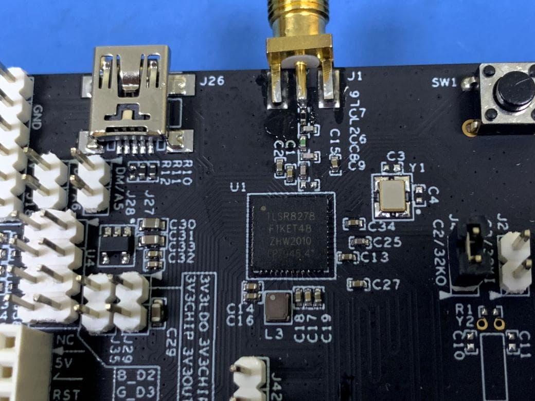
Click to zoom
Application Details
- Equipment Class
- DTS - Digital Transmission System
- Date of Grant
- May 28, 2020
- Application Purpose
- Original Equipment
- Date of Application
- May 27, 2020
- Equipment Note
- TLSR8278DK48D
- Frequency Range
- 2402.00000000 - 2480.00000000
- Country
- China
Documents & Files
Document Text
Text extracted from the exhibit documents filed with the FCC. Open a document above to read the original.
Users Manual
Telink Debug EVK TLSR8278DK48D User Manual TELINK SEMICONDUCTOR Keyword: Features; Pin connection; User manual Brief: This is a user manual for Telink 8278 Dongle. Telink Debug EVK TLSR8278DK48D User Manual 1 Published by Telink Semiconductor Bldg 3, 1500 Zuchongzhi Rd, Zhangjiang Hi-Tech Park, Shanghai, China © Telink Semiconductor All Right Reserved Legal Disclaimer This document is provided as-is. Telink Semiconductor reserves the right to make improvements without further notice to this document or any products herein. This document may contain technical inaccuracies or typographical errors. Telink Semiconductor disclaims any and all liability for any errors, inaccuracies or incompleteness contained herein. Copyright (c) 2019 Telink Semiconductor (Shanghai) Ltd, Co. Information: For further information on the technology, product and business term, please contact Telink Semiconductor Company (www.telink-semi.com). For sales or technical support, please send email to the address of: [email protected] [email protected] Telink Debug EVK TLSR8278DK48D User Manual 2 Table of contents 1 Product Introduction .............................................................................................. 3 1.1 General description .......................................................................................... 3 1.2 Key features ..................................................................................................... 3 2 Pin Connection Guide ............................................................................................. 3 2.1 Supply power ................................................................................................... 3 2.2 Download firmware ......................................................................................... 5 2.3 Test RF signal .................................................................................................... 6 Telink Debug EVK TLSR8278DK48D User Manual 3 1 Product Introduction This is a user manual for Telink Debug EVK TLSR8278DK48D. 1.1 General description The TLSR8278DK48D, which is based on Telink TLSR8278F1KET48 chip, provides a Bluetooth LE . The TLSR8278DK48D integrates a power-balanced 32-bit MCU, BLE, 64kB SRAM, 1MB internal Flash, 14bit ADC , 6-channel PWM, flexible GPIO interfaces, and nearly all the peripherals needed for IoT (Internet of Things) and HID (Human Interface Devices) application development (e.g. Bluetooth Low Energy . 1.2 Key features Bluetooth 5 Compliant, 1Mbps, 2Mbps, Long Range 125kbps and 500kbps 64kB on-chip SRAM with up to up to 32kB retention A rich set of I/Os: SPI, I2C, Single wire, up to 32 GPIOs, UART with hardware flow control and 7816 protocol support, DMIC (Digital Mic), AMIC (Analog Mic), I2S, Stereo Audio output 6-channel PWM (Pulse Width Modulation) output RSSI monitoring with +/-1dB resolution Power supply: DC3.3V 2 Pin Connection Guide 2.1 Supply power The TLSR8278DK48D supports supply power via battery or other 3.3V power. The power connection is shown below, connect the power to the 3V3 of J18, and Telink Debug EVK TLSR8278DK48D User Manual 4 connect the GND to the GND of J18. Figure 1 Connection chart to supply power 3V3 GND Telink Debug EVK TLSR8278DK48D User Manual 5 2.2 Download firmware To download firmware into TLSR8278DK48D, first make sure the TLSR8278DK48D is supplied with power normally. That is, connect the power to the 3V3 of J18, and connect the GND to the GND of J18. Then connect J18 (SWS) of the TLSR8278DK48D with SWM of a burning EVK. Meanwhile, connect the miniUSB interface of the burning EVK with PC USB. Figure 2 Connection chart to download firmware 3V3 SWS GND Telink Debug EVK TLSR8278DK48D User Manual 2.3 Test RF signal To test RF signal of TLSR8278DK48D, first make sure the TLSR8278DK48D is supplied with power normally. That is, connect the power to the 3V3 of J18, and connect the GND to the GND of J18. In conducted mode, connect SMA connector to spectrum analyzer, or other RF instruments. In radiated mode, connect SMA connector to external antenna. Figure 3 Connection chart to test RF signal SMA connector This device complies with Part 15 of the FCC rules. Operation is subject to the following two conditions: 1) this device may not cause harmful interference, and 2) this device must accept any interference received, including interference that may cause undesired operation. This equipment has been tested and found to comply with the limits for a Class B digital device, pursuant to Part 15 of the FCC rules. These limits are designed to provide reasonable protection against harmful interference in a residential installation. This equipment generates, uses and can radiate radio frequency energy and if not installed and used in accordance with the instructions, may cause harmful interference to radio communications. However, there is no guarantee that interference will not occur in a particular installation. If this equipment does cause harmful interference to radio or television reception, which can be determined by turning the equipment off and on, the user is encouraged to try correct the interference by one or more of the following measures: - Reorient the receiving antenna. - Increase the separation between the equipment and receiver. - Connect the equipment into and outlet on a circuit different from that to which the receiver is connected. - Consult the dealer or an experienced radio/TV technician for help. Changes or modifications not expressly approved by the party responsible for compliance could void your authority to operate the equipment.
External Photos
Model No.: TLSR8278DG48D
ID Label/Location Info
Model No: TLSR8278DK48D FCC ID:OEOTLSR8278DK48D Manufacture: Telink Semiconductor (Shanghai) Co., Ltd. Address: Bldg 3, No.1500, Zuchongzhi Rd, Zhangjiang Hi-Tech Park, Shanghai 201203, China Importer: XXX Address: XXX
Internal Photos
Model No.: TLSR8278DG48D
RF Exposure Info
RF Exposure Evaluation Statement Product Name: TLSR8278DK48D Model No.:TLSR8278DK48D FCC ID:OEOTLSR8278DK48D 1.1 RF Exposure Compliance Requirement 1.1.1 Standard Requirement According to KDB447498D01 General RF Exposure Guidance v06 Standalone SAR test exclusion considerations Unless specifically required by the published RF exposure KDB procedures, standalone 1-g head or body and 10-g extremity SAR evaluation for general population exposure conditions, by measurement or numerical simulation, is not required when the corresponding SAR Exclusion Threshold condition, listed below, is satisfied. 1.1.2 Limits The 1-g and 10-g SAR test exclusion thresholds for 100 MHz to 6 GHz at test separation distances ≤ 50 mm are determined by: [(max. power of channel, including tune-up tolerance, mW)/(min. test separation distance, mm)] · [√f(GHz)] ≤ 3.0 for 1-g SAR and ≤ 7.5 for 10-g extremity SAR, where f(GHz) is the RF channel transmit frequency in GHz Power and distance are rounded to the nearest mW and mm before calculation 17 The result is rounded to one decimal place for comparison The test exclusions are applicable only when the minimum test separation distance is ≤ 50 mm and for transmission frequencies between 100 MHz and 6 GHz. When the minimum test separation distance is < 5 mm, a distance of 5 mm is applied to determine SAR test exclusion 1.1.3 EUT RF Exposure Channel Maximum Peak Conducted Output Power (dBm) Tune up tolerance (dB) Maximum tune-up Power Calculated value Exclusion threshold (dBm) (mW) Operational Mode: LE 3.0 2402 0.24 ±1 1.24 1.33 0.41 2442 0.21 ±1 1.21 1.32 0.41 2480 0.07 ±1 1.07 1.28 0.40 Conclusion: the calculated value ≤3.0, SAR is exempted.
Test Report
BlueAsia of Technical Services(Shenzhen) Co., Ltd. IOT Test Centre of BlueAsia,No. 448 Bulong Road, Bantian Street, Longgang District, Shenzhen, China Telephone: TEL: +86-755-28682673 FAX: +86-755-28682673 Email:[email protected] Report No. : BLA-EMC-201911-A41 Page 1 of 34 FCC Report Product Name : TLSR8278DK48D Trade mark : N/A Model No. : TLSR8278DK48D FCC ID : OEOTLSR8278DK48D Report Number : BLA-EMC-201911-A41 Date of sample receipt : November 20, 2019 Date of Test : November 20, 2019–May 07, 2020 Date of Issue : May 07, 2020 Test standard : FCC CFR Title 47 Part 15 Subpart C Section 15.247 Test result : PASS Prepared for: Telink Semiconductor (Shanghai) Co., Ltd. Bldg 3, No.1500, Zuchongzhi Rd, Zhangjiang Hi-Tech Park, Shanghai 201203, China Prepared by: BlueAsia of Technical Services(Shenzhen) Co., Ltd. IOT Test Centre of BlueAsia No. 448 Bulong Road, Bantian Street, Longgang District, Shenzhen, China TEL: +86-755-28682673 FAX: +86-755-28682673 Compiled by: Review by: Approved by: Date: BlueAsia of Technical Services(Shenzhen) Co., Ltd. IOT Test Centre of BlueAsia,No. 448 Bulong Road, Bantian Street, Longgang District, Shenzhen, China Telephone: TEL: +86-755-28682673 FAX: +86-755-28682673 Email:[email protected] Report No. : BLA-EMC-201911-A41 Page 2 of 34 2 Version Version No. Date Description 00 May 07, 2020 Original BlueAsia of Technical Services(Shenzhen) Co., Ltd. IOT Test Centre of BlueAsia,No. 448 Bulong Road, Bantian Street, Longgang District, Shenzhen, China Telephone: TEL: +86-755-28682673 FAX: +86-755-28682673 Email:[email protected] Report No. : BLA-EMC-201911-A41 Page 3 of 34 3 Contents Page 1 COVER PAGE ........................................................................................................................................... 1 2 VERSION ......................................................................................................................................................... 2 3 CONTENTS ..................................................................................................................................................... 3 4 TEST SUMMARY ............................................................................................................................................ 4 5 GENERAL INFORMATION ............................................................................................................................. 5 5.1 GENERAL DESCRIPTION OF EUT ................................................................................................................. 5 5.2 TEST MODE ................................................................................................................................................ 7 5.3 DESCRIPTION OF SUPPORT UNITS ............................................................................................................... 7 5.4 TEST FACILITY ............................................................................................................................................ 7 5.5 TEST LOCATION .......................................................................................................................................... 7 6 TEST INSTRUMENTS LIST ............................................................................................................................ 8 7 TEST RESULTS AND MEASUREMENT DATA ........................................................................................... 10 7.1 ANTENNA REQUIREMENT ........................................................................................................................... 10 7.2 CONDUCTED EMISSIONS ........................................................................................................................... 11 7.3 CONDUCTED OUTPUT POWER ................................................................................................................... 14 7.4 CHANNEL BANDWIDTH .............................................................................................................................. 16 7.5 POWER SPECTRAL DENSITY ...................................................................................................................... 18 7.6 BAND EDGES ............................................................................................................................................ 20 7.6.1 Conducted Emission Method .......................................................................................................... 20 7.6.2 Radiated Emission Method ............................................................................................................. 21 7.7 SPURIOUS EMISSION ................................................................................................................................. 23 7.7.1 Conducted Emission Method .......................................................................................................... 23 7.7.2 Radiated Emission Method ............................................................................................................. 25 8 TEST SETUP PHOTO ................................................................................................................................... 31 9 EUT CONSTRUCTIONAL DETAILS ............................................................................................................ 33 BlueAsia of Technical Services(Shenzhen) Co., Ltd. IOT Test Centre of BlueAsia,No. 448 Bulong Road, Bantian Street, Longgang District, Shenzhen, China Telephone: TEL: +86-755-28682673 FAX: +86-755-28682673 Email:[email protected] Report No. : BLA-EMC-201911-A41 Page 4 of 34 4 Test Summary Test Item Section in CFR 47 Result Antenna requirement 15.203/15.247 (c) Pass AC Power Line Conducted Emission 15.207 Pass Conducted Output Power 15.247 (b)(3) Pass Channel Bandwidth 15.247 (a)(2) Pass Power Spectral Density 15.247 (e) Pass Band Edge 15.247(d) Pass Sp…
Text truncated - open the document above for the full version.
Test Setup Photos
Model No.: TLSR8278DK48D
Contact Information
Applicant
Xiang Li
Test Firm
BlueAsia of Technical Services (Shenzhen)Blue Zheng
[email protected]+86 755-23059481-815
Technical Specifications
| # | Rule Parts | Frequency Range | Power Output |
|---|---|---|---|
| 1 | 15C | 2.40 GHz - 2.48 GHz | 1.06 mW |
Other Applications from Telink Semiconductor (Shanghai) Co., Ltd.
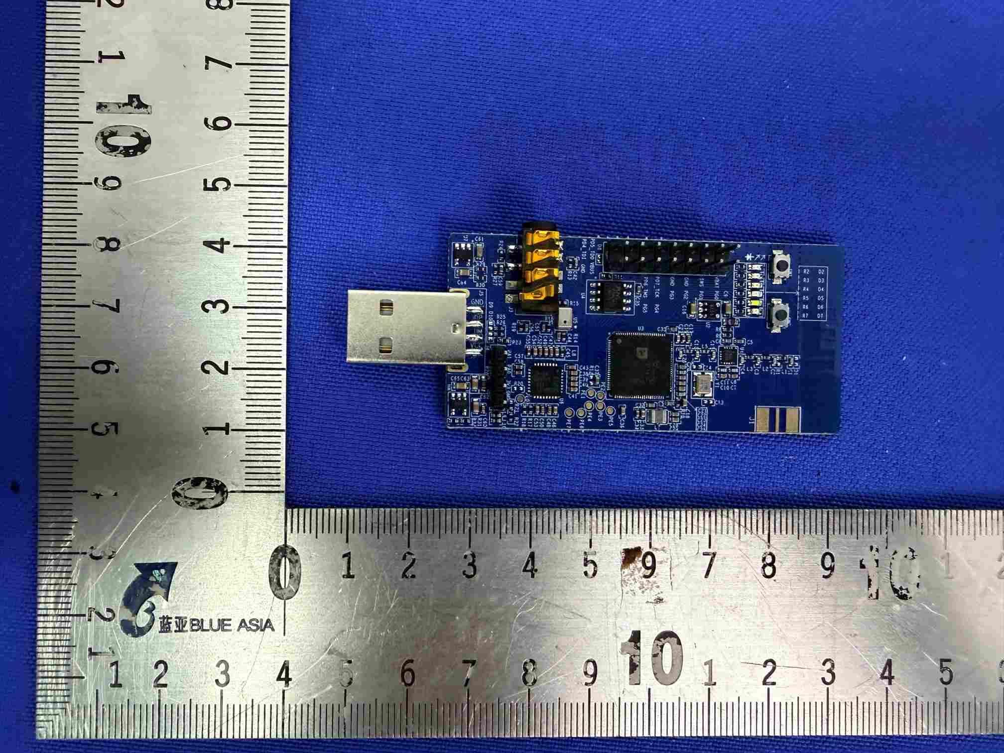
OEOTL3228XDG96D
Jul 14, 2026TL3228XDG96D
Equipment Class
DTS - Digital Transmission System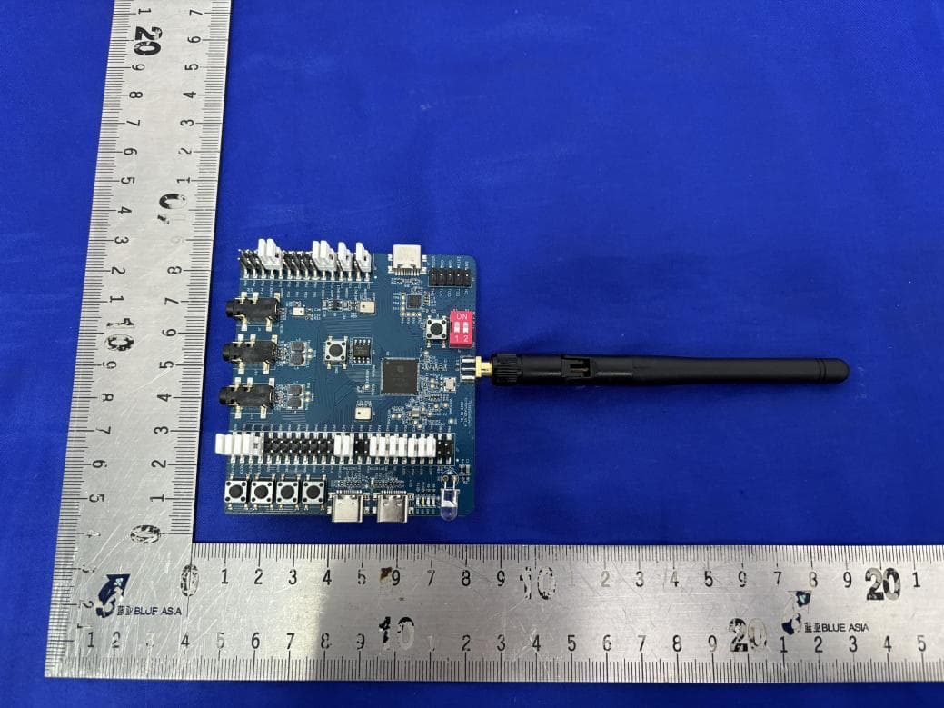
OEOTL3228XDK96D
Jun 01, 2026TL3228XDK96D
Equipment Class
DTS - Digital Transmission SystemOEOM3228AMRM0
Apr 14, 2026ML3228A-GAIA-M3-PE11
Equipment Class
DTS - Digital Transmission System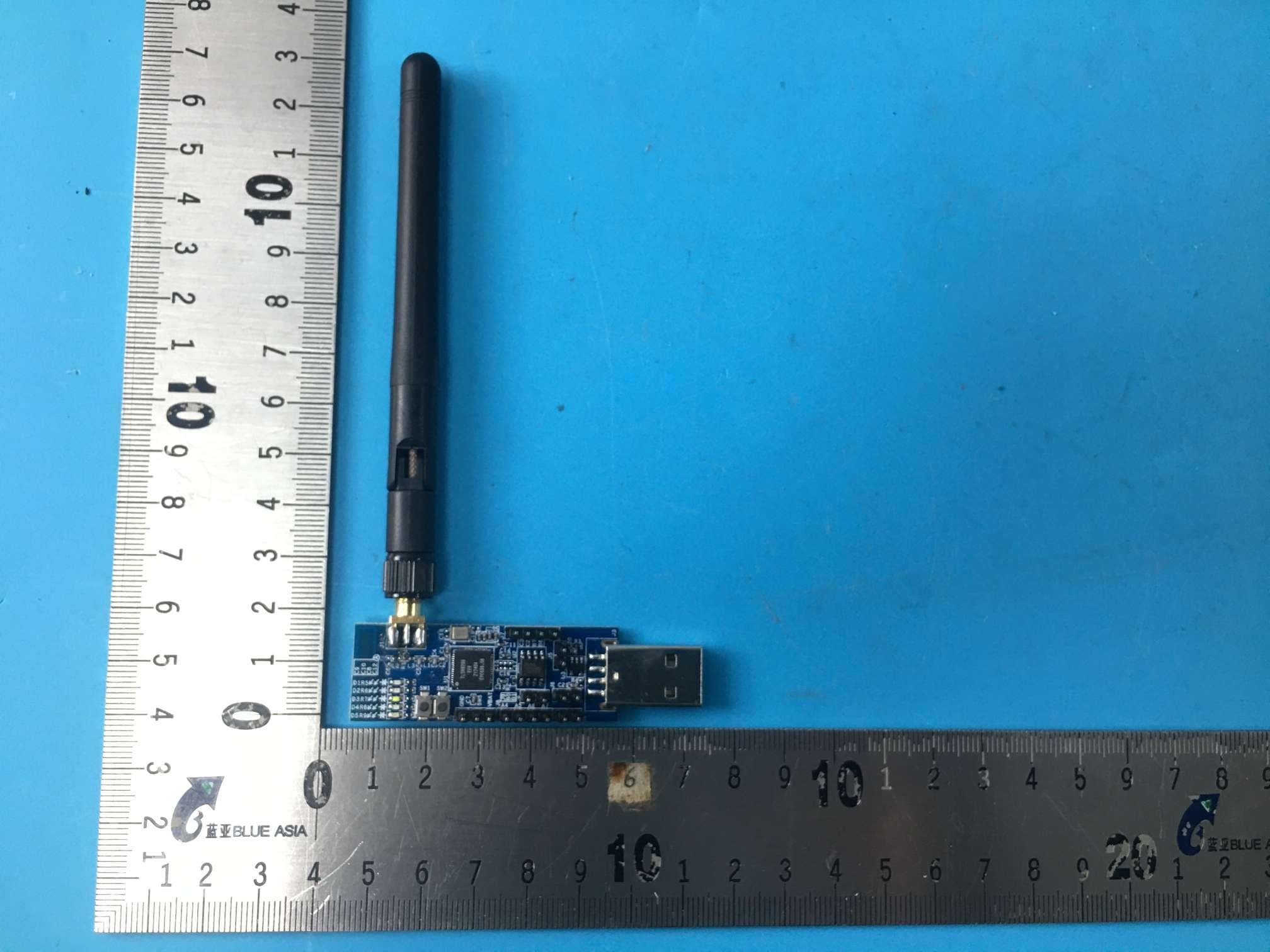
OEOTLSR8208EDG56D
Jun 16, 2024TLSR8208EDG56D
Equipment Class
DTS - Digital Transmission System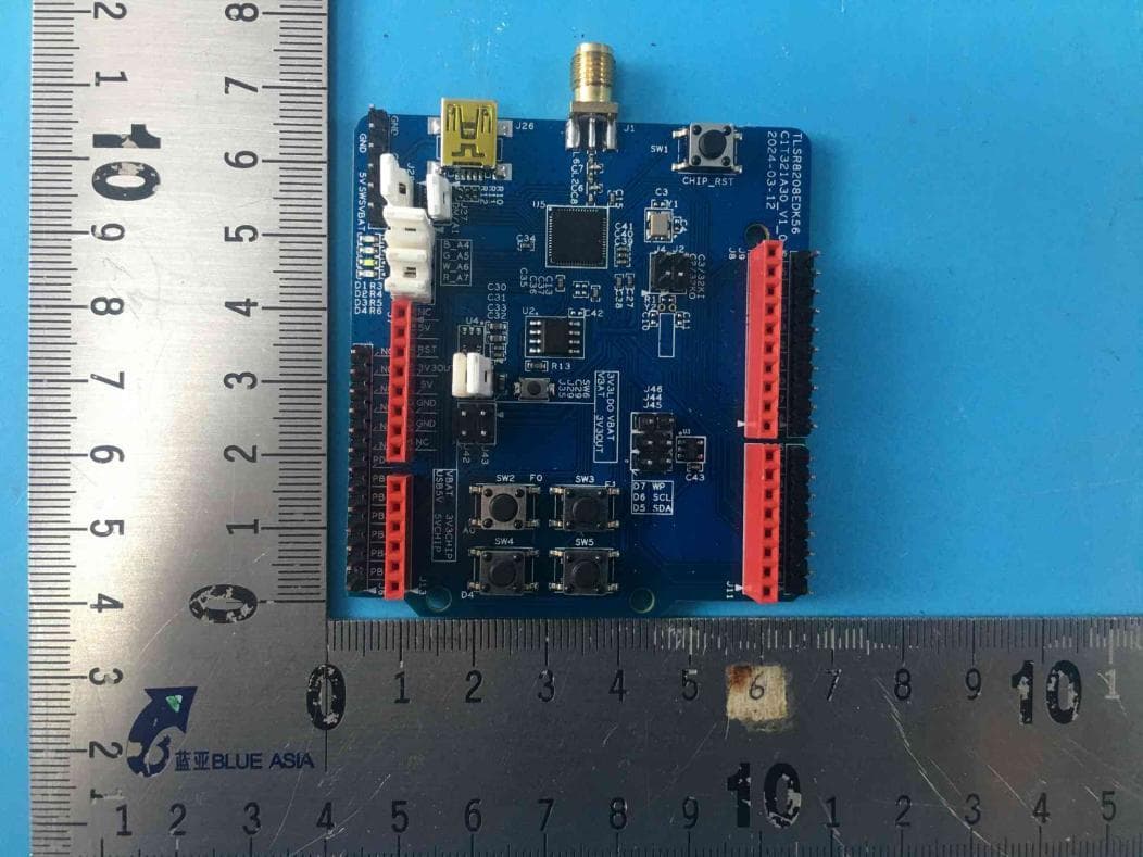
OEOTLSR8208EDK56D
Jun 16, 2024TLSR8208EDK56D
Equipment Class
DTS - Digital Transmission System