OFIOONTZTHE ULTRA PORTABLE WIRELESS BLUETOOTH SPEAKER
Soundworks, Inc.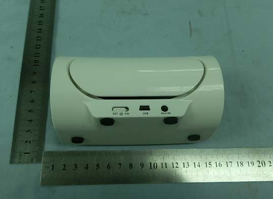
Click to zoom
Application Details
- Equipment Class
- DSS - Part 15 Spread Spectrum Transmitter
- Date of Grant
- Jul 10, 2012
- Application Purpose
- Original Equipment
- Date of Application
- Jul 10, 2012
- Equipment Note
- THE ULTRA PORTABLE WIRELESS BLUETOOTH SPEAKER
- Frequency Range
- 2402.00000000 - 2480.00000000
- Company
- Soundworks, Inc.
- Country
- United States
Documents & Files
Document Text
Text extracted from the exhibit documents filed with the FCC. Open a document above to read the original.
Users Manual
The OontZ Guide The Ultra Portable Wireless Bluetooth Speaker Oontz www.TheOontZ.com SoundWorks,INC. 1. Read these instructions – All the safety and operating instructions should be read before this product is operated. 2. Keep these instructions – The safety and operating instructions should be retained for future reference. 3. Heed all warnings – All warnings on the appliance and in the operating instructions should be adhered to. 4. Follow all instructions – All operating and use instructions should be followed. 5. Do not use this apparatus near water – The appliance should not be used near water or moisture – for example, in a wet basement or near a swimming pool, and the like. 6. Clean only with dry cloth. 7. Do not block any ventilation openings. Install in accordance with the manufacture’s instructions. 8. Do not install near any heat sources such as radiators, heat registers, stoves, or other apparatus (including amplifiers) that produce heat. 9. Do not defeat the safety purpose of the polarized or grounding plug. A polarized plug has two blades with one wider than the other. A grounding plug has two blades and a third grounding prong. The wide blade or the third prong is provided for your safety. If the provided plug does not fit into your outlet, consult an electrician for replacement of the obsolete outlet. 10. Protect the power cord from being walked on or pinched particularly at the plugs, convenience receptacles, and at the point where they exit from the apparatus. 11. Only use attachments/accessories specified by the manufacturer. 12. Use only with the cart, stand, tripod, bracket, or table specified by the manufacturer, or sold with the apparatus. When a cart or rack is used, use caution when moving the cart/apparatus combination to avoid injury from tip-over. Oontz www.TheOontZ.com SoundWorks,INC. Page1,Total11 © Copyright SoundWorks INC. Page2,Total11 © Copyright SoundWorks INC. Oontz www.TheOontZ.com SoundWorks,INC. 13. Unplug the apparatus during lightning storms or when unused for long periods of time. 14. Refer all servicing to qualified personnel. Servicing is required when the apparatus has been damaged in any way, such as power supply cord or plug is damaged, liquid has been spilled or objects have fallen into the apparatus has been exposed to rain or moisture, does not operate normally, or has been dropped. RISK OF ELECTRIC SHOCK DO NOT OPEN RISK OF ELECTRIC SHOCK DO NOT OPEN AVERTISSEMENT:RISQUE DC CHOC ELECTRIQUE-NE PAS OUVRIRAVERTISSEMENT:RISQUE DC CHOC ELECTRIQUE-NE PAS OUVRIR CAUTIONCAUTION - This lightning flash with arrowhead symbol within an equilateral triangle is intended to alert the user to the presence of non-insulated “dangerous voltage” within the product’s enclosure that may be of sufficient magnitude to constitute a risk of electric shock. - The exclamation point within an equilateral triangle is intended to alert the user to the presence of important operating and maintenance instructions in the literature accompanying the appliance. Thank you very much for selecting the OontZ. We hope that you will love it! The OontZ is designed to be simple to use, and this guide was written to help you get started quickly. Please take a few minutes to read through the guide, and try out the features on your OontZ. Contents The OontZ USB Cable Line in Cable OontZ Pouch The OontZ - Overview A B C H I F G E S O U R C E S O U R C E A-Power Switch B-USB Port C-Line in D-Standby Power/Source Button - - - - / Call/Play/Pause Button F-Volume Up Button G-Volume Down Button H-Previous Track Button I-Next Track Button - - - - Page3,Total11 © Copyright SoundWorks INC. E-Answer Call/Reject- / D AUX INAUX INOFFOFFONONUSBUSB Oontz www.TheOontZ.com SoundWorks,INC. The OontZ isCompatible with most Bluetooth devices that support A2DP Most Devices with A2DP Bluetooth can use the OontZ to play m usic and receive calls . The functionality and features that can be used on the OontZ are dependent on the bluetooth device (iPhone, iPod, Mobile Phone, MP3/MP4 Player, PC, Mac, etc.) the OontZ is to be paired with. Devices without A2DP cannot play music wirelessly through the OontZ. For further instructions on Bluetooth connectivity, please check the user guide for your A2DP Bluetooth device. Using the OontZ speaker with Non Bluetooth Devices Non-Bluetooth devices can be connected to the OontZ using the supplied Line-in cable (3.5mm Stereo) for speaker use only. Charging your OontZ Note: In order to recharge the OontZ, the Power Switch located on the back of the unit MUST be in the ON position. The OontZ has a built in rechargeable Lithium Ion battery To charge the OontZ, connect the USB cable to an available USB port on a PC or Mac or with a USB Power A dapter which has the official USB logo. Once the OontZ is fully charged, the LED will revert back to the previous LED status (i.e. if the OontZ was in a playing status during charging, the LED will illuminate BLUE). The OontZ CAN be used while it is recharging. Page4,Total11 © Copyright SoundWorks INC. Oontz www.TheOontZ.com SoundWorks,INC. Paring the OontZ with a Bluetooth Device 1. Ensure the OontZ is charged or that the OontZ is connected to a USB power source. 2. On the back of the OontZ, slide power button to ON. 3. Press and hold the source button, until the OontZ beeps and the red/blue LED starts flashing on the front of the OontZ. (The OontZ will remain in pairing mode for 3 minutes to connect to your Bluetooth device). 4.Use your Bluetooth device to search for OontZ and select it. 5.Enter pin "0000". 6.The OontZ will beep to confirm pairing, and the LED on front of the OontZ will stop flashing. This confirms successful pairing and you can play audio. 7.Check your Bluetooth device to ensure that connection is successful. 8. Now you can play your music wirelessly from your device to the OontZ. Note: If no connection is made after 3minutes, the OontZ will beep and the LED will turn OFF, repeat the steps above to re-enter pairing …
Text truncated - open the document above for the full version.
Block Diagram
5 5 4 4 3 3 2 2 1 1 DD CC BB AA Speaker DC IN U17 U18 STA339 Blue tooth FW09H01 AUX IN Switch System Block L/R Class D AMP L/R LDO DC-DC +5.0V +3.3V VDD Y1 24MHZ L/R KEY Amplifier
Cover Letter(s)
深圳市华标电子科技有限公司 Bontek Compliance Testing Laboratory Ltd DATE: June29, 2012 Dear TCB Section of Timco Engineering, Inc., Thank you for cooperation. I would like to submit FCC application of SoundWorks,Inc. . FCC ID: OFIOontz by your TCB Approval today. Best Regards, Bontek Compliance Testing Laboratory Ltd. Tony Wu/General Manager
Cover Letter(s)
SoundWorks, Inc FCC ID: OFIOontz POWER OF ATTORNEY June 29, 2012 Federal Communications Commission Authorization and Evaluation Division 7435 Oakland Mills Road Columbia, MD 21046 To Whom It May Concern: We, the undersigned, hereby authorize Bontek Compliance Testing Laboratory Ltd.(Tony Wu) on our behalf, to apply to the Federal Communications Commission on our equipment. Any and all acts carried out by Bontek Compliance Testing Laboratory Ltd. (Tony Wu) on our behalf shall have the same effect as acts of our own. This is to advise that we are in full compliance with the Anti-Drug Abuse Act.We, SoundWorks,Inc. are not subject to a denial of federal benefits pursuant to Section 5301 of the Anti-Drug Act of 1988, 21 USC853a, and no party to the application is subject to a denial of federal benefits pursuantto that section. Sincerely, SoundWorks,Inc. Loretta Skillings (Manager)
Cover Letter(s)
深圳市华标检测技术服务有限公司 Bontek Compliance Testing Laboratory Ltd
External Photos
External Photographs EUT – Combined View EUT – Top View EUT –Rear View EUT –Side View
ID Label/Location Info
FCC ID Label Sample for FCC ID: OFIOontz FCC ID: OFIOontz Model: Oontz
ID Label/Location Info
FCC ID Location FCC ID Location
Internal Photos
Internal Photographs EUT – Uncovered View EUT –PCB View EUT –PCB View EUT –PCB View EUT –PCB View EUT –PCB View EUT –BT Module View EUT –BT Module View EUT –Battery View EUT –Loudspeaker View EUT –Loudspeaker View
Operational Description
2.4GHz PCB antenna reference design Model: Version: V1.1 2012-2-18 FreeWings Technologies Co., Ltd. Tel: (86755)86116587 E-mail: [email protected] Add: 4F, Building2, Sangtai Industry Park, Xili, Nanshan, Shenzhen FreeWings, Free Communication FreeWings FreeCommunication www.free-wings.cn FreeWings Technologies Co., Ltd Page 2 of 6 2.4GHz PCB antenna reference design List of Contents 1 INTRODUCTION ....................................................................................................................................... 3 2 INVERTED-F ANTENNA .......................................................................................................................... 3 3 MEANDER LINE ANTENNA ................................................................................................................... 3 4 REAL DESIGNS.......................................................................................................................................... 4 5 RECOMMENDED RF PCB LAYOUT AND MOUNTING PATTERN ................................................ 5 RECORD OF CHANGES.................................................................................................................................... 6 IMPORTANT NOTICE....................................................................................................................................... 6 FreeWings FreeCommunication www.free-wings.cn FreeWings Technologies Co., Ltd Page 3 of 6 2.4GHz PCB antenna reference design 1 Introduction This document outlines two types of Printed Circuit Board (PCB) antenna used by FreeWings, which can be used with 2.4GHz radios such as Bluetooth WiFi. 2 type antennas will be discussed here: 1) Inverted-F 2) Meander Line 2 Inverted-F Antenna The inverted‐F is a quarterwave antenna. It is bent into an L‐shape. The shorter side is connected to earth. The longer side is left open‐circuit at the end. The feed point is located somewhere between the earth end and the open end. The resulting structure resembles the letter F and possesses the properties of both a loop antenna due to the circulating current from the feed point to ground and a whip antenna due to the open circuited straight section. In the PCB version, the antenna is printed on the top layer and a ground plane is placed near the antenna on the top layer. There must not be a ground plane underneath the antenna. The aim is to make the quarterwave section resonate at the midband frequency (which is 2441 MHz for 2.4GHz ISM radios). The feed point (which is the input/output connection) is connected to the L‐ shape at the point corresponding to 50Ω. Experiment with measurement to determine the correct location for the feed point and length of this antenna. 3 Meander Line Antenna QuarterWave Input Output FreeWings FreeCommunication www.free-wings.cn FreeWings Technologies Co., Ltd Page 4 of 6 2.4GHz PCB antenna reference design The length of the meander line antenna is difficult to predict. It is usually a bit longer than a quarterwave but dependent on its exact geometry and proximity to the ground plane. Note: In the figure the ground plane is shown in black. S is the distance from the ground plane. This type of antenna is always a PCB version. The antenna is printed on the top layer and a ground plane is placed near the antenna on the top layer. There must be no ground plane underneath the radiating section of the antenna. The real part of the impedance of this antenna is about 15Ω to 25Ω, depending on geometry and proximity to the ground plane. The impedance matching is done by adjusting the length of the antenna until the input impedance is at the unity conductance circle in Smith chart, in the top half of smith chart. A shunt capacitor is then connected between the antenna input and ground to match to 50Ω. Experimental measurement is used to determine the correct design. 4 Real Designs Type 1 Inverted‐F antenna Type 2 Meander line antenna FreeWings FreeCommunication www.free-wings.cn FreeWings Technologies Co., Ltd Page 5 of 6 2.4GHz PCB antenna reference design 5 Recommended RF PCB Layout and Mounting Pattern Placement and PCB layout are critical to optimize the performances of a module without on‐board antenna designs. The trace from the antenna port of the module to an external antenna should be 50Ω and must be as short as possible to avoid any interference into the transceiver of the module. The location of the external antenna and RF port of the module should be kept away from any noise sources and digital traces. A matching network might be needed in between the external antenna and RF port to better match the impedance to minimize the return loss. As indicated in Figure below, RF critical circuits of the module should be clearly separated from any digital circuits on the system board. All RF circuits in the module are close to the antenna port. The module, then, should be placed in this way that module digital part towards your digital section of the system PCB. General design recommendations are: z The length of the trace or connection line should be kept as short as possible. z 保持射频走线的长度尽可能短。 z Distance between connection and ground area on the top layer should at least be as large as the dielectric thickness. z 射频走线和地平面的间距要大于PCB介质的厚度。 z Routing the RF close to digital sections of the system board should be avoided. z 应避免有数字信号尤其是高速信号和时钟信号走到射频区域。 z To reduce signal reflections, sharp angles in the routing of the micro strip line should be avoided. Chamfers or fillets are preferred for rectangular routing; 45‐degree routing is preferred over Manhattan style 90‐degree routing. z 为了减小射频信号的反射,应避免走锐角的射频线,最好是用45度走线,或者用弧形走 线。 z Use as many vias as possible to connect the ground planes. z 在射频区域保证足够数量的接地过孔。 Red Antenna area, keep any ground or signal trace on all layer of PCB away. Yellow RF area; keep any signal trace on the component layer and below layer away. And place enough ground Vias on this area. Keep completed ground on…
Text truncated - open the document above for the full version.
Operational Description
FreeWings Confidential www.free-wings.cn Bluetooth Module Datasheet Model: FW3506 Version: V1.2 2010-08-14 FreeWings Technologies Co., Ltd. Tel: (86755)86116587 E-mail: [email protected] Add: 4F, Building2, Sangtai Industry Park, Xili, Nanshan, Shenzhen FreeWings, Free Communication FreeWings Confidential www.free-wings.cn FreeWings Technologies Co., Ltd Page 2 of 11 FW3506 Bluetooth Module Datasheet V1.2 List of Contents 1 INTRODUCTION ....................................................................................................................................... 3 2 KEY FEATURES ........................................................................................................................................ 3 3 APPLICATIONS ......................................................................................................................................... 3 4 BLOCK DIAGRAM .................................................................................................................................... 4 5 GENERAL SPECIFICATIONS................................................................................................................. 4 6 MODULE PACKAGE INFORMATION .................................................................................................. 5 6.1 P INOUT DIAGRAM.......................................................................................................................... 5 6.2 MODULE PIN DESCRIPTIONS........................................................................................................... 5 7 ELECTRICAL CHARACTERISTICS .....................................................................................................9 7.1 A BSOLUTE MAXIMUM RATINGS..................................................................................................... 9 7.2 RECOMMENDED OPERATING CONDITIONS..................................................................................... 9 8 PACKAGE DIMENSIONS......................................................................................................................... 9 9 RECOMMENDED REFLOW TEMPERATURE PROFILE ............................................................... 10 RECORD OF CHANGES.................................................................................................................................. 11 IMPORTANT NOTICE..................................................................................................................................... 11 FreeWings Confidential www.free-wings.cn FreeWings Technologies Co., Ltd Page 3 of 11 FW3506 Bluetooth Module Datasheet V1.2 1 Introduction FreeWings Technologies introduces the pioneer of the Bluetooth 2.1 class 2+EDR modules FW3506 which is a high performance, cost effective, low power and compact solution and also can be extended to Class 1 operation with external RF PA and LNA. The Bluetooth class 2 module provides a complete 2.4GHz Bluetooth system based on CSR Bluecore5-Multimedia External chipset which is a single chip radio and baseband IC for Bluetooth 2.4GHz systems. This module is fully compliant to Bluetooth v2.1 for data and audio communications. 2 Key Features • Fully Qualified Bluetooth v2.1 System. • Bluetooth Class2 operation (up to 10 meters range). • Bluetooth Class 1 operation with external RF PA and LNA. • Full-speed Bluetooth Operation with Full Piconet Support. • Scatternet Support. • Park, Sniff, Hold and Sleep ultra low power consumption modes. • Excellent compatibility with Cellular Telephones. • Minimum External Components Required. • Integrated 1.8V Linear Regulator • Electrical compliant to USB1.1 and 2.0 • SPI interface can upgrade firmware. • Slim module with 20mm x 13mm x 2.0mm • RoHS Compliant 3 Applications • Stereo Headphones • Automotive Hands-Free Kits • Echo Cancellation • High Performance Telephony Headsets • Enhanced Audio Applications • A/V Profile Support • Consumer electronic devices that require low power consumption. FreeWings Confidential www.free-wings.cn FreeWings Technologies Co., Ltd Page 4 of 11 FW3506 Bluetooth Module Datasheet V1.2 4 Block Diagram 5 General specifications Model Name FW3506 Product Description Bluetooth 2.1+EDR Class2 Module Bluetooth Standard Bluetooth v2.1 Standard Chipset CSR Bluecore5-Multimedia External Dimension 23mmx13mmx3.0mm Operating Conditions Voltage 3.3V Temperature -20~+70°C Storage Temperature -40~+85°C Electrical Specifications Frequency Range 2402~2480MHz Modulation FSK Maximum RF Transmit Power 4dBm RF power control range 24dB Receive Sensitivity -85dBm RF 2.4 GHZ Radio I/O RAM Baseband DSP MCU Kalimba DSP XTAL CSR Bluecore5‐Multimedia External 3.3V DC Input Balun Filter External memory FLASH SPI UART/USB PIO Audio In/Output PCM/I 2 S/SPDIF FreeWings Confidential www.free-wings.cn FreeWings Technologies Co., Ltd Page 5 of 11 FW3506 Bluetooth Module Datasheet V1.2 6 Module Package Information 6.1 Pinout Diagram Orientation from top of module Top View 6.2 Module Pin descriptions Pin No. Pin Name Pin Type Description 1 GND VSS Ground 2 PIO0/RXEN Bi-directional with programmable strength internal pull-up/down PIO line or Control output for external Tx/Rx switch(if fitted) 3 PIO1/TXEN Bi-directional with programmable strength internal pull-up/down PIO line or Control output for external PA(if fitted) 4 PIO3/USB_WAKE_UP Bi-directional with programmable strength internal pull-up/down PIO or output goes high to wake up PC when in USB mode 5 AIO0 Bi-directional Programmable input/output line 6 PIO2 Bi-directional with programmable strength internal pull-up/down PIO line 7 GND VSS Ground 8 PIO15 Bi-directional with programmable strength internal pull-up/down Programmable input/output line FreeWings Confidential www.free-wings.cn FreeWings Technologies Co., Ltd Page 6 of 11 FW3506 Bluetooth Module Datasheet V1.2 9 VREG_H Input Take high to enable high voltage linear regulator and switch mode regulator 10 PIO12 Bi-directiona…
Text truncated - open the document above for the full version.
Operational Description
Product Diagram Information 1ˊProduct function introduce BT196 is anAudio Systemwith built-in rechargeable lithium battery with a passive radiator to enhance the bass and with Bluetooth in. It has function of audio play through Bluetooth and Aux in audio player. 2ˊStructure 2.1 Structure Introduce The system is master consist of a piece of AMP˄GMP8603˅ˈTwo speakers, andBuilt-in 3.7V lithium battery for speaker system , Bluetooth module: FW09H01 the module crystal frequency is 24MHz. 2.2 Description Ensure the system is full charged, when we stir the speaker power switch “ON”, the system is powered on in stand by status, press power button at side, the system is in “ON” status and LED starts flashing in Red/Blue. Activate your Bluetooth device, then pair your Bluetooth device with the speakerˈafter connected successfully, we can control playing function of speaker by choose any key on the speaker, we can also connect with external Audio player by Aux in, and the buttons on speaker will be deactivated except power/source button. It used one -42dB D6MM/T2.2MM micphone for answer the elephone. 2.3 Power The speaker system is powered by rechargeable lithium battery with capacity of 1100mAh / 3.7V, or powered through connecting the USB charge cable to an available USB port (PC/Mac or with an optional dual USB power adapter) at 5V.
Schematics
FREEWINGS www.free-wings.cn 55 44 33 22 11 D D C C B B A A D15 D14 D13 D12 D11 D10 D9 D8 D7 D6 D5 D2 D1 D0 D4 D3 D15 D14 D13 D12 D11 D10 D9 D8 D7 D6 D5 D4 D3 D2 D1 D0 PIO10 PIO8 PIO7 PIO6 PIO5 PIO3 PIO0 PIO2 PIO1 SPK_RP SPK_RN MIC_LP PIO11 SPK_LP SPK_LN UART_TX SPI_CSB SPI_MOSI SPI_MISO UART_RX MIC_LN SPI_CLK USB_DP USB_DN MIC_BIAS GND RF RESETB A20A19 A20 A19 PIO4 PIO9 1V5_AUDIO MIC_RP MIC_RN PCM_IN PCM_SYNC PCM_CLK PCM_OUT AIO0 AIO1 UART_RTS UART_CTS PIO6UART_RTSVBATGND SPK_LPSPK_RPSPK_LNSPK_RNMIC_BIASPCM_CLKPCM_OUTPCM_INPCM_SYNCGND1V81V8_DCDCSPI_MOSISPI_MISOSPI_CSBLED1LED0SPI_CLK GND USB_DN USB_DP UART_CTS UART_TX UART_RX PIO9 PIO10 PIO11 PIO13 PIO8 PIO5 PIO13 PIO12 PIO15 PIO14 3V3PIO0PIO1PIO3AIO0PIO2GNDGNDPIO15VREG_ENPIO12PIO7PIO41V5AIO1PIO14VBUS LED0 LED1 MIC_LNMIC_LPMIC_RNMIC_RP VREG_EN VBUS 1V8_DCDC GND GND GND GND GND GND GND RF GND VBAT VBAT 3V3 VBUS RESETB 3V3 1V5 3V3 1V8 3V3 1V5 3V3 1V5 1V5 1V8 3V3 TitleSize Document Number Rev Date: Sheet of FW3506 <0.1> <FW3506-V02> A3 12 Monday, December 20, 2010 TitleSize Document Number Rev Date: Sheet of FW3506 <0.1> <FW3506-V02> A3 12 Monday, December 20, 2010 TitleSize Document Number Rev Date: Sheet of FW3506 <0.1> <FW3506-V02> A3 12 Monday, December 20, 2010 R16220KR16220K U5 fw3506 U5 fw3506 GND1 1 PIO0 2 PIO1 3 PIO3 4 AIO0 5 PIO2 6 GND2 7 PIO15 8 VREG_EN 9 PIO12 10 PIO7 11 PIO4 12 3V3 13 1V5 14 1V5_AUDIO 15 AIO1 16 PIO14 17 VBUS 18 PIO6 19 UART_RTS 20 VBAT 21 GND3 22 GND4 23 USB_DN 24 USB_DP 25 UART_CTS 26 UART_TX 27 UART_RX 28 PIO9 29 PIO10 30 PIO11 31 PIO13 32 PIO8 33 PIO5 34 GND5 35 PCM_SYNC 36 SPI_CLK 37 LED0 38 LED1 39 SPI_CSB 40 SPI_MISO 41 SPI_MOSI 42 1V8_DCDC 43 PCM_IN 45 1V8_LDO 44 PCM_OUT 46 PCM_CLK 47 MIC_BIAS 48 MIC_B_P 49 MIC_B_N 50 MIC_A_P 51 MIC_A_N 52 SPKR_B_N 53 SPKL_A_N 54 SPKR_B_P 55 SPKL_A_P 56 GND6 57 GND7 58 GND8 59 RF 60 GND9 61 GND10 62 GND11 63 GND12 64 GND13 65 R140R/niR140R/ni C14 10nF C14 10nF C13100nFC13100nF R7 1MR7 1M R12 0R/NIR12 0R/NI R52R2R52R2 C15 15pF C15 15pF C17 15pF C17 15pF R3 2R2R3 2R2 R8 2R2 R8 2R2 R9 2R2R9 2R2 C18100nFC18100nF C115pFC115pF C201uFC201uF U4 S29AL008J70BFI020 U4 S29AL008J70BFI020 A16 E6 A15 D6 A14 C6 A13 A6 A12 B6 A11 D5 A10 C5 A9 A5 A8 B5 A7 A2 A6 C2 A5 D2 A4 B1 A3 A1 A2 C1 A1 D1 A0 E1 DQ15/A-1 G6 DQ14 F5 DQ13 G5 DQ12 F4 DQ11 G3 DQ10 F3 DQ9 G2 DQ8 F2 DQ7 E5 DQ6 H5 DQ5 E4 DQ4 H4 DQ3 H3 DQ2 E3 DQ1 H2 DQ0 E2 NC0 C4 NC1 D4 NC2 B3 NC3 D3 #BYTE F6 #WE A4 #RESET B4 RY/#BY A3 #CE F1 #OE G1 VCC G4 VSS1 H6 VSS H1 A18 C3 A17 B2 C26.8pFC26.8pF R2 2R2R2 2R2 L3 22uH/ni L3 22uH/ni X1 7M26000314 X1 7M26000314 3 1 4 2 C11 1uFC11 1uF C9 10nF C9 10nF R4 2R2R4 2R2 L2 15nH L2 15nH C12 1uFC12 1uF G DS U6 2N7002K G DS U6 2N7002K 1 32 C224.7uF/niC224.7uF/ni R13 0R/NIR13 0R/NI U2 LFB212G45BAAD082 U2 LFB212G45BAAD082 UNBAL 1 DC 2 DC1 3 BAL 4 GND3 5 BAL1 6 GND1 7 GND2 8 RF POWER GPIO FLASH INTERFACE OSCILLATOR UART/USB/PCM/SPI GND LED CODEC NC U1 BC57E687C-GITB-E4 RF POWER GPIO FLASH INTERFACE OSCILLATOR UART/USB/PCM/SPI GND LED CODEC NC U1 BC57E687C-GITB-E4 VSS_RADIO J2 VSS_RADIO K2 VSS_AUDIO A1 VSS_AUDIO D3 VSS_DIG B4 VSS_LO L3 VSS_DIG C4 VSS_ANA P2 VSS_DIG C14 VSS_DIG H3 VSS_DIG L13 VSS_DIG N8 VSS_DIG N4 VSS_DIG N13 SUBS R3 TEST_EN G14 VREGIN_H A15 A16 P9 A18 N9 A17 R10 A15 R5 A14 P5 A13 N5 A12 R6 A11 P6 A10 N6 A9 R7 A8 P7 A5 R11 A4 P11 A3 N11 A2 R12 A1 P12 A0 C9 D15 A5 D14 C5 D13 B6 D12 A7 D11 C7 D10 C8 D9 B10 D8 A11 D7 B5 D6 A6 D5 C6 D2 A9 D1 C10 D0 B11 CS# A10 OE# C11 WE# N7 VSS_RADIO L2 VSS_LO K3 A7 P10 A6 N10 D4 B7 D3 B8 AU_REF_DCPL E3 MIC_BIAS B3 SPKR_B_N D2 SPKR_B_P D1 SPKR_A_P E1 MIC_B_N B1 MIC_A_N C1 MIC_A_P C2 PCM_CLK F13 PCM_IN G15 PCM_SYNC F14 PCM_OUT F15 SPI_MISO D15 SPI_MOSI E13 SPI_CS# E15 SPI_CLK E14 UART_CTS P15 UART_RTS R15 UART_TX N15 UART_RX N14 USB_DP P14 USB_DN P13 XTAL-OUT R2 XTAL-IN R1 PIO0 F1 PIO1 F2 PIO2 G3 PIO3 F3 PIO4 H13 PIO5 H14 PIO6 H15 PIO7 J13 PIO8 J14 PIO9 M14 PIO10 M13 PIO11 L14 VREGENABLE_L M2 VDD_USB R14 VDD_PIO G1 VDD_PADS L15 VREGENABLE_H B14 VDD_MEM A8 VDD_CORE K15 VDD_MEM A4 VDD_ANA P1 VDD_RADIO M1 VDD_CORE C15 AIO0 R4 RF_P K1 AUX_DAC H2 RF_N L1 AIO1 N3 NC1 G2 NC2 H1 NC3 J1 NC4 P4 PIO13 K14 PIO14 J15 PIO15 M15 A19 P8 A20 N12 FLASH_RP# R9 MIC_B_P B2 SPKR_A_N E2 VREGIN_L N2 VREGOUT_H B15 VREGIN_AUDIO A3 BAT_N B12 VSS C3 VSS J3 VSS M3 VSS F6 VSS G8 VSS H6 VSS J6 VSS K6 VDD_MEM B9 VDD_MEM R8 VDD-MEM R13 VDD_LO N1 VDD_AUDIO A2 VDD_CHG A12 VDD_SMPCORE A14 BAT_P B13 LX A13 LED1 D14 LED0 D13 RST# G13 LO_REF P3 VSS K7 VSS K8 VSS K9 VSS K10 VSS J7 VSS J8 VSS J9 VSS J10 VSS_DIG C13 VSS_DIG C12 VSS F7 VSS F8 VSS F9 VSS F10 VSS G6 VSS G7 VSS G9 VSS G10 VSS H7 VSS H8 VSS H9 VSS H10 PIO12 K13 C510nFC510nF C7 10nFC7 10nF C21 1uFC21 1uF C647nFC647nF
Schematics
D15 D14 D13 D12 D11 D10 D9 D8 D7 D6 D5 D2 D1 D0 D4 D3 D15 D14 D13 D12 D11 D10 D9 D8 D7 D6 D5 D4 D3 D2 D1 D0 PIO10 PIO8 PIO7 PIO6 PIO5 PIO3 PIO0 PIO2 PIO1 SPK_RP SPK_RN MIC_LP PIO11 SPK_LP SPK_LN UART_TX SPI_CSB SPI_MOSI SPI_MISO UART_RX MIC_LN SPI_CLK USB_DP USB_DN MIC_BIAS A20 A19 PIO4 PIO9 MIC_RP MIC_RN PCM_IN PCM_SYNC PCM_CLK PCM_OUT AIO0 AIO1 UART_RTS UART_CTS GND USB_DN USB_DP UART_CTS UART_TX UART_RX PIO9 PIO10 PIO11 PIO13 PIO8 PIO5 PIO13 PIO12 PIO15 PIO14 LED0 LED1 GND GND GND GND GND GND GND RF GND GND4 23 USB_DN 24 USB_DP 25 UART_CTS 26 UART_TX 27 UART_RX 28 PIO9 29 PIO10 30 PIO11 31 PIO13 32 PIO8 33 PIO5 34 GND6 57 GND7 58 GND8 59 RF 60 GND9 61 GND10 62 GND11 63 GND12 64 GND13 65 A16 E6 A15 D6 A14 C6 A13 A6 A12 B6 A11 D5 A10 C5 A9 A5 A8 B5 A7 A2 A6 C2 A5 D2 A4 B1 A3 A1 A2 C1 A1 D1 A0 E1 DQ15/A-1 G6 DQ14 F5 DQ13 G5 DQ12 F4 DQ11 G3 DQ10 F3 DQ9 G2 DQ8 F2 DQ7 E5 DQ6 H5 DQ5 E4 DQ4 H4 DQ3 H3 DQ2 E3 DQ1 H2 DQ0 E2 #BYTE F6 #WE A4 #RESET B4 RY/#BY A3 #CE F1 #OE G1 A18 C3 A17 B2 4 2 32 GND1 7 GND2 8 POWER GND POWER GND VSS_RADIO J2 VSS_RADIO K2 VSS_AUDIO A1 VSS_AUDIO D3 SUBS R3 A16 P9 A18 N9 A17 R10 A15 R5 A14 P5 A13 N5 A12 R6 A11 P6 A10 N6 A9 R7 A8 P7 A5 R11 A4 P11 A3 N11 A2 R12 A1 P12 A0 C9 D15 A5 D14 C5 D13 B6 D12 A7 D11 C7 D10 C8 D9 B10 D8 A11 D7 B5 D6 A6 D5 C6 D2 A9 D1 C10 D0 B11 CS# A10 OE# C11 WE# N7 VSS_RADIO L2 A7 P10 A6 N10 D4 B7 D3 B8 AU_REF_DCPL E3 MIC_BIAS B3 SPKR_B_N D2 SPKR_B_P D1 SPKR_A_P E1 MIC_B_N B1 MIC_A_N C1 MIC_A_P C2 PCM_CLK F13 PCM_IN G15 PCM_SYNC F14 PCM_OUT F15 SPI_MISO D15 SPI_MOSI E13 SPI_CS# E15 SPI_CLK E14 UART_CTS P15 UART_RTS R15 UART_TX N15 UART_RX N14 USB_DP P14 USB_DN P13 XTAL-OUT R2 XTAL-IN R1 PIO0 F1 PIO1 F2 PIO2 G3 PIO3 F3 PIO4 H13 PIO5 H14 PIO6 H15 PIO7 J13 PIO8 J14 PIO9 M14 PIO10 M13 PIO11 L14 AIO0 R4 RF_P K1 AUX_DAC H2 RF_N L1 AIO1 N3 NC1 G2 NC2 H1 NC3 J1 NC4 P4 PIO13 K14 PIO14 J15 PIO15 M15 A19 P8 A20 N12 FLASH_RP# R9 MIC_B_P B2 SPKR_A_N E2 BAT_N B12 LED1 D14 LED0 D13 LO_REF P3 PIO12 K13
Test Report
Test Report of FCC Part 15 C for FCC Certificate On Behalf of SoundWorks, Inc. FCC ID: OFIOontz Product Description: The Ultra Portable Wireless Bluetooth Speaker Model No.: Oontz Supplementary Model No.: N/A Prepared for: SoundWorks, Inc 2995 Woodside Road Suite 400 Woodside Ca. 94062 Prepared by: Bontek Compliance Testing Laboratory Ltd 1/F, Block East H-3, OCT Eastern Ind. Zone, Qiaocheng East Road, Nanshan, Shenzhen, China Tel: 86-755-86337020 Fax: 86-755-86337028 Report No.: BCT12FR-0893E Issue Date: June 29, 2012 Test Date: June 26 ~29, 2012 Test by: Reviewed By: Nie Quan Kevin Chi Report No.: BCT12FR-0893E Page 2 of 43 FCC ID: OFIOontz TABLE OF CONTENTS 1. GENERAL INFORMATION....................................................................................................................................4 1.1 PRODUCT DESCRIPTION FOR EQUIPMENT UNDER TEST (EUT).........................................................................4 1.2 RELATED SUBMITTAL(S) / GRANT (S)...................................................................................................................4 1.3 TEST METHODOLOGY...........................................................................................................................................4 1.4 TEST FACILITY......................................................................................................................................................5 2. SYSTEM TEST CONFIGURATION......................................................................................................................6 2.1 EUT CONFIGURATION..........................................................................................................................................6 2.2 EUT EXERCISE.....................................................................................................................................................6 2.3 GENERAL TEST PROCEDURES.............................................................................................................................6 2.4 LIST OF MEASURING EQUIPMENTS USED........................................................................................…
Text truncated - open the document above for the full version.
Contact Information
Applicant
Mike Roets
Test Firm
Bontek Compliance Testing Laboratory LtdTony Wu
Technical Specifications
| # | Rule Parts | Frequency Range | Power Output |
|---|---|---|---|
| 1 | 15C | 2.40 GHz - 2.48 GHz | 459.00 µW |
Other Applications from Soundworks, Inc.

OFIOONTZXL
Jun 18, 2013OONTZ XL
Equipment Class
DSS - Part 15 Spread Spectrum Transmitter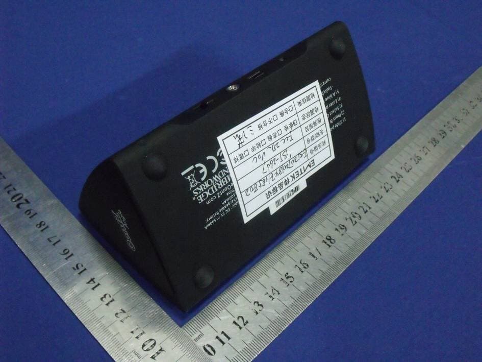
OFIOONTZANGLE
Aug 06, 2012The Ultra Portable Wireless Bluetooth Speaker
Equipment Class
DSS - Part 15 Spread Spectrum Transmitter