OJM-OTX-XXX-LRHSALong-Range Handheld Transmitter
Linx Technologies
Click to zoom
Application Details
- Equipment Class
- DSC - Part 15 Security/Remote Control Transmitter
- Date of Grant
- Apr 11, 2007
- Application Purpose
- Original Equipment
- Date of Application
- Apr 11, 2007
- Equipment Note
- Long-Range Handheld Transmitter
- Frequency Range
- 433.92000000 - 433.92000000
- Company
- Linx Technologies
- Country
- United States
Documents & Files
Document Text
Text extracted from the exhibit documents filed with the FCC. Open a document above to read the original.
Users Manual
DESCRIPTIONThe Linx OTX-***-HH-LR8-HS Long-RangeHandheld Transmitter is ideal for general-purpose remote control and commandapplications which require high security andlong transmission distances. This unit has beenpre-certified for FCC Part 15, Industry Canada,and European CE (433MHz only) compliance,reducing costs and time to market. Available in315, 418 (standard), or 433.92MHz, this smallremote has a transmission range of up to 1,000feet when combined with an LR Series receiver.The transmitter unit can be configured with 1 to8 buttons and the keypad and labeling can bemodified to meet specific OEM customerrequirements. Security is dramaticallyenhanced by the on-board HS Series encoder,which uses Cipherlinx™ technology, a high-security encryption algorithm and wirelessprotocol. When paired with an HS Seriesdecoder, transmitter identity can be determinedand button permissions established. The unituses a single 3V CR2032 lithium button cell.FEATURES FCC, Canada, and CE pre-certified Highly secure, encrypted transmission 1 to 8 buttons Customizable keypad APPLICATIONS INCLUDE Secure Remote Control Keyless Entry Garage / Gate Openers Lighting Control Call Systems Home / Industrial Automation Wire Elimination OEM ConfigurationsWith a one-time NRE andminimum order, Linx can configurethe keypad and label areas tomeet your specific requirements.Contact Linx for details. HS LONG-RANGE HANDHELD TRANSMITTER DATA GUIDE 0.60" 0.20" 1.375"2.81" 1.62" 2.00" 1.35" R 0.2" Revised 3/30/07 Figure 1: Package Dimensions WIRELESS MADE SIMPLE ® 2 1 3 4 A B C D ON ONONON FASCO Lights Spa O N O N O N O FF O FF O FF Pool PART # DESCRIPTIONOTX-***-HH-LR8-HS-xxx HS Long-Range TransmitterMDEV-***-HH-LR8-HS HH -LR8 Master Development System *** = 315, 418 (Standard), 433.92MHzxxx = Reserved for custom colors. Leave blank for standard black ORDERING INFORMATION CipherLinx Technology TM Page 3 Page 2 THEORY OF OPERATION The OTX-***-HH-LR8-HS Long-Range Handheld Transmitter combines an LRSeries transmitter and an antenna with an on-board HS Series encoder to forma highly reliable and secure RF remote-control transmitter. The LR Seriestransmitter is a low-cost, high-performance synthesized OOK transmitter. It’s synthesized architecture delivers outstanding stability and frequency accuracy,while minimizing the effects of antenna port loading and mismatching. This reduces or eliminates frequency pulling, bit contraction, and other negativeeffects that are common to SAW-based transmitter architectures, providing asignificantly higher level of performance and reliability.When a button is pressed on the transmitter, power is applied to the internalcircuitry and the encoder is enabled. The encoder then detects the logic statesof the button data lines. These states are formatted into an encrypted messagethat is output to the transmitter module. This cycle continues until the button isreleased. The encoder data is used to modulate the transmitter, which conveysthe data into free space through the antenna. Once data is received, a decoderIC is used to decrypt the transmitter’s commands. If decryption is successful, thedecoder’s outputs are set to replicate the transmitter’s button states. Theseoutputs can then be used to activate whatever external circuitry is required by theapplication.The transmitter is compatible with several Linx receiver products. Forapplications where range is critical, the LR Series receiver is the best choice dueto its outstanding sensitivity. When the transmitter is combined with an LR Seriesreceiver and an HS Series decoder, ranges of up to 1,000 feet are possible.Applications operating over shorter distances will also benefit from the increasedlink reliability and superior noise immunity provided by the LR Series receiver. 1. Characterized, but not testedNotes ELECTRICAL SPECIFICATIONS Parameter Designation Min. Typical Max. Units Notes POWER SUPPLYOperating Voltage V CC 2.1 3.0 3.6 VDC – Supply Current I CC – 3.4 – mA – Power-Down Current I PDN – 5.0 – nA 1 TRANSMITTER SECTIONTransmit Frequency Range: F C OTX-315-HH-LR8-HS – 315 – MHz – OTX-418-HH-LR8-HS – 418 – MHz – OTX-433-HH-LR8-HS – 433.92 – MHz – Center Frequency Accuracy – -50 – +50 kHz – ENVIRONMENTALOperating Temperature Range – -40 – +85 °C 1 SECURITY OVERVIEW The HS Long-Range Handheld transmitter uses the HS Series encoder, which isbased on Cipherlinx™ technology. CipherLinx™ is a high-security encryptionalgorithm and wireless protocol designed for remote control and remote keylessentry applications. It provides a much greater level of security and many morefeatures than older technologies on the market, such as fixed address or “rollingcode” systems. Additionally, the CipherLinx™ protocol is much more advancedthan the simple PWM method employed by many systems. By utilizing anadvanced serial protocol, CipherLinx™ is able to offer superior noise immunity,greater range, and greater link reliability, all of which are key factors in a wirelesssystem. CipherLinx™ never sends or accepts the same data twice, never loses sync, andchanges codes with every packet, not just every button press. The encryptionthat is used in CipherLinx™ is based on the Skipjack cipher developed by theU.S. National Security Agency (NSA), and is widely considered one of the mostsecure ciphers available. The CipherLinx™ algorithm has been evaluated byIndependent Security Evaluators (ISE), a company that has testified beforeCongress as experts on electronic security. They concluded that “In short, theCipherLinx™ protocol in the HS Series is well-designed and is an excellentchoice for applications requiring a secure unidirectional link.” In addition to this high level of security, CipherLinx™ also offers a number offeatures that are unique among remote control products. These include a largenumber of data lines, internal key generation, “button level” control permissions,an optional encoder PIN, as well as the ability for the decoder to identify theo…
Text truncated - open the document above for the full version.
Attestation Statements
159 ORT LANE MERLIN, OREGON 97532 PHONE: (800) 736-6677 FAX: (541) 471-6251 www.linxtechnologies.com 4/10/2007 CETCB 114 Olinda Drive Brea, CA 92823 Gentlemen, This is a letter of authorization to accept Compatible Electronics, Inc. as an Agent for Linx Technologies, 159 Ort Lane, Merlin Oregon 97532, for a period of one year, to sign applications before the certification body on our behalf, to make representations to you on our behalf, and to receive and exchange data between our company and the certification body in connection with certification of the following Linx Technologies products: HS Long-Range Hand Held Transmitter HS Compact Hand Held Transmitter under FCC Docket Number 20780 and General Docket Number 80-284 pursuant to Part 15 of the FCC Rules and Regulations. Please also accept this letter as an attestation that neither Linx Technologies nor any of its officers, directors, or persons holding 5% or more of the outstanding stock or shares, voting or non-voting, have been denied federal benefits under section 5301 of the Anti-Drug-Abuse act of 1988, 21 U.S.C. 853(a). In addition, Linx Technologies will notify the Federal Communications Commission if, at any time, the situation changes causing Linx Technologies to be denied federal benefits. If you have any further questions or need additional information, please feel free to give me a call at 541-471-6256. Sincerely, Justin Hopper Engineering Manager
Attestation Statements
159 ORT LANE MERLIN, OREGON 97532 PHONE: (800) 736-6677 FAX: (541) 471-6251 www.linxtechnologies.com April 11, 2007 CETCB 114 Olinda Drive Brea, CA 92823 RE: Modification letter for the HS Long-Range Handheld Transmitter Dear Review Personnel: In production the value R13 will be set to maintain consistent compliance with FCC limits and the levels present during testing. The testing laboratory at our instruction has populated R13 with the following: For the 315 MHz Version – 2200 ohms For the 418 MHz Version – 1500 ohms For the 433.92 MHz Version – 1200 ohms Sincerely, Justin Hopper Engineering Manager
Cover Letter(s)
159 ORT LANE MERLIN, OREGON 97532 PHONE: (800) 736-6677 FAX: (541) 471-6251 www.linxtechnologies.com April 10, 2007 CETCB 114 Olinda Drive Brea, CA 92823 Subject: Request for withholding from public disclosure the schematics, block diagrams, and operational description pursuant to an application for certification Gentlemen: We, Linx Technologies, would like to request that all schematics, block diagrams, and operational descriptions submitted with the application for certification be withheld from public disclosure as per Section 0.459 of FCC Rules. This request is made under the provisions of Section 0.457 (d) of the Commission’s Rules, and Section 552 (b)(4) of the Freedom of Information Act. These sections authorize the withholding from public inspection, those materials which would be privileged as a matter of law if retained by the person submitting them, and materials which would not customarily be released to the public by that person. If you have any questions, please do not hesitate to contact us at 541-471-6256. Sincerely, Justin Hopper Engineering Manager
Cover Letter(s)
Mike From: Kyle Fujimoto [[email protected]] Sent: Wednesday, December 27, 2006 7:39 AM To: [email protected] Subject: Fwd: Response to Inquiry to FCC (Tracking Number 379492) 4/10/2007 Mike, Below is the response from the FCC regarding the Linx project. Regards, Kyle Fujimoto Test Engineer -- Compatible Electronics, Inc. -- Brea Division Phone:(714) 579-0500 Fax: (714) 579-1850 [email protected] http://www.celectronics.com -----Original Message----- From: Generic Office of Engineering Technology <[email protected]> To: [email protected] Date: Tue, 26 Dec 2006 10:00:24 -0500 (EST) Subject: Response to Inquiry to FCC (Tracking Number 379492) Inquiry: Hello, I have a question regarding the duty cycle plots and calculation for a pulsed modulation transmitter that is going to be certified. The device that is going to be certified will be using an encoder that uses an algorithm to change the code of each packet during transmission, not just after each button press. This is done for security purposes to prevent code capture, similar to other code hopping encoders already on the market. Because of this, it makes it essentially impossible to acquire the code and provide the duty cycle plots that are typically required for certification of a device like this since the code changes with every transmitted packet. The manufacturer of the encoder states that the duty cycle may change slightly, but will never be higher than a certain percentage. In such a case, would it be permitted for the Grantee to provide a written explanation, from the manufacturer of the encoder, of what the highest possible duty cycle is instead of showing the plots and then use this explanation when we calculate the average field strength and submit for certification? Thank you for your help. Response: You should obtain an explanation and measurement data from the manufacturer showing the highest possible duty cycle and submit with your application for Certification. Do not reply to this message. Please select the Reply to an Inquiry Response link from the OET Inquiry System to add any additional information pertaining to this inquiry. 4/10/2007
Cover Letter(s)
Scott McCutchan From: Scott McCutchan [[email protected]] Sent: Wednesday, April 11, 2007 1:09 PM To: '[email protected]' Cc: '[email protected]' Subject: FCC ID: OJM-OTX-XXX-LRHSA 4/11/2007 Mr. Fujimoto: In order for processing of this certification application (FCC ID: OJM-OTX-XXX-LRHSA) to continue, the following issue(s) will have to be addressed: 1) Please provide a signed modification letter from the applicant, stating that the modifications will be implemented on all production units. 2) The schematics need to change, to match the modifications that were made. The item(s) indicated above must be submitted before processing can continue on the above referenced application. Failure to provide the requested information within 60 days of the original e-mail date may result in application dismissal and forfeiture of the filing fee. Also, please note that partial responses increase processing time and should not be submitted. Please upload responses and/or exhibits to the electronic filing website. Your correspondence number is OJM-OTX-XXX-LRHSA-1. Best regards, Scott McCutchan Operations Manager Compatible Electronics TCB
ID Label/Location Info
159 ORT LANE ● MERLIN, OR 97532 PHONE: (800) 736-6677 ● FAX: (541) 471-6251 The FCC and Industry Canada ID numbers for the Long Range Handheld transmitter are: FCC ID: OJM-OTX-XXX-LRHSA IC: 5840A-LRHSXXXA The label and the location on the unit are shown below. The required disclaimers will be included in the User’s Manual. The label is applied to the back of the unit. This is shown below in actual size.
Test Report
Report Number: B70103B1 FCC Part 15 Subpart B and FCC Section 15.231 Test Report Long-Range Handheld Transmitter P/N: OTX-xxx-HH-LR8-HS Brea Division 114 Olinda Drive Brea, CA 92823 (714) 579-0500 Agoura Division 2337 Troutdale Drive Agoura, CA 91301 (818) 597-0600 Silverado Division 19121 El Toro Road Silverado, CA 92676 (949) 589-0700 Lake Forest Division 20621 Pascal Way Lake Forest, CA 92630 (949) 587-0400 Page 1 of 16 FCC PART 15, SUBPART B and C TEST REPORT for LONG-RANGE HANDHELD TRANSMITTER P/N: OTX-xxx-HH-LR8-HS Prepared for LINX TECHNOLOGIES 159 ORT LANE MERLIN, OREGON 97532 Prepared by:_____________________ KYLE FUJIMOTO Approved by:____________________ JAMES ROSS COMPATIBLE ELECTRONICS INC. 114 OLINDA DRIVE BREA, CALIFORNIA 92823 (714) 579-0500 DATE: FEBRUARY 16, 2007 REPORT APPENDICES TOTAL BODY A B C D E PAGES 16 2 2 2 12 27 61 This report shall not be reproduced except in full, without the written approval of Compatible Electronics. Report Number: B70103B1 FCC Part 15 Subpart B and FCC Section 15.231 Test Report Long-Range Handheld Transmitter P/N: OTX-xxx-HH-LR8-HS Brea Division 114 Olinda Drive Brea, CA 92823 (714) 579-0500 Agoura Division 2337 Troutdale Drive Agoura, CA 91301 (818) 597-0600 Silverado Division 19121 El Toro Road Silverado, CA 92676 (949) 589-0700 Lake Forest Division 20621 Pascal Way Lake Forest, CA 92630 (949) 587-0400 Page 2 of 16 TABLE OF CONTENTS Section / Title PAGE GENERAL REPORT SUMMARY 4 SUMMARY OF TEST RESULTS 4 1. PURPOSE 5 2. ADMINISTRATIVE DATA 6 2.1 Location of Testing 6 2.2 Traceability Statement 6 2.3 Cognizant Personnel 6 2.4 Date Test Sample was Received 6 2.5 Disposition of the Test Sample 6 2.6 Abbreviations and Acronyms 6 3. APPLICABLE DOCUMENTS 7 4. DESCRIPTION OF TEST CONFIGURATION 8 4.1 Description Of Test Configuration - EMI 8 4.1.1 Cable Construction and Termination 9 5. LISTS OF EUT, ACCESSORIES AND TEST EQUIPMENT 10 5.1 EUT and Accessory List 10 5.2 EMI Test Equipment 11 6. TEST SITE DESCRIPTION 12 6.1 Test Facility Description 12 6.2 EUT Mounting, Bonding and Grounding 12 7. TEST PROCEDURES 13 7.1 Radiated Emissions (Spurious and Harmonics) Test 13 7.2 Radiated Emissions (Spurious and Harmonics) Test (continued) 14 7.3 Bandwidth of the Fundamental 15 8. CONCLUSIONS 16 Report Number: B70103B1 FCC Part 15 Subpart B and FCC Section 15.231 Test Report Long-Range Handheld Transmitter P/N: OTX-xxx-HH-LR8-HS Brea Division 114 Olinda Drive Brea, CA 92823 (714) 579-0500 Agoura Division 2337 Troutdale Drive Agoura, CA 91301 (818) 597-0600 Silverado Division 19121 El Toro Road Silverado, CA 92676 (949) 589-0700 Lake Forest Division 20621 Pascal Way Lake Forest, CA 92630 (949) 587-0400 Page 3 of 16 LIST OF APPENDICES APPENDIX TITLE A Laboratory Recognitions B Modifications to the EUT C Additional Models Covered Under This Report D Diagrams, Charts, and Photos • Test Setup Diagrams • Radiated Emissions Photos • Antenna and Effective Gain Factors E Data Sheets LIST OF FIGURES FIGURE TITLE 1 Plot Map And Layout of 3 Meter Radiated Site Report Number: B70103B1 FCC Part 15 Subpart B and FCC Section 15.231 Test Report Long-Range Handheld Transmitter P/N: OTX-xxx-HH-LR8-HS Brea Division 114 Olinda Drive Brea, CA 92823 (714) 579-0500 Agoura Division 2337 Troutdale Drive Agoura, CA 91301 (818) 597-0600 Silverado Division 19121 El Toro Road Silverado, CA 92676 (949) 589-0700 Lake Forest Division 20621 Pascal Way Lake Forest, CA 92630 (949) 587-0400 Page 4 of 16 GENERAL REPORT SUMMARY This electromagnetic emission test report is generated by Compatible Electronics Inc., which is an independent testing and consulting firm. The test report is based on testing performed by Compatible Electronics personnel according to the measurement procedures described in the test specifications given below and in the "Test Procedures" section of this report. The measurement data and conclusions appearing herein relate only to the sample tested and this report may not be reproduced without the written permission of Compatible Electronics, unless done so in full. This report must not be used to claim product endorsement by NVLAP, NIST or any other agency of the U.S. Government. Device Tested: Long-Range Handheld Transmitter P/N: OTX-xxx-HH-LR8-HS S/N: N/A Product Description: See Expository Statement. Modifications: The EUT was modified in order to meet the specifications. Please see the list located in Appendix B. Manufacturer: Linx Technologies 159 Ort Lane Merlin, Oregon 97532 Test Dates: December 28, 2006 and January 2, 2007 Test Specifications : EMI requirements CFR Title 47, Part 15 Subpart B; and Subpart C, Sections 15.205, 15.209 and 15.231 Test Procedure: ANSI C63.4 Test Deviations: The test procedure was not deviated from during the testing. SUMMARY OF TEST RESULTS TEST DESCRIPTION RESULTS 1 Conducted RF Emissions, 150 kHz – 30 MHz This test was not performed because the EUT is battery powered only and does not connect to the AC public mains. 2 Radiated RF Emissions, 9 kHz – 4400 MHz Complies with the Class B limits of CFR Title 47, Part 15, Subpart B; and Subpart C, sections 15.205, 15.209, and 15.231. Report Number: B70103B1 FCC Part 15 Subpart B and FCC Section 15.231 Test Report Long-Range Handheld Transmitter P/N: OTX-xxx-HH-LR8-HS Brea Division 114 Olinda Drive Brea, CA 92823 (714) 579-0500 Agoura Division 2337 Troutdale Drive Agoura, CA 91301 (818) 597-0600 Silverado Division 19121 El Toro Road Silverado, CA 92676 (949) 589-0700 Lake Forest Division 20621 Pascal Way Lake Forest, CA 92630 (949) 587-0400 Page 5 of 16 1. PURPOSE This document is a qualification test report based on the Electromagnetic Interference (EMI) tests performed on the Long-Range Handheld Transmitter, P/N: OTX-xxx-HH-LR8-HS. The EMI measurements were performed according to the measurement procedure described in ANSI C63.4. The tests were performed in order to determine whether the electromagnetic emissions from the equipment under test, referred to as EUT hereafter, are within the…
Text truncated - open the document above for the full version.
Test Report
HS-Encoder worst-case duty cycle plots for FCC By: Chris Murphy 1/5/2007 Definitions: 1. All data is sent LSB first (D0-D7) 2. Start bit = 0 3. Stop bit = 1 4. Preamble Byte = start bit + 1100 1111 + stop bit a. Error check bits 0-2 never change (110) b. Inversion bit 3 is clear (0) since 50% is a non-inverting packet c. UserID bits 4-7 set at 15 for worst case scenario (1111) 5. Each byte of data portion = start bit + 0101 0101 + stop bit *Note: start bit appears merged with bit-0 and stop bit appears merged with bit-7 6. Start sequence = wake bits + noise filter + preamble 7. Packet = processing period + start sequence + data 8. Message = Packet-A + Packet-B 9. Pulse Train = 1 complete message Baud rate = 4800bps *Complete 200ms data capture from HS encoder at 4800bps *Complete 100ms data capture from HS encoder at 4800bps * Total time of 1 pulse train = 57.0006ms * Zoomed in on processing period and start sequence of packet-A * Zoomed in on data portion of packet A * Zoomed in on processing period and start sequence of packet-B * Zoomed in on data portion of packet-B * Pulse measurement #1 = 3.3982ms (processing pulse, only 1of these per pulse train) * Pulse measurement #2 = 200.465us (wake pulses, 4 of these per pulse train) * Pulse measurement #3 = 1.4114ms (noise filter, 2 of these per pulse train) * Pulse measurement #4 = 404.101us (error check, 2 of these per pulse train) * Pulse measurement #5 = 1.0659ms (UserID + stop bit, 2 of these per pulse train) * Pulse measurement #6 = 215.009us (bits 1,3,5 of each byte of data, 48 of these per pulse train) * Pulse measurement #7 = 464.271us (bit 7 + stop bit of each byte of data, 16 of these per pulse train) Pulse Description Pulse Meas. #Pulse Length (us)Pulses per Train Total Time (us) Processing time 1 3398.2 1 3398.2 Wake bits 2 200.465 4 801.86 Noise filter 3 1411.4 2 2822.8 Error check 4 404.101 2 808.202 UserID + stop bit 5 1065.9 2 2131.8 Bits 1,3,& 5 of ea. data byte 6 215.009 48 10320.432 Bit 7 + stop bit of ea. data byte 7 464.271 16 7428.336 Total On-Time @ 4800bps 27711.63 Total On-Time = 27711.63us Total Time = 57000.6us 27711.63 /57000.6 = 0.48616 Duty Cycle @ 4800bps = 48.6% Baud rate = 28800bps * Complete 100ms data capture from HS encoder at 28800bps * Total time of 1 pulse train = 25.5264ms * Zoomed in on processing period of packet-A * Zoomed in on start sequence of packet-A * Zoomed in on data portion of packet A * Zoomed in on processing period of packet-B * Zoomed in on start sequence of packet-B * Zoomed in on data portion of packet B * Pulse measurement #1 = 3.38245ms (processing pulse, only 1of these per pulse train) * Pulse measurement #2 = 32.909us (wake pulses, 4 of these per pulse train) * Pulse measurement #3 = 1.40564ms (noise filter, 2 of these per pulse train) * Pulse measurement #4 = 65.091us (error check, 2 of these per pulse train) * Pulse measurement #5 = 223.27us (UserID + stop bit, 2 of these per pulse train) * Pulse measurement #6 = 42.727us (bits 1,3,5 of each byte of data, 48 of these per pulse train) * Pulse measurement #7 = 126.000us (bit 7 + stop bit of each byte of data, 16 of these per pulse train) Pulse Description Pulse Meas. #Pulse Length (us)Pulses per Train Total Time (us) Processing time 1 3382.45 1 3382.45 Wake bits 2 32.909 4 131.636 Noise filter 3 1405.64 2 2811.28 Error check 4 65.091 2 130.182 UserID + stop bit 5 223.27 2 446.54 Bits 1,3,& 5 of ea. data byte 6 42.727 48 2050.896 Bit 7 + stop bit of ea. data byte 7 126 16 2016 Total On-Time @ 28800bps 10968.984 Total On-Time = 10968.984us Total Time = 25526.4us 10968.984 / 25526.4 = 0.42971 Duty Cycle @ 28800bps = 43.0%
Test Report
HS Series Encoder Data Structure Power Up Is the SEND Line High? Send Message YES NO The HS Series encoder is designed to securely register button pr esses or switch closures over a wireless link for remote contro l applications. It will turn eight parallel input lines into an encrypted serial bit stream output. The encoder will send messages for as long as the SEND line is high. Each message consists of two packets separated by a 3.8mS gap. Each packet has a start sequence that consists of a wake period, noise filter, and prea mble byte. The preamble byte has 10 bits, a start bit, 3-bit err or check, inversion flag bit, four-bit User ID, and a stop bit. The data portion is encrypted, so will be diffe rent within each message, and from message to message. The HS Series algorithm calculates the Hamming weight of the enc rypted data portion of each packe t before it is sent. If it is greater than 50%, then the packet is logically inverted. This guarantees that the duty cycle of the encrypted data will ne ver be greater than 50%. The preamble is d esigned to be less than 50% worst- case, so adding these together gives a worst- case message duty cycle of just under 50%. Total Message Time at 4,800bps = 57.1mS Worst Case Duty Cycle at 4,800bps = 48.6% Total Message Time at 28,800bps = 25.5mS Worst Case Duty Cycle at 28,800bps = 43% 3.8mS 3.4mS 3.3mS 1400uS 0 1100 or 0 1101 80 bits 1010 Processing Time Wake Noise Filter Error Check Encrypted Data XXXX 1User ID 3.8mS 1400uS 0 1100 or 0 1101 80 bits 1010 Processing Time Wake Noise Filter Error Check XXXX 1 User ID Encrypted Data
Contact Information
Applicant
Shawn Hogan(VP of Engineering & Operations)
Technical Contact
Compatible ElectronicsKyle Fujimoto
[email protected]714-579-0500
114 Olinda Drivee · Brea, California · United States
Test Firm
Compatible Electronics, Inc.Ruby Hall
[email protected]805-480-4044
Technical Specifications
| # | Rule Parts | Frequency Range | Power Output |
|---|---|---|---|
| 3 | 15.231 | 433.92 MHz - 433.92 MHz | - |
Other Applications from Linx Technologies
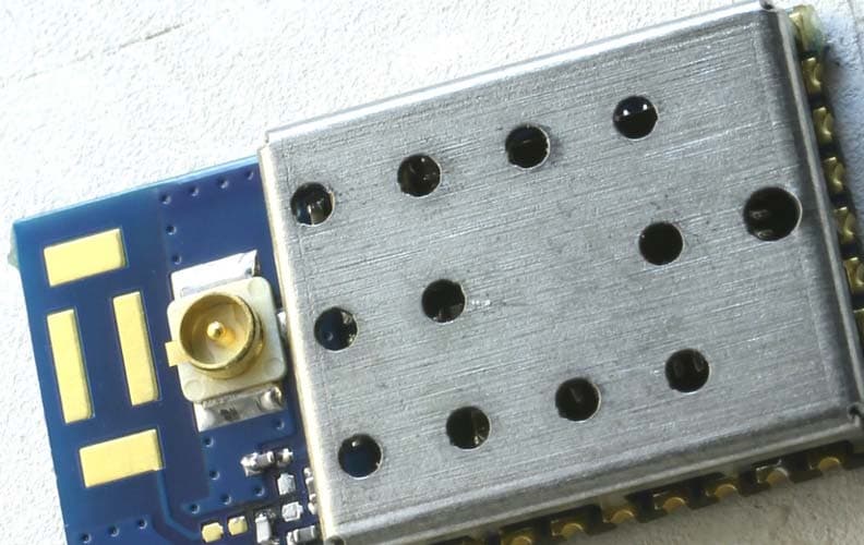
OJM900MCA
Jun 04, 2015Hummingbird MCA
Equipment Class
DSS - Part 15 Spread Spectrum Transmitter
OJM-CMD-HHTX-XXXA
Aug 11, 2010Full Size Handheld Transmitter
Equipment Class
DSC - Part 15 Security/Remote Control Transmitter
OJM-OTX-XXX-CPHSA
Apr 29, 2007Compact Handheld Transmitter
Equipment Class
DSC - Part 15 Security/Remote Control Transmitter
OJM-OTX-XXX-LRMSA
Apr 24, 2006Long-Range Handheld Transmitter
Equipment Class
DSC - Part 15 Security/Remote Control Transmitter
OJM-OTX-XXX-CPMSA
Apr 24, 2006Compact Handheld Transmitter
Equipment Class
DSC - Part 15 Security/Remote Control Transmitter