OJM900MCAHummingbird MCA
Linx Technologies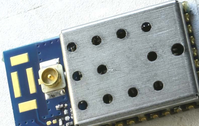
Click to zoom
Application Details
- Equipment Class
- DSS - Part 15 Spread Spectrum Transmitter
- Date of Grant
- Jun 04, 2015
- Application Purpose
- Original Equipment
- Date of Application
- Jun 04, 2015
- Equipment Note
- Hummingbird MCA
- Frequency Range
- 902.75000000 - 914.74000000
- Company
- Linx Technologies
- Country
- United States
Documents & Files
Document Text
Text extracted from the exhibit documents filed with the FCC. Open a document above to read the original.
Users Manual
HumPRO TM Series RF Transceiver Module Data Guide Table of Contents 1 Description 1 Features 2 Ordering Information 2 Absolute Maximum Ratings 3 Electrical Specifications 5 Typical Performance Graphs 10 Pin Assignments 10 Pin Descriptions 12 Pre-Certified Module Pin Assignments 13 Module Dimensions 14 Theory of Operation 15 Module Description 16 Overview 18 Addressing Modes 20 Automatic Addressing 20 Address Register Use 21 Acknowledgements and Assured Delivery 22 Frequency Hopping Spread Spectrum 23 Compatibility with the 250 Series 23 Networking 24 Transmitting Packets 25 Receiving Packets 29 Using the Buffer Empty (BE) Line 30 Exception Engine 32 Carrier Sense Multiple Access (CSMA) 33 Using the Command Response (CRESP) Line 34 Using the CMD Line 34 External Amplifier Control 35 AES Encryption Warning: Some customers may want Linx radio frequency (“RF”) products to control machinery or devices remotely, including machinery or devices that can cause death, bodily injuries, and/or property damage if improperly or inadvertently triggered, particularly in industrial settings or other applications implicating life-safety concerns (“Life and Property Safety Situations”). NO OEM LINX REMOTE CONTROL OR FUNCTION MODULE SHOULD EVER BE USED IN LIFE AND PROPERTY SAFETY SITUATIONS. No OEM Linx Remote Control or Function Module should be modified for Life and Property Safety Situations. Such modification cannot provide sufficient safety and will void the product’s regulatory certification and warranty. Customers may use our (non-Function) Modules, Antenna and Connectors as part of other systems in Life Safety Situations, but only with necessary and industry appropriate redundancies and in compliance with applicable safety standards, including without limitation, ANSI and NFPA standards. It is solely the responsibility of any Linx customer who uses one or more of these products to incorporate appropriate redundancies and safety standards for the Life and Property Safety Situation application. Do not use this or any Linx product to trigger an action directly from the data line or RSSI lines without a protocol or encoder/ decoder to validate the data. Without validation, any signal from another unrelated transmitter in the environment received by the module could inadvertently trigger the action. All RF products are susceptible to RF interference that can prevent communication. RF products without frequency agility or hopping implemented are more subject to interference. This module does have a frequency hopping protocol built in, but the developer should still be aware of the risk of interference. Do not use any Linx product over the limits in this data guide. Excessive voltage or extended operation at the maximum voltage could cause product failure. Exceeding the reflow temperature profile could cause product failure which is not immediately evident. Do not make any physical or electrical modifications to any Linx product. This will void the warranty and regulatory and UL certifications and may cause product failure which is not immediately evident. ! – – 1 Description The HumPRO TM Series is a frequency hopping spread spectrum (FHSS) transceiver designed for the reliable transfer of digital data. It has a very fast lock time so that it can quickly wake up, send data and go back to sleep, saving power in battery-powered applications. The module is available in the 915MHz frequency band. The module has several features that increase the data transfer reliability. It ensures that no other modules are transmitting before it begins transmitting data. Automatic acknowledgements ensure that the remote side received valid data. Multiple hopping patterns enable several systems to operate in proximity without interference. A standard UART interface is used for module configuration and data transfer. A few simple serial commands are all that are needed for configuration. All modules have a unique 32-bit serial number that can be used as an address. Source and destination addressing support point-to-point and broadcast links. Address masking by the receiving module allows for creating subnets. Other network topologies can also be implemented. Housed in a tiny compact reflow-compatible SMD package, the transceiver requires no external RF components except an antenna, which greatly simplifies integration and lowers assembly costs. Versions are available that have obtained FCC and Industry Canada modular certification. Features • FHSS Algorithm • Fast Lock (<30ms at 115kbps) • Low power modes • FCC and IC Pre-certified version • Simple UART interface • No external RF components required • No production tuning required • Tiny PLCC-32 footprint HumPRO TM Series RF Transceiver Module Data Guide Figure 1: Package Dimensions Revised 4/8/2015 0.45" (11.43) 0.55" (13.97) 0.07" (1.78) 38 Using the MODE_IND Line 39 Using the PB Line 40 Restore Factory Defaults 40 Using the Low Power Features 42 The Command Data Interface 43 Reading from Registers 44 Writing to Registers 45 Command Length Optimization 45 Example Code for Encoding Read/Write Commands 48 The Command Data Interface Command Set 95 Typical Applications 96 Usage Guidelines for FCC Compliance 96 Additional Testing Requirements 97 Information to the user 98 Product Labeling 98 FCC RF Exposure Statement 98 Antenna Selection 100 Castellation Version Reference Design 102 Power Supply Requirements 102 Antenna Considerations 103 Interference Considerations 104 Pad Layout 105 Microstrip Details 106 Board Layout Guidelines 107 Helpful Application Notes from Linx 108 Production Guidelines 108 Hand Assembly 108 Automated Assembly 110 General Antenna Rules 112 Common Antenna Styles 114 Regulatory Considerations – – – – 23 HumPRO TM Series Transceiver Specifications ParameterSymbolMin.Typ.Max.UnitsNotes Power Supply Operating VoltageV CC 2.03.6VDC TX Supply Currentl CCTX 900MHz at +10dBm40.541.5mA1,2 900MHz at 0dBm2224mA1,2 RX Supply Currentl CCRX 23.524.5mA1,2,3 Power-Down …
Text truncated - open the document above for the full version.
Users Manual
HumRC TM Series Remote Control and Sensor Transceiver Data Guide Table of Contents 1 Description 1 Features 2 Ordering Information 2 Electrical Specifications 4 Absolute Maximum Ratings 5 Typical Performance Graphs 10 Pin Assignments 10 Pin Descriptions 12 Theory of Operation 13 Module Description 14 Transceiver Operation 15 Transmit Operation 16 Receive Operation 16 Acknowledgement 17 Automatic Responses 17 Permissions Mask 18 The Pair Process 19 Configuring the Status Lines 19 External Amplifier Control 20 Mode Indicator 20 Reset to Factory Default 21 Using the LVL_ADJ Line 22 Receiver Duty Cycle 23 Using the LATCH_EN Line 23 Using the Low Power Features 24 Triggered Transmissions 25 Frequency Hopping 26 The Command Data Interface 28 Serial Setup Configuration for Stand-alone Operation Warning: Some customers may want Linx radio frequency (“RF”) products to control machinery or devices remotely, including machinery or devices that can cause death, bodily injuries, and/or property damage if improperly or inadvertently triggered, particularly in industrial settings or other applications implicating life-safety concerns (“Life and Property Safety Situations”). NO OEM LINX REMOTE CONTROL OR FUNCTION MODULE SHOULD EVER BE USED IN LIFE AND PROPERTY SAFETY SITUATIONS. No OEM Linx Remote Control or Function Module should be modified for Life and Property Safety Situations. Such modification cannot provide sufficient safety and will void the product’s regulatory certification and warranty. Customers may use our (non-Function) Modules, Antenna and Connectors as part of other systems in Life Safety Situations, but only with necessary and industry appropriate redundancies and in compliance with applicable safety standards, including without limitation, ANSI and NFPA standards. It is solely the responsibility of any Linx customer who uses one or more of these products to incorporate appropriate redundancies and safety standards for the Life and Property Safety Situation application. Do not use this or any Linx product to trigger an action directly from the data line or RSSI lines without a protocol or encoder/ decoder to validate the data. Without validation, any signal from another unrelated transmitter in the environment received by the module could inadvertently trigger the action. All RF products are susceptible to RF interference that can prevent communication. RF products without frequency agility or hopping implemented are more subject to interference. This module does have a frequency hopping protocol built in, but the developer should still be aware of the risk of interference. Do not use any Linx product over the limits in this data guide. Excessive voltage or extended operation at the maximum voltage could cause product failure. Exceeding the reflow temperature profile could cause product failure which is not immediately evident. Do not make any physical or electrical modifications to any Linx product. This will void the warranty and regulatory and UL certifications and may cause product failure which is not immediately evident. ! – – 1 Description The HumRC TM Series transceiver is designed for reliable bi-directional remote control applications. It consists of a highly optimized Frequency Hopping Spread Spectrum (FHSS) RF transceiver and integrated remote control transcoder. The FHSS system allows higher RF output power and, therefore, longer range than narrowband radios. It also provides much more noise immunity than narrowband radios, making the module suitable for use in noisy environments. Eight status lines can be set up in any combination of inputs and outputs for the transfer of button or contact states. A selectable acknowledgement indicates that the transmission was successfully received. Versions are available in the 902 to 928MHz and 2,400 to 2,483MHz frequency bands. Primary settings are hardware-selectable, which eliminates the need for an external microcontroller or other digital interface. For advanced features, optional software configuration is provided by a UART interface; however, no programming is required for basic operation. Housed in a compact reflow-compatible SMD package, the transceiver requires no external RF components except an antenna, which greatly simplifies integration and lowers assembly costs. Features • Low power consumption • 2 32 possible addresses • 8 status lines • Bi-directional remote control • Analog voltage and sensor inputs • Low power receive modes • Selectable acknowledgements • No external RF components required • No programming/tuning required • Serial interface for optional software operation/configuration • Tiny PLCC-32 footprint HumRC TM Series Remote Control and Sensor Transceiver Data Guide Figure 1: Package Dimensions Revised 5/14/2015 0.45" (11.43) 0.55" (13.97) 0.07" (1.78) 30 Basic Hardware Operation 32 Typical Applications 34 Power Supply Requirements 34 Antenna Considerations 35 Helpful Application Notes from Linx 36 Interference Considerations 37 Pad Layout 37 Board Layout Guidelines 39 Microstrip Details 40 Production Guidelines 40 Hand Assembly 40 Automated Assembly 42 General Antenna Rules 44 Common Antenna Styles 46 Regulatory Considerations – – – – 23 HumRC TM Series Transceiver Specifications ParameterSymbolMin.Typ.Max.UnitsNotes Power Supply Operating Voltage V CC 2.03.6VDC Peak TX Supply Currentl CCTX 2.4GHz at +1dBm2829mA1,2 2.4GHz at –10dBm1920mA1,2 900MHz at +10dBm3638.5mA1,2 900MHz at 0dBm2224mA1,2 Average TX Supply Current 2.4GHz at +1dBm2224mA1,2 900MHz at +10dBm27.528.5mA1,2 RX Supply Currentl CCRX 25.528mA1,2,3 Standby Currentl SBY 0.51.4μA1,2 Power-Down Currentl PDN 0.51.4μA1,2 RF Section Operating Frequency BandF C MHz HUM-2.4-RC24002483.5MHz HUM-900-RC-xxx902928MHz Number of Channels25 Channel Spacing HUM-2.4-RC2.03MHz HUM-900-RC-xxx500kHz Modulation Rate38.4kbps Receiver Section Spurious Emissions-47dBm Receiver Sensitivity5 HUM-2.4-RC–95–99dBm5 HUM-900-RC-xxx–94–98dBm5 RSSI Dynamic Range85dB Transmitter S…
Text truncated - open the document above for the full version.
ID Label/Location Info
1 2 6 L4 L5 NOTES: (UNLESS OTHERWISE SPECIFIED) 1. ALL DIMENSIONS ARE IN INCHES [mm]. 2. ASSEMBLY SHALL BE IN ACCORDANCE WITH IPC-A-610. 3. MANUFACTURE TO BE COMPLIANT WITH EU RoHS DIRECTIVE,USE MATERIALS THAT DO NOT CONTAIN REACH SUBSTANCES OF VERY HIGH CONCERN >1000ppm, AND USE DRC CONFLICT-FREE SOURCED MATERIALS. 4. FOR SCHEMATIC DIAGRAM REFERENCE DOCUMENT SCH-TRM-HUM-MCA. 5REMOVE COMPONENT INDICATED IN TABLE BELOW PRIOR TO PROGRAMMING. 6ASSEMBLE AND TEST PER LINX PRODUCTION TEST PROCEDURE LDC-OTP-HUM-MCA. APPLY LABEL TO METAL LID OF MODULE ORIENTED AS SHOWN. 5 5 5 REVISIONS REVDESCRIPTIONDATEAPPV AINITIAL RELEASE OF LINX INTERNAL DRAWING5-MAR-15SAH PART NUMBER ASM-HUM-900-xxx-yyy ITEM 1ITEM 2 REMOVE COMPONENT AT LOCATION: PROGRAM ASM-HUM-900-PRO-CASASY-HUM-900-MCALBL-HUM-900-PRO-CASL5PGM-900-PRO ASM-HUM-900-PRO-UFLASY-HUM-900-MCALBL-HUM-900-PRO-UFLL4PGM-900-PRO ASM-HUM-900-RC-CASASY-HUM-900-MCALBL-HUM-900-RC-CASL5PGM-900-RC ASM-HUM-900-RC-UFLASY-HUM-900-MCALBL-HUM-900-RC-UFLL4PGM-900-RC D C B A A B C D 1 2 3 4 5 6 7 8 8 7 6 5 4 3 2 1 PROJECTION: FINISH: MATERIAL: DT: 5-MAR-15 DT: 23-FEB-15 ENGR: J.KRAWCZYK DRAWN: B.MURPHY INTERPRET DIMENSIONS AND TOLERANCES PER ASME Y14.5. TOLERANCES: .X .1 .XX .01 .XXX .005 ANGLES: 1 SURFACE FINISH: 32 159 ORT LANE MERLIN, OR 97532 HUMMINGBIRD, PRECERTIFIED MODULE ASSEMBLY, 900MHz AASM-HUM-900-xxx-yyy DO NOT SCALE DRAWING REVDWG. NO.SIZE TITLE: B SCALE: 6:1 LDCFDFB_C SHEET 1 OF 1 WARNING: THIS DRAWING CONTAINS PROPRIETARY INFORMATION THAT IS THE SOLE PROPERTY OF LINX TECHNOLOGIES, AND SHALL BE TREATED AS SUCH. NO DISCLOSURE OR REPRODUCTION OF THIS DOCUMENT IS PERMITTED, IN WHOLE OR IN PART, WITHOUT THE EXPRESS WRITTEN PERMISSION OF LINX TECHNOLOGIES OR ITS DESIGNATED AGENTS.
ID Label/Location Info
SHEET 1 OF 1 LDCFDLT_B SCALE: 1:1 TITLE: SIZEDWG. NO.REV DO NOT SCALE DRAWING ANGLES: 1 DRAWN: ENGR: DT: DT: MATERIAL: FINISH: PROJECTION: : THIS DRAWING CONTAINS PROPRIETARY INFORMATION THAT IS THE SOLE PROPERTY OF LINX TECHNOLOGIES, AND SHALL BE TREATED AS SUCH. NO DISCLOSURE OR REPRODUCTION OF THIS DOCUMENT IS PERMITTED, IN WHOLE OR IN PART, WITHOUT THE EXPRESS WRITTEN PERMISSION OF LINX TECHNOLOGIES OR ITS DESIGNATED AGENTS. 159 ORT LANE MERLIN, OR 97532 LABEL, TRANSCEIVER, HUMMINGBIRD, LBL-HUM-900-PRO-CASA IC AND FCC CERTIFIED, 900MHz, PRO, CAS 0.500 [12.70] 0.400 [10.16] REVISIONS REVDESCRIPTIONDATEAPPV AINITIAL RELEASE OF LINX INTERNAL DRAWING4-MAR-15SAH TOLERANCES: .X.1 INTERPRET DIMENSIONS AND TOLERANCES PER ASME Y 14.5. .XX.01 .XXX.005 SEE NOTE 4 B.MURPHY24-FEB-15 S.HOGAN ACTUAL SIZE 4-MAR-15 4. MATERIAL: WHITE KAPTON POLYIMIDE WITH 1 MIL PERMANENT ACRYLIC ADHESIVE BACK. 5. LABEL MUST SURVIVE PROCESSING MULTIPLE REFLOW CYCLES OF 260°C PEAK TEMPERATURE FOR A MINIMUM OF 10-SECONDS. 6. INK MUST REMAIN INTACT AND IMAGE BE LEGIBLE AFTER TYPICAL ELECTRONIC MANUFACTURING CLEANING PROCESSES, INCLUDING: • DEIONOZED WATER SPRAY RINSE • APPLICATION OF ISOPROPYL ALCOHOL USING MODERATE PRESSURE AND A COTTON TIPPED APPLICATOR • APPLICATION OF ISOPROPYL ALCOHOL USING MODERATE PRESSURE AND A CLEAN GAUZE. NOTES: (UNLESS OTHERWISE SPECIFIED) 1. ALL DIMENSIONS ARE IN INCHES [mm]. 2. DIMENSIONS APPLY AFTER FINISHING. 3. MANUFACTURE TO BE COMPLIANT WITH EU RoHS DIRECTIVE, USE MATERIALS THAT DO NOT CONTAIN REACH SUBSTANCES OF VERY HIGH CONCERN >1000ppm, AND USE DRC CONFLICT-FREE SOURCED MATERIALS. Model: HUM-900-PRO-CAS FCC ID: OJM900MCA IC: 5840A-900MCA R0.015 [0.38] Model: HUM-900-PRO-CAS FCC ID: OJM900MCA IC: 5840A-900MCA
ID Label/Location Info
SHEET 1 OF 1 LDCFDLT_B SCALE: 1:1 TITLE: SIZEDWG. NO.REV DO NOT SCALE DRAWING ANGLES: 1 DRAWN: ENGR: DT: DT: MATERIAL: FINISH: PROJECTION: : THIS DRAWING CONTAINS PROPRIETARY INFORMATION THAT IS THE SOLE PROPERTY OF LINX TECHNOLOGIES, AND SHALL BE TREATED AS SUCH. NO DISCLOSURE OR REPRODUCTION OF THIS DOCUMENT IS PERMITTED, IN WHOLE OR IN PART, WITHOUT THE EXPRESS WRITTEN PERMISSION OF LINX TECHNOLOGIES OR ITS DESIGNATED AGENTS. 159 ORT LANE MERLIN, OR 97532 LABEL, TRANSCEIVER, HUMMINGBIRD, LBL-HUM-900-PRO-UFLA IC AND FCC CERTIFIED, 900MHz, PRO, UFL 0.500 [12.70] 0.400 [10.16] REVISIONS REVDESCRIPTIONDATEAPPV AINITIAL RELEASE OF LINX INTERNAL DRAWING4-MAR-15SAH TOLERANCES: .X.1 INTERPRET DIMENSIONS AND TOLERANCES PER ASME Y 14.5. .XX.01 .XXX.005 SEE NOTE 4 B.MURPHY24-FEB-15 S.HOGAN ACTUAL SIZE 4-MAR-15 4. MATERIAL: WHITE KAPTON POLYIMIDE WITH 1 MIL PERMANENT ACRYLIC ADHESIVE BACK. 5. LABEL MUST SURVIVE PROCESSING MULTIPLE REFLOW CYCLES OF 260°C PEAK TEMPERATURE FOR A MINIMUM OF 10-SECONDS. 6. INK MUST REMAIN INTACT AND IMAGE BE LEGIBLE AFTER TYPICAL ELECTRONIC MANUFACTURING CLEANING PROCESSES, INCLUDING: • DEIONOZED WATER SPRAY RINSE • APPLICATION OF ISOPROPYL ALCOHOL USING MODERATE PRESSURE AND A COTTON TIPPED APPLICATOR • APPLICATION OF ISOPROPYL ALCOHOL USING MODERATE PRESSURE AND A CLEAN GAUZE. NOTES: (UNLESS OTHERWISE SPECIFIED) 1. ALL DIMENSIONS ARE IN INCHES [mm]. 2. DIMENSIONS APPLY AFTER FINISHING. 3. MANUFACTURE TO BE COMPLIANT WITH EU RoHS DIRECTIVE, USE MATERIALS THAT DO NOT CONTAIN REACH SUBSTANCES OF VERY HIGH CONCERN >1000ppm, AND USE DRC CONFLICT-FREE SOURCED MATERIALS. Model: HUM-900-PRO-UFL FCC ID: OJM900MCA IC: 5840A-900MCA R0.015 [0.38] Model: HUM-900-PRO-UFL FCC ID: OJM900MCA IC: 5840A-900MCA
ID Label/Location Info
SHEET 1 OF 1 LDCFDLT_B SCALE: 1:1 TITLE: SIZEDWG. NO.REV DO NOT SCALE DRAWING ANGLES: 1 DRAWN: ENGR: DT: DT: MATERIAL: FINISH: PROJECTION: : THIS DRAWING CONTAINS PROPRIETARY INFORMATION THAT IS THE SOLE PROPERTY OF LINX TECHNOLOGIES, AND SHALL BE TREATED AS SUCH. NO DISCLOSURE OR REPRODUCTION OF THIS DOCUMENT IS PERMITTED, IN WHOLE OR IN PART, WITHOUT THE EXPRESS WRITTEN PERMISSION OF LINX TECHNOLOGIES OR ITS DESIGNATED AGENTS. 159 ORT LANE MERLIN, OR 97532 LABEL, TRANSCEIVER, HUMMINGBIRD, LBL-HUM-900-RC-CASA IC AND FCC CERTIFIED, 900MHz, RC, CAS 0.500 [12.70] 0.400 [10.16] REVISIONS REVDESCRIPTIONDATEAPPV AINITIAL RELEASE OF LINX INTERNAL DRAWING4-MAR-15SAH TOLERANCES: .X.1 INTERPRET DIMENSIONS AND TOLERANCES PER ASME Y 14.5. .XX.01 .XXX.005 SEE NOTE 4 B.MURPHY24-FEB-15 S.HOGAN ACTUAL SIZE 4-MAR-15 4. MATERIAL: WHITE KAPTON POLYIMIDE WITH 1 MIL PERMANENT ACRYLIC ADHESIVE BACK. 5. LABEL MUST SURVIVE PROCESSING MULTIPLE REFLOW CYCLES OF 260°C PEAK TEMPERATURE FOR A MINIMUM OF 10-SECONDS. 6. INK MUST REMAIN INTACT AND IMAGE BE LEGIBLE AFTER TYPICAL ELECTRONIC MANUFACTURING CLEANING PROCESSES, INCLUDING: • DEIONOZED WATER SPRAY RINSE • APPLICATION OF ISOPROPYL ALCOHOL USING MODERATE PRESSURE AND A COTTON TIPPED APPLICATOR • APPLICATION OF ISOPROPYL ALCOHOL USING MODERATE PRESSURE AND A CLEAN GAUZE. NOTES: (UNLESS OTHERWISE SPECIFIED) 1. ALL DIMENSIONS ARE IN INCHES [mm]. 2. DIMENSIONS APPLY AFTER FINISHING. 3. MANUFACTURE TO BE COMPLIANT WITH EU RoHS DIRECTIVE, USE MATERIALS THAT DO NOT CONTAIN REACH SUBSTANCES OF VERY HIGH CONCERN >1000ppm, AND USE DRC CONFLICT-FREE SOURCED MATERIALS. Model: HUM-900-RC-CAS FCC ID: OJM900MCA IC: 5840A-900MCA R0.015 [0.38] Model: HUM-900-RC-CAS FCC ID: OJM900MCA IC: 5840A-900MCA
ID Label/Location Info
SHEET 1 OF 1 LDCFDLT_B SCALE: 1:1 TITLE: SIZEDWG. NO.REV DO NOT SCALE DRAWING ANGLES: 1 DRAWN: ENGR: DT: DT: MATERIAL: FINISH: PROJECTION: : THIS DRAWING CONTAINS PROPRIETARY INFORMATION THAT IS THE SOLE PROPERTY OF LINX TECHNOLOGIES, AND SHALL BE TREATED AS SUCH. NO DISCLOSURE OR REPRODUCTION OF THIS DOCUMENT IS PERMITTED, IN WHOLE OR IN PART, WITHOUT THE EXPRESS WRITTEN PERMISSION OF LINX TECHNOLOGIES OR ITS DESIGNATED AGENTS. 159 ORT LANE MERLIN, OR 97532 LABEL, TRANSCEIVER, HUMMINGBIRD, LBL-HUM-900-RC-UFLA IC AND FCC CERTIFIED, 900MHz, RC, UFL 0.500 [12.70] 0.400 [10.16] REVISIONS REVDESCRIPTIONDATEAPPV AINITIAL RELEASE OF LINX INTERNAL DRAWING4-MAR-15SAH TOLERANCES: .X.1 INTERPRET DIMENSIONS AND TOLERANCES PER ASME Y 14.5. .XX.01 .XXX.005 SEE NOTE 4 B.MURPHY24-FEB-15 S.HOGAN ACTUAL SIZE 4-MAR-15 4. MATERIAL: WHITE KAPTON POLYIMIDE WITH 1 MIL PERMANENT ACRYLIC ADHESIVE BACK. 5. LABEL MUST SURVIVE PROCESSING MULTIPLE REFLOW CYCLES OF 260°C PEAK TEMPERATURE FOR A MINIMUM OF 10-SECONDS. 6. INK MUST REMAIN INTACT AND IMAGE BE LEGIBLE AFTER TYPICAL ELECTRONIC MANUFACTURING CLEANING PROCESSES, INCLUDING: • DEIONOZED WATER SPRAY RINSE • APPLICATION OF ISOPROPYL ALCOHOL USING MODERATE PRESSURE AND A COTTON TIPPED APPLICATOR • APPLICATION OF ISOPROPYL ALCOHOL USING MODERATE PRESSURE AND A CLEAN GAUZE. NOTES: (UNLESS OTHERWISE SPECIFIED) 1. ALL DIMENSIONS ARE IN INCHES [mm]. 2. DIMENSIONS APPLY AFTER FINISHING. 3. MANUFACTURE TO BE COMPLIANT WITH EU RoHS DIRECTIVE, USE MATERIALS THAT DO NOT CONTAIN REACH SUBSTANCES OF VERY HIGH CONCERN >1000ppm, AND USE DRC CONFLICT-FREE SOURCED MATERIALS. Model: HUM-900-RC-UFL FCC ID: OJM900MCA IC: 5840A-900MCA R0.015 [0.38] Model: HUM-900-RC-UFL FCC ID: OJM900MCA IC: 5840A-900MCA
RF Exposure Info
= where: S = transmitter operating variables: must be blank if dB values are entered P = = 10.34 (dBm) - or - (mW) 7 G = = 1.8 (dBi) - or - (numeric gain) R = = (cm) ( PG)/(4*R 2 * ) = (mW/cm 2 ) 10.81433951 1.51356 20 (mw) (gain) (cm) ()/(4** 3 ) = (mW/cm 2 ) = (mW/cm 2 ) SS 16.36816521 ) 400 0 003256 4* POWER DENSITY ESTIMATIONS BASED ON POWER OUTPUT, ANTENNA GAIN, AND DISTANCE FROM ANTENNA maximum power density (mW/cm 2 ) (mW/cm 2 ) ) = distance to the center of the radiation of the antenna -- >> 3.1 20 ( ( S S ( P G ) / ( 4 R 2 ) power input to the antenna --------------------------------- >> gain of the antenna - worst case -------------------------- >> 2 * / () / () = ( m W/ cm 2 ) 5026.54824 6 16.36816521 0 . 003256
Test Report
– 1 – Revised 11/18/13 Product Description HW Series ½-wave center-fed dipole antennas deliver outstanding performance in a rugged and cosmetically attractive package. The antenna contains a helical element and internal counterpoise which eliminates external ground plane dependence and maximizes performance. HW Series antennas attach via a standard SMA or Part 15 compliant RP-SMA connector. Custom colors and connectors are available for volume OEM customers. Features • Low cost • Internal counterpose • Bandwidth covers entire ISM 900MHz band • Excellent performance • Omni-directional pattern • Outstanding VSWR • Rugged & damage-resistant • Standard SMA or Part 15 compliant RP-SMA connector • Internal O-ring seal on connector Electrical Specifications Center Frequency: 916MHz Recmd. Freq. Range: 900–930MHz Wavelength: ½-wave VSWR: ≤ 2.0 typical at center Peak Gain: 1.2dBi Impedance: 50-ohms Connection: SMA or RP-SMA Oper. Temp. Range: –20°C to +85°C Electrical specifications and plots measured with a 10.16 cm x 10.16 cm (4.00" x 4.00") reference ground plane. ANT-916-CW-HW Data Sheet by Ordering Information ANT-916-CW-HW (with RP-SMA connector) ANT-916-CW-HW-SMA (with SMA connector) End View 8.1 mm (0.32") 120.0 mm (4.72") 10.7 mm (0.42") 5.6 mm (0.22") 15.5 mm (0.61") – 2 – by Data Sheet ANT-916-CW-HW VSWRReflected Power 3:1 2:1 1:1 25% 11% 0% 1016MHz816MHz 1.490 916MHz VSWR Graph What is VSWR? The Voltage Standing Wave Ratio (VSWR) is a measurement of how well an antenna is matched to a source impedance, typically 50-ohms. It is calculated by measuring the voltage wave that is headed toward the load versus the voltage wave that is reflected back from the load. A perfect match will have a VSWR of 1:1. The higher the first number, the worse the match, and the more inefficient the system. Since a perfect match cannot ever be obtained, some benchmark for performance needs to be set. In the case of antenna VSWR, this is usually 2:1. At this point, 88.9% of the energy sent to the antenna by the transmitter is radiated into free space and 11.1% is either reflected back into the source or lost as heat on the structure of the antenna. In the other direction, 88.9% of the energy recovered by the antenna is transferred into the receiver. As a side note, since the “:1” is always implied, many data sheets will remove it and just display the first number. How to Read a VSWR Graph VSWR is usually displayed graphically versus frequency. The lowest point on the graph is the antenna’s operational center frequency. In most cases, this will be different than the designed center frequency due to fabrication tolerances. The VSWR at that point denotes how close to 50-ohms the antenna gets. Linx specifies the recommended bandwidth as the range where the typical antenna VSWR is less than 2:1. 159 Ort Lane, Merlin, OR, US 97532 Phone: +1 541 471 6256 Fax: +1 541 471 6251 www.linxtechnologies.com
Test Report
– 1 – Revised 12/9/13 Product Description CW Series ¼-wave antennas deliver outstanding performance in a rugged and cosmetically attractive package. These antennas are available with standard SMA or FCC Part 15 compliant RP-SMA connectors. RP-SMA connectors allow for easy field replacement while complying with FCC requirements. A wide variety of matching connectors permit numerous mounting options. Features • Low cost • Excellent performance • Omni-directional pattern • Wide bandwidth • Very low VSWR • Fully weatherized • Flexible main shaft • Rugged & damage-resistant • SMA or Part 15 compliant RP-SMA connector • Use with plastic* or metal enclosures *Requires proximity ground plane Electrical Specifications Center Frequency: 916MHz Recom. Freq. Range: 865–965MHz Wavelength: ¼-wave Peak Gain: 1.8dBi VSWR: <1.9 typ. at center Impedance: 50-ohms Connector: RP-SMA or SMA Oper. Temp. Range: –40°C to +90°C Electrical specifications and plots measured on 10.16 cm x 10.16 cm (4.00” x 4.00”) reference ground plane ANT-916-CW-QW Data Sheet by Ordering Information ANT-916-CW-QW (with RP-SMA connector) ANT-916-CW-QW-SMA (with SMA connector) 14.5 mm (0.57") 13.0 mm (0.51") 80.0 mm (3.15") 52.0 mm (2.05") 6.0 mm (0.24") 6.4 mm (0.25") End View 7.8 mm (0.31") 4.5 mm (0.18") – 2 – Counterpoise Quarter-wave or monopole antennas require an associated ground plane counterpoise for proper operation. The size and location of the ground plate relative to the antenna will affect the overall performance of the antenna in the final design. When used in conjunction with a ground plane smaller than that used to tune the antenna, the center frequency typically will shift higher in frequency and the bandwidth will decrease. The proximity of other circuit elements and packaging near the antenna will also affect the final performance. For further discussion and guidance on the importance of the ground plane counterpoise, please refer to Linx Application Note AN-00501: Understanding Antenna Specifications and Operation. by Data Sheet ANT-916-CW-QW VSWRReflected Power 3:1 2:1 1:1 25% 11% 0% 916MHz1016MHz816MHz 1.660 VSWR Graph What is VSWR? The Voltage Standing Wave Ratio (VSWR) is a measurement of how well an antenna is matched to a source impedance, typically 50-ohms. It is calculated by measuring the voltage wave that is headed toward the load versus the voltage wave that is reflected back from the load. A perfect match will have a VSWR of 1:1. The higher the first number, the worse the match, and the more inefficient the system. Since a perfect match cannot ever be obtained, some benchmark for performance needs to be set. In the case of antenna VSWR, this is usually 2:1. At this point, 88.9% of the energy sent to the antenna by the transmitter is radiated into free space and 11.1% is either reflected back into the source or lost as heat on the structure of the antenna. In the other direction, 88.9% of the energy recovered by the antenna is transferred into the receiver. As a side note, since the “:1” is always implied, many data sheets will remove it and just display the first number. How to Read a VSWR Graph VSWR is usually displayed graphically versus frequency. The lowest point on the graph is the antenna’s operational center frequency. In most cases, this will be different than the designed center frequency due to fabrication tolerances. The VSWR at that point denotes how close to 50-ohms the antenna gets. Linx specifies the recommended bandwidth as the range where the typical antenna VSWR is less than 2:1. 159 Ort Lane, Merlin, OR, US 97532 Phone: +1 541 471 6256 Fax: +1 541 471 6251 www.linxtechnologies.com
Test Report
– 1 – Revised 12/4/13 Product Description The LP Series antennas utilize a helical element which greatly reduces the antenna’s size while allowing favorable performance characteristics. These compact antennas are cosmetically attractive and inexpensive, making them ideal for volume applications. The LP Series mounts directly to a PCB with a single screw, eliminating the expense of a connector while meeting FCC Part 15 requirements. Features • Very low cost • Compact housing • Excellent performance • Omni-directional pattern • Weather-resistant • Screw-mount • Use with plastic* or metal enclosures * Requires proximity ground plane Electrical Specifications Center frequency: 916MHz Bandwidth: 70MHz Wavelength: ¼-wave VSWR: ≤ 1.9 typical Peak Gain: 2.4dBi Impedance: 50-ohms Connection: Screw-mount Oper. Temp. Range: –20°C to +85°C Electrical specifications and plots measured with a 3.81 cm x 8.38 cm (1.5" x 3.3") reference ground plane ANT-916-PW-LP Data Sheet by Ordering Information ANT-916-PW-LP Recommended Footprint 8.89 mm (0.350”) 6.60 mm (0.260”) 5.33 mm (0.210”) 3.30 mm (0.130”) Ø3.88 mm (0.150”) ANT-xxx-PW-LP Recommended Footprint 50.5 mm (1.99") 33.5 mm (1.32") 17.0 mm (0.67") 8.0 mm (0.31") 10.4 mm (0.41") 9.5 mm (0.37") 1.7 mm (0.07") 3.7 mm (0.15") 2.3 mm (0.09") 1.5 mm (0.06") 5.3 mm (0.21") 3.2 mm (0.13") 8.0 mm (0.31") 7.4 mm (0.29") 6.0 mm (0.24") 3.1mm (0.12") 6/32 UNC – 2 – by Data Sheet ANT-916-PW-LP VSWR Graph Counterpoise Quarter-wave or monopole antennas require an associated ground plane counterpoise for proper operation. The size and location of the ground plane relative to the antenna will affect the overall performance of the antenna in the final design. When used in conjunction with a ground plane smaller than that used to tune the antenna, the center frequency typically will shift higher in frequency and the bandwidth will decrease. The proximity of other circuit elements and packaging near the antenna will also affect the…
Text truncated - open the document above for the full version.
Contact Information
Applicant
Shawn Hogan(VP of Engineering & Operations)
Technical Contact
Compatible Electronics, Inc.Kenneth Lee
[email protected]714-579-0500
114 Olinda Drive · Brea, California · United States
Test Firm
Compatible Electronics, Inc.Michael Christensen
Technical Specifications
| # | Rule Parts | Frequency Range | Power Output |
|---|---|---|---|
| 3 | 15C | 902.75 MHz - 914.74 MHz | 9.73 mW |
Other Applications from Linx Technologies

OJM-CMD-HHTX-XXXA
Aug 11, 2010Full Size Handheld Transmitter
Equipment Class
DSC - Part 15 Security/Remote Control Transmitter
OJM-OTX-XXX-CPHSA
Apr 29, 2007Compact Handheld Transmitter
Equipment Class
DSC - Part 15 Security/Remote Control Transmitter
OJM-OTX-XXX-LRHSA
Apr 11, 2007Long-Range Handheld Transmitter
Equipment Class
DSC - Part 15 Security/Remote Control Transmitter
OJM-OTX-XXX-LRMSA
Apr 24, 2006Long-Range Handheld Transmitter
Equipment Class
DSC - Part 15 Security/Remote Control Transmitter
OJM-OTX-XXX-CPMSA
Apr 24, 2006Compact Handheld Transmitter
Equipment Class
DSC - Part 15 Security/Remote Control Transmitter