OJM-OTX-XXX-LRMSALong-Range Handheld Transmitter
Linx Technologies
Click to zoom
Application Details
- Equipment Class
- DSC - Part 15 Security/Remote Control Transmitter
- Date of Grant
- Apr 24, 2006
- Application Purpose
- Original Equipment
- Date of Application
- Apr 24, 2006
- Equipment Note
- Long-Range Handheld Transmitter
- Frequency Range
- 433.92000000 - 433.92000000
- Company
- Linx Technologies
- Country
- United States
Documents & Files
Document Text
Text extracted from the exhibit documents filed with the FCC. Open a document above to read the original.
Users Manual
DESCRIPTIONThe Linx OTX-***-HH-LR8-MS Long-RangeHandheld Transmitter is ideal for general-purpose remote control and commandapplications that require longer transmissiondistances. This unit has been pre-certified forFCC Part 15, Industry Canada, and EuropeanCE (433MHz only) compliance, reducing costsand time to market. Available in 315, 418(standard), or 433.92MHz, this small remotehas a transmission range of up to 3,000 feetwhen combined with the LR Series receiver.The transmitter unit can be configured with 1 to8 buttons and the keypad and labeling can bemodified to meet specific OEM customerrequirements. Ease of use and security aredramatically enhanced by the on-board MSSeries encoder, which allows instant creation ofup to 16,777,216 (2 24 ) unique addresses without cumbersome DIP switches or cut traces.When paired with a MS Series decoder,transmitter identity can be determined andbutton permissions established. The unit uses asingle 3V CR2032 lithium button cell. FEATURES FCC, Canada, and CE pre-certified 1 to 8 buttons Small package Customizable keypad APPLICATIONS INCLUDE General Remote Control Keyless Entry Garage / Gate Openers Lighting Control Call Systems Home / Industrial Automation Wire Elimination OEM ConfigurationsWith a one-time NRE andminimum order, Linx can configurethe keypad and label areas tomeet your specific requirements.Contact Linx for details. MS LONG-RANGE HANDHELD TRANSMITTER DATA GUIDE 0.60" 0.20" 1.375"2.81" 1.62" 2.00" 1.35" R 0.2" Revised 2/28/06 Figure 1: Package Dimensions WIRELESS MADE SIMPLE PART # DESCRIPTIONOTX-***-HH-LR8-MS-xxx MS Long-Range TransmitterMDEV-***-HH-LR8-MS HH- LR8 Master Development System *** = 315, 418 (Standard), 433.92 MHzxxx = Color Leave blank for standard Black ORDERING INFORMATION Page 3 Page 2 SETTING THE TRANSMITTER ADDRESS The MS Long-Range HandheldTransmitter allows the selection of oneof 16,777,216 (2 24 ) unique addresses. All transmitters are supplied set to thesame address. To avoid contention withother units or to create uniquerelationships, the address can bechanged. This is accomplished by usinga paper clip or probe to press theCREATE_ADDR button on the boardthrough the bottom hole in the back ofthe case. When the button is depressed,a LED will light up in the MODE_INDwindow, indicating that the address is being created. The address will berandomized for as long as the button is held down. When the button is released,the randomized address is saved and the LED will begin flashing to indicate thatthe Control Permissions may now be set. Press the buttons that the transmitterwill have the authority to access. Press the CREATE_ADDR button with thepaper clip again or wait 17 seconds for it to time out. The address and ControlPermissions are now set. The decoder will need to learn the address before itwill accept any transmissions. Please see the Typical Applications section of thisdata guide or the MS Series Decoder Data Guide for details. OTX-***-HH-LR8-MS BUTTON ASSIGNMENTS This diagram illustrates the relationship between the button locations andencoder data lines. D6 D7 D4 D5 D2 D3 D0 D1 Figure 3: OTX-***-HH-LR8-MS Button Assignments Figure 2: CREATE_ADDR Button Access THEORY OF OPERATION The OTX-***-HH-LR8-MS Long-Range Handheld transmitter combines the LRSeries transmitter and an antenna with an on-board MS Series encoder to forma simple, yet highly reliable RF remote-control transmitter. The LR Seriestransmitter is a low-cost, high-performance synthesized ASK / OOK transmitter.The transmitter’s synthesized architecture delivers outstanding stability andfrequency accuracy, while minimizing the effects of antenna port loading and mismatching. This reduces or eliminates frequency pulling, bit contraction, andother negative effects that are common to SAW-based transmitter architectures,providing a significantly higher level of performance and reliability.When a button is pressed on the transmitter, power is applied to the internalcircuitry and the encoder is enabled. The encoder then detects the logic statesof the button data lines. These states are formatted into a 2-word transmissioncycle that continues until the button is released. The encoder data is used tomodulate the transmitter that, through the antenna, conveys the data into freespace. Once data is received, a decoder IC is used to check the transmitter’saddress against an address saved in memory. If a match is confirmed, thedecoder’s outputs are set to replicate the transmitter’s button states. Theseoutputs can then be used to activate external circuitry required by theapplication.The transmitter is compatible with several Linx receiver products, including theLC and LR product families. For applications where range is critical, the LRSeries receiver is the best choice due to its outstanding sensitivity. When thetransmitter is combined with an LR Series receiver and the MS Series decoder,ranges of up to 1,000 feet are possible. Appli cations operating over shorter distances will also benefit from the increased link reliability and superior noiseimmunity provided by the LR Series receiver. 1. Characterized, but not testedNotes ELECTRICAL SPECIFICATIONS PP aa rr aa mm ee tt ee rr DD ee ss ii gg nn aa tt ii oo nn MM ii nn .. TT yy pp ii cc aa ll MM aa xx .. UU nn ii tt ss NN oo tt ee ss POWER SUPPLYOperating Voltage V CC 2.1 3.0 3.6 VDC – Supply Current I CC – 3.4 – mA – Power-Down Current I PDN – 5.0 – nA 1 TRANSMITTER SECTIONTransmit Frequency Range: F C OTX-315-HH-LR8-MS – 315 – MHz – OTX-418-HH-LR8-MS – 418 – MHz – OTX-433-HH-LR8-MS – 433.92 – MHz – Center Frequency Accuracy – -50 – +50 kHz – ENVIRONMENTALOperating Temperature Range – -40 – +85 °C 1 Page 5 Page 4 B atter y W arnin g La b e l o n INSIDE of battery cove r 4 33 MHz version ONLY FCC ID: OJM -OTX -XXX-L RM SA F C C I D : O J M - O T X - X X X - L R M S A IC: 5840 A-LRM SXXX A I C : 5 8 4 0 A - L R M S X X X A 418MHz 4 1 8 M H z Figure 5: OTX-***-HH-LR8-MS Assembly INSTRUCTION …
Text truncated - open the document above for the full version.
ID Label/Location Info
575 SE ASHLEY PLACE ● GRANTS PASS, OR 97526 PHONE: (800) 736-6677 ● FAX: (541) 471-6251 The FCC and Industry Canada ID numbers for the Long Range Handheld transmitter are: FCC ID: OJM-OTX-XXX-LRMSA IC: 5840A-LRMSXXXA The label and the location on the unit are shown below. The required disclaimers will be included in the User’s Manual. The label is applied to the back of the unit. This is shown below in actual size.
Test Report
Report Number: B60303B2 FCC Part 15 Subpart B and FCC Section 15.231 Test Report Long-Range Handheld Transmitter P/N: OTX-xxx-HH-LR8-MS 114 OLINDA DRIVE, BREA, CALIFORNIA 92823 PHONE: (714) 579-0500 FAX: (714) 579-1850 Page 1 of 16 FCC PART 15, SUBPART B and C TEST REPORT for LONG-RANGE HANDHELD TRANSMITTER P/N: OTX-xxx-HH-LR8-MS Prepared for LINX TECHNOLOGIES 575 S.E. ASHLEY PLACE GRANTS PASS, OREGON 97526 Prepared by:_____________________ KYLE FUJIMOTO Approved by:____________________ BENIGNO CHAVEZ COMPATIBLE ELECTRONICS INC. 114 OLINDA DRIVE BREA, CALIFORNIA 92823 (714) 579-0500 DATE: MARCH 31, 2006 REPORT APPENDICES TOTAL BODY A B C D E PAGES 16 2 2 2 14 27 63 This report shall not be reproduced except in full, without the written approval of Compatible Electronics. Report Number: B60303B2 FCC Part 15 Subpart B and FCC Section 15.231 Test Report Long-Range Handheld Transmitter P/N: OTX-xxx-HH-LR8-MS 114 OLINDA DRIVE, BREA, CALIFORNIA 92823 PHONE: (714) 579-0500 FAX: (714) 579-1850 Page 2 of 16 TABLE OF CONTENTS Section / Title PAGE GENERAL REPORT SUMMARY 4 SUMMARY OF TEST RESULTS 4 1. PURPOSE 5 2. ADMINISTRATIVE DATA 6 2.1 Location of Testing 6 2.2 Traceability Statement 6 2.3 Cognizant Personnel 6 2.4 Date Test Sample was Received 6 2.5 Disposition of the Test Sample 6 2.6 Abbreviations and Acronyms 6 3. APPLICABLE DOCUMENTS 7 4. DESCRIPTION OF TEST CONFIGURATION 8 4.1 Description of Test Configuration - EMI 8 4.1.1 Cable Construction and Termination 9 5. LISTS OF EUT, ACCESSORIES AND TEST EQUIPMENT 10 5.1 EUT and Accessory List 10 5.2 EMI Test Equipment 11 6. TEST SITE DESCRIPTION 12 6.1 Test Facility Description 12 6.2 EUT Mounting, Bonding and Grounding 12 7. TEST PROCEDURES 13 7.1 Radiated Emissions (Spurious and Harmonics) Test 13 7.2 Radiated Emissions (Spurious and Harmonics) Test (continued) 14 7.3 Bandwidth of the Fundamental 15 8. CONCLUSIONS 16 Report Number: B60303B2 FCC Part 15 Subpart B and FCC Section 15.231 Test Report Long-Range Handheld Transmitter P/N: OTX-xxx-HH-LR8-MS 114 OLINDA DRIVE, BREA, CALIFORNIA 92823 PHONE: (714) 579-0500 FAX: (714) 579-1850 Page 3 of 16 LIST OF APPENDICES APPENDIX TITLE A Laboratory Recognitions B Modifications to the EUT C Additional Models Covered Under This Report D Diagrams, Charts, and Photos • Test Setup Diagrams • Radiated Emissions Photos • Antenna and Effective Gain Factors E Data Sheets LIST OF FIGURES FIGURE TITLE 1 Plot Map And Layout of Radiated Test Site Report Number: B60303B2 FCC Part 15 Subpart B and FCC Section 15.231 Test Report Long-Range Handheld Transmitter P/N: OTX-xxx-HH-LR8-MS 114 OLINDA DRIVE, BREA, CALIFORNIA 92823 PHONE: (714) 579-0500 FAX: (714) 579-1850 Page 4 of 16 GENERAL REPORT SUMMARY This electromagnetic emission test report is generated by Compatible Electronics Inc., which is an independent testing and consulting firm. The test report is based on testing performed by Compatible Electronics personnel according to the measurement procedures described in the test specifications given below and in the "Test Procedures" section of this report. The measurement data and conclusions appearing herein relate only to the sample tested and this report may not be reproduced without the written permission of Compatible Electronics, unless done so in full. This report must not be used to claim product endorsement by NVLAP, NIST or any other agency of the U.S. Government. Device Tested: Long-Range Handheld Transmitter P/N: OTX-xxx-HH-LR8-MS S/N: N/A Product Description: See Expository Statement. Modifications: The EUT was not modified during the testing. Manufacturer: Linx Technologies 575 S.E. Ashley Place Grants Pass, Oregon 97526 Test Dates: March 1, 2, and 3, 2006 Test Specifications : EMI requirements CFR Title 47, Part 15 Subpart B; and Subpart C, Sections 15.205, 15.209, and 15.231 Test Procedure: ANSI C63.4: 2003 Test Deviations: The test procedure was not deviated from during the testing. SUMMARY OF TEST RESULTS TEST DESCRIPTION RESULTS 1 Conducted RF Emissions, 150 kHz - 30 MHz This test was not performed because the EUT operates on batteries only and cannot be plugged into the AC public mains. 2 Radiated RF Emissions, 10 kHz - 4400 MHz Complies with the Class B limits of CFR Title 47, Part 15, Subpart B; and Subpart C, sections 15.205, 15.209, and 15.231. 3 -20 dB Bandwidth of the Fundamental Complies with the limits of Subpart C, sections 15.231 [c]. Report Number: B60303B2 FCC Part 15 Subpart B and FCC Section 15.231 Test Report Long-Range Handheld Transmitter P/N: OTX-xxx-HH-LR8-MS 114 OLINDA DRIVE, BREA, CALIFORNIA 92823 PHONE: (714) 579-0500 FAX: (714) 579-1850 Page 5 of 16 1. PURPOSE This document is a qualification test report based on the Electromagnetic Interference (EMI) tests performed on the Long-Range Handheld Transmitter P/N: OTX-xxx-HH-LR8-MS. The EMI measurements were performed according to the measurement procedure described in ANSI C63.4: 2003. The tests were performed in order to determine whether the electromagnetic emissions from the equipment under test, referred to as EUT hereafter, are within the Class B specification limits defined by CFR Title 47, Part 15, Subpart B; and Subpart C, sections 15.205, 15.209, and 15.231. Report Number: B60303B2 FCC Part 15 Subpart B and FCC Section 15.231 Test Report Long-Range Handheld Transmitter P/N: OTX-xxx-HH-LR8-MS 114 OLINDA DRIVE, BREA, CALIFORNIA 92823 PHONE: (714) 579-0500 FAX: (714) 579-1850 Page 6 of 16 2. ADMINISTRATIVE DATA 2.1 Location of Testing The EMI tests described herein were performed at the test facility of Compatible Electronics, 114 Olinda Drive, Brea, California 92823. 2.2 Traceability Statement The calibration certificates of all test equipment used during the test are on file at the location of the test. The calibration is traceable to the National Institute of Standards and Technology (NIST) . 2.3 Cognizant Personnel Linx Technologies Paul True President Justin Hopper Engineer Ammon Gomez Senior Product Engineer Compati…
Text truncated - open the document above for the full version.
Test Report
LINX TECHNOLGOIES DUTY CYCLE EXPLANATION This device transmits at a 9600 baud rate and can have a maximum 8 data bits high. Based on this calculation, the maximum calculated duty cycle using the formula on page 2 would be 48.3%. Plots of the duty cycle are given showing that the actual measured duty cycle is less than or equal to 48.3% (See the duty cycle plot exhibits, which are separate from this exhibit). However, per the FCC response, the maximum calculated duty is to be used for the purposes of testing. MS Series Encoder Data Structure The MS Series encoder is designed to securely register button presses or switch closures over a wireless link for remote contro l applications. It will turn eight parallel input lines into a secure, encoded serial bit stream output. The MS Series algorithm is designed to create a data stream with a 50% duty cycle by using the same number of high bits and low bits. Two wait times reduce this duty cycle to just below 50%. Power Up Is the SEND Line High? Send Data Logic State Description: 1 = HIGH 0 = LOW Total bits, including start and stop bits = 80 Total 1’s = 40 Total 0’s = 40 Value for each bit per baud rate: 2400bps = 417uS or 1.18% of duty cycle 9600bps = 104uS or 1.01% of duty cycle 19200bps = 52uS or 0.85% of duty cycle 28800bps = 35uS or 0.74% of duty cycle 680uS 465uS 800uS 0 01101000 1 0 10101010 1 0 01010101 1 0 00000000 1 0 11111111 1 0 11101010 1 00000000 1010 Wait Time Processing Time Wait Time Wake Noise Filter Error Check ADDR-H ADDR-M ADDR-L Data Byte Error Check 11111111 Duty Cycle = Time High Total Time 40 bits + 800uS 80 bits + 680uS + 465uS + 800uS (40*104uS) + 800uS (80*104uS) + 1,945uS 4,960uS 10,265uS = 48.3% ==
Test Report
Length of pulse (uS) How many Total time (uS) 818 1 818 102.4 1 102.4 103.2 1 103.2 808 1 808 222 1 222 110.4 2 220.8 150.8 5 754 108.4 8 867.2 256 1 256 216 2 432 324 1 324 Total on-time 4907.6 4.9076 mS / 10.76 mS = 45.61%
Test Report
Length of pulse (uS) How many Total time (uS) 822 1 822 104.4 2 208.8 810 1 810 220 2 440 112 10 1120 152.4 5 762 257 1 257 437 1 437 Total on-time 4856.80 4.85680 mS / 10.80 mS = 44.97%
Test Report
Length of pulse (uS) How many Total time (uS) 816 1 816 103.2 2 206.4 806 1 806 221 1 221 112.4 1 112.4 152.4 4 609.6 110 10 1100 256 1 256 544 1 544 365 1 365 Total on-time 5036.4 5.0364 mS / 10.72 mS = 46.98%
Contact Information
Applicant
Shawn Hogan(VP of Engineering & Operations)
Technical Contact
Compatible ElectronicsKyle Fujimoto
714-579-0500
114 Olinda Drive · Brea, California · United States
Test Firm
Compatible Electronics, Inc.Michael Christensen
Technical Specifications
| # | Rule Parts | Frequency Range | Power Output |
|---|---|---|---|
| 3 | 15.231 | 433.92 MHz - 433.92 MHz | - |
Other Applications from Linx Technologies
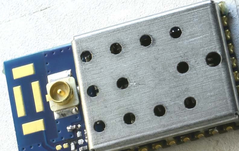
OJM900MCA
Jun 04, 2015Hummingbird MCA
Equipment Class
DSS - Part 15 Spread Spectrum Transmitter
OJM-CMD-HHTX-XXXA
Aug 11, 2010Full Size Handheld Transmitter
Equipment Class
DSC - Part 15 Security/Remote Control Transmitter
OJM-OTX-XXX-CPHSA
Apr 29, 2007Compact Handheld Transmitter
Equipment Class
DSC - Part 15 Security/Remote Control Transmitter
OJM-OTX-XXX-LRHSA
Apr 11, 2007Long-Range Handheld Transmitter
Equipment Class
DSC - Part 15 Security/Remote Control Transmitter
OJM-OTX-XXX-CPMSA
Apr 24, 2006Compact Handheld Transmitter
Equipment Class
DSC - Part 15 Security/Remote Control Transmitter