OK839285HT02900 MHz Cordless Telephone
Shenzhen Baoan Hantong Electronics Factory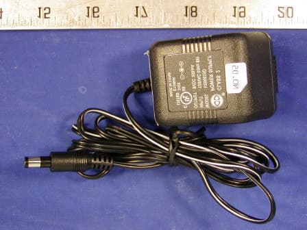
Click to zoom
Application Details
- Equipment Class
- DXX - Part 15 Low Power Communication Device Transmitter
- Date of Grant
- Jan 21, 2003
- Application Purpose
- Original Equipment
- Date of Application
- Jan 21, 2003
- Equipment Note
- 900 MHz Cordless Telephone
- Frequency Range
- 926.12000000 - 927.29000000
- Country
- China
Documents & Files
Document Text
Text extracted from the exhibit documents filed with the FCC. Open a document above to read the original.
Users Manual
39285 English I/B ver. 11182A-1 11182A-1 1 OWNER’S MANUAL # 39285 ver. 11182A-1 Page : 1 ENGLISH VERSION IMPORTANT SERVICE INFORMATION Read this manual before attempting to setup or use this instrument. It contains important information regarding safe installation and use. Keep this manual for future reference. Also save the carton, packing and proof of purchase to simplify and accelerate any needed action. If you need assistance or service, call (800) 888-8990 between 8:00 a.m. and 4:30 p.m. Pacific Standard Time, Monday through Friday. You can also visit our web site at: http://www.nwbphones.com for technical support and information on our other products. WARNING To prevent fire or shock hazard, do not expose this product to rain or any type of excess moisture. If accidentally dropped into water, the AC adaptor should immediately be unplugged from the wall along with the telephone line cord. THIS SYMBOL IS INTENDED TO ALERT THE USER OF THE PRESENCE OF IMPORTANT OPERATING AND MAINTENANCE (SERVICING) INSTRUCTIONS IN THE OWNER'S MANUAL . EXCURSION 39285 CARTON CONTENTS • Excursion ® 39285 Base and Handset • Rechargeable Ni-Cd Battery Pack • Telephone Line Cord (Short and Long) • AC Adaptor (9VDC, 350 mA, Center Positive) • User’s Manual • Warranty Card • Accessory Order Form • Wall Mount Screws and Hardware 39285 English I/B ver. 11182A-1 11182A-1 2 OWNER’S MANUAL # 39285 ver. 11182A-1 Page: 2 ENGLISH VERSION TABLE OF CONTENTS Important Service Information.........................................................................................................1 Warning..............................................................................................................................................1 Carton Contents .................................................................................................................................1 Important Safety Instructions...........................................................................................................3 Installation Precautions .....................................................................................................................4 Maintenance.......................................................................................................................................4 Battery Cautionary Instruction........................................................................................................4 FCC Notice.........................................................................................................................................4 Controls Diagram...............................................................................................................................6 Descriptions........................................................................................................................................7 Installation..........................................................................................................................................8 Battery Installation........................................................................................................................8 Belt Clip Installation ......................................................................................................................8 Wall Mounting...............................................................................................................................8 Uninstalling the Wall Mount Bracket..........................................................................................9 Power Connection ............................................................................................................................ 10 Headset Connection......................................................................................................................... 10 Initial Setup...................................................................................................................................... 10 Setting the TONE/PULSE Switch.............................................................................................. 10 Telephone Operation ........................................................................................................................ 10 Placing a Call...............................................................................................................................10 Receiving a Call........................................................................................................................... 11 Ending Calls ................................................................................................................................11 Last Number Redial.................................................................................................................... 11 Intercom Function....................................................................................................................... 12 Transfering Calls ......................................................................................................................... 12 Memory Dialing........................................................................................................................... 13 Recalling Stored Numbers.......................................................................................................... 13 Security ......................................................................................................................................... 14 Resetting Security Code and Channel Information .................................................................. 14 Multi-Channel Access.................................................................................................................. 14 Technical Information..................................................................................................................... 14 Improving Cor…
Text truncated - open the document above for the full version.
Block Diagram
39285bbd.sch-1 - Tue Nov 19 10:28:04 2002
Block Diagram
39285hbd.sch-1 - Tue Nov 19 10:29:19 2002
External Photos
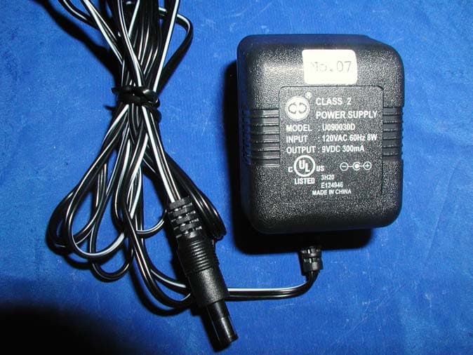
Shenzhen Baoan Hantong Electronics Factory FCC ID: OK839285HT02 Base Chassis - Front View Base Chassis - Rear View Shenzhen Baoan Hantong Electronics Factory FCC ID: OK839285HT02 Base Chassis - Top View Base Chassis - Bottom View Shenzhen Baoan Hantong Electronics Factory FCC ID: OK839285HT02 Handset Chassis - Front View Handset Chassis - Bottom View Shenzhen Baoan Hantong Electronics Factory FCC ID: OK839285HT02 Handset Chassis - Top View Handset Chassis - Left View Shenzhen Baoan Hantong Electronics Factory FCC ID: OK839285HT02 Handset Chassis - Right View AC Adapter Top View
ID Label/Location Info
EXHIBIT A - FCC PRODUCT LABELING AND WARNING STATEMENT FCC ID Label Specifications: Text is black or white in color and is left justified. Labels are silk-screened and shall be “permanently affixed” at a conspicuous location on the EUT. Proposed Label Location on EUT Bottom Side of Base/Proposed FCC Label Location Rear Side of Handset/FCC ID Location FCC Warning Statement A FCC Warning Statement is provided in the product manual. FCC ID: EW780-1005-00 This device complies with Part 15 of the FCC Rules. Operation is subject to the following two conditions: (1) this device may not cause harmful interference, and (2) this device must accept any interference received, including interference that may cause undesired operation. Privacy of communications may not be ensured when using this phone. 2.1875" 1.0" FCC ID: OK839285HT02 OK839285HT02
Internal Photos
Shenzhen Baoan Hantong Electronics Factory FCC ID: OK839285HT02 EXHIBIT C - EUT PHOTOGRAPHS Base Main Board - Component View Base Main Board - Solder View Shenzhen Baoan Hantong Electronics Factory FCC ID: OK839285HT02 Base Transmitter - Component View Base Transmitter - Solder View Shenzhen Baoan Hantong Electronics Factory FCC ID: OK839285HT02 Handset – Main Board Component View Handset – Main Board Solder View Handset – Transmitter Component View Handset – Transmitter Solder View Shenzhen Baoan Hantong Electronics Factory FCC ID: OK839285HT02 Handset – Battery View
Operational Description
LIONDA TECHNOLOGY COMPANY LIMITED ENGINEERING DEPARTMENT 39285doc.desc Page 1 1/27/2003 CIRCUIT DESCRIPTION Model: 39285 Base a. RF Transmitter Section – RF Board Compressed audio signal is frequency modulated through the varactor diode D3, D4. Diode D3, D4, L4 and Q5 the external components formed the voltage controlled oscillator circuit for the transmitter part. This circuit generates the TX VCO frequency. A portion of this signal is fed back to the PLL IC’s pin1 (FIN1) for phase comparison. Once the phase of oscillation stabilized, the PLL circuit generates the error voltage necessary for the VCO to oscillate at the desired transmitter’s RF frequency. The VCO circuit impedance is matched with the succeeding circuit through the transistor Q2 that also acts as the buffer amplifier. RF amplifier Q7 boosts the signal for transmission. This amplified RF signal is trimmed to the desired frequency band by BPF903 so as not to interfere with the receiver circuit. The transmitter RF signal is then propagated through the antenna. b. RF Receiver Section - RF Board The Base Unit antenna receives RF signal. Band Pass Filter BPF903 trims the signal to the desirable frequency band. Transistor Q6 & Q3 is a low noise amplifier that boosts the RF signal to a specific level for mixing. PLL IC1 (KB8825B) is used as a Universal Phase Lock Loop circuit. The frequency from the Voltage Controlled Oscillator (VCO) D1, L5 and Q4, is fed back to the PLL IC through pin 16 (FIN2) for phase comparison. During channel scanning or turning the unit on, once the phase of oscillation stabilized (locked), the PLL circuit generates the first local oscillator frequency for down-converting the received RF signal into the first IF frequency 10.7MHz. This process is accomplished through the IF mixer circuit Q1. Q1 is used for matching the impedance of the mixer circuit with the succeeding circuits. The resulting IF signal is kept constant by the IF Filter FL1 to 10.7MHz which is then mixed with the second local oscillator frequency 11.150MHz (derived from X1 & C47) to produced a much lower IF frequency. This lower IF frequency if further filtered by IF Filter FL4 to produce a more stable signal of 450AKHz. Quadrature signal detection is accomplished internally by the Narrow-band Detector IC2 (KA3361) with the IF coil L7. The recovered audio frequency can be taken from IC2 audio output pin9. Double conversion of received signal is utilized to improve the image frequency rejection of the unit. c. Transmitter Audio Section – Main Board 1 LIONDA TECHNOLOGY COMPANY LIMITED ENGINEERING DEPARTMENT 39285doc.desc Page 2 1/27/2003 Audio Frequency signal from the telephone line is compressed through the compressor part of IC4 to minimize the transmission noise. The degree of compression depends on the external RC combinations. AGC is also utilized by IC4 to avoid shock noise caused by abrupt change of audio levels. The compressed audio is filtered and amplified for better acoustical performance. d. Receiver Audio Section – Main Board The compressed Audio Frequency signal is passed through passive RC filters for acoustic compliance. The filtered audio is then fed to the Compander IC4 for expansion thus retrieving the original Audio signal with noise filtered out. Q5 is used as buffer circuit. Bridge rectifier D12-D15 isolates the high-voltage telephone line to the rest of the circuit. D12-D15 is also act as a hybrid transformer to create a two-way path for audio transmission to and reception from the telephone line. Handset a. RF Transmitter Section – RF Board Refer to portion 1.b for this section. All circuit performance is the same except that Band Pass Filter BPF927 is changed to BPF903 for the handset transmission. b. RF Receiver Section – RF Board Refer to portion 1.b for this section. All circuit performance is the same except that Band Pass Filter BPF903 is changed to BPF927 for the handset reception. c. Transmitter Audio Section – Main Board Audio Frequency signal from the handset or from the headset microphone is compressed through the compressor part of IC1 to minimize the transmission noise. The degree of compression depends on the external RC combinations. AGC is also utilized by IC1 to avoid shock noise caused by abrupt change of audio levels. The compressed audio is filtered and amplified for better acoustical performance. Q3 is a switching transistor that controls the power supply for the TX RF part. d. Receiver Audio Section – Main Board The compressed Audio Frequency signal is passed through passive RC filters for acoustic compliance. The filtered audio is then fed to the Compander IC1 for expansion thus retrieving the original audio signal with noise filtered out. Q2 & Q10 act as audio amplifier to sufficiently drive the handset speaker. Q7 and Q8 are 2 2 LIONDA TECHNOLOGY COMPANY LIMITED ENGINEERING DEPARTMENT 39285doc.desc Page 3 1/27/2003 switching transistors that control the power supply for the RF part, the Compander part and the AF amplifier respectively. An earphone jack is provided for an optional headset unit for handsfree conversation on the handset. OTHERS (Handset): a. Charging and Reset Controls Recharging the handset battery is accomplished by putting the handset on the cradle. IC5 detects this action and sends a command to the CPU for proper exchange of security code. b. Ring Detection When the handset receives the ring command from the base unit, the CPU will send buzzer signal to the ringer amplifier Q5 and Q6 that drives the Buzzer. OTHERS (Base): a. Hook Switching and Dialing Hook switching and the transistor Q6 that is controlled by the CPU accomplishes pulse dialing. DTMF signal from the ladder circuit internal to the CPU is filtered and amplified by Q5. b. Over-voltage Protection Fuse1 and varistor Z1 act as high current and high voltage protectors for the telephone line interface. In case of presence of voltage surge across the telephone line, Fuse1 decreases its resistance and dumps the line vo…
Text truncated - open the document above for the full version.
Operational Description
LIONDA TECHNOLOGY COMPANY LIMITED Lionda Research and Development Center 39285 TestMode.doc 1 01/27/03 Test Mode Procedure for 39285 Note: The default channel frequency is CH20 for both the Base Unit (B/U) and the Handset (H/S). Refer to the Frequency Table for proper frequency allocations. Base Basic Test Mode: Insert the 12Vdc plug into the B/U DC jack while pressing the “#” key. Both RX and TX will be activated and basic testing can be done. Press the “#” key to scan the channel frequency one at a time. Handset: Insert the battery into the H/S battery socket while pressing the “0” key. Both RX and TX will be activated and basic testing can be done. Press the “0” key to scan the channel frequency one at a time. LIONDA TECHNOLOGY COMPANY LIMITED Lionda Research and Development Center 39285 TestMode.doc 2 01/27/03 900MHz FREQUENCY CHART 39285 B A S E H A N D S E T B A S E H A N D S E T CH TX RX TX RX CH TX RX TX RX 1 902.12199 926.11750 926.11750 902.12199 21 902.72226 926.71776 926.71776 902.72226 2 902.15200 926.14751 926.14751 902.15200 22 902.75228 926.74778 926.74778 902.75228 3 902.18202 926.17753 926.17753 902.18202 23 902.78229 926.77779 926.77779 902.78229 4 902.21203 926.20754 926.20754 902.21203 24 902.81230 926.80780 926.80780 902.81230 5 902.24204 926.23755 926.23755 902.24204 25 902.84232 926.83782 926.83782 902.84232 6 902.27205 926.26757 926.26757 902.27205 26 902.87233 926.86783 926.86783 902.87233 7 902.30207 926.29758 926.29758 902.30207 27 902.90235 926.89784 926.89784 902.90235 8 902.33209 926.32759 926.32759 902.33209 28 902.93236 926.92785 926.92785 902.93236 9 902.36210 926.35760 926.35760 902.36210 29 902.96237 926.95787 926.95787 902.96237 10 902.39211 926.38762 926.38762 902.39211 30 902.99239 926.98788 926.98788 902.99239 11 902.42213 926.41763 926.41763 902.42213 31 903.02240 927.01790 927.01790 903.02240 12 902.45214 926.44764 926.44764 902.45214 32 903.05241 927.04791 927.04791 903.05241 13 902.48215 926.47765 926.47765 902.48215 33 903.08243 927.07792 927.07792 903.08243 14 902.51217 926.50767 926.50767 902.51217 34 903.11244 927.10794 927.10794 903.11244 15 902.54218 926.53768 926.53768 902.54218 35 903.14245 927.13795 927.13795 903.14245 16 902.57220 926.56770 926.56770 902.57220 36 903.17247 927.16796 927.16796 903.17247 17 902.60221 926.59771 926.59771 902.60221 37 903.20248 927.19798 927.19798 903.20248 18 902.63222 926.62772 926.62772 902.63222 38 903.23250 927.22799 927.22799 903.23250 19 902.66224 926.65774 926.65774 902.66224 39 903.26251 927.25800 927.25800 903.26251 20 902.69225 926.68775 926.68775 902.69225 40 903.29252 927.28801 927.28801 903.29252
Schematics
39285b.sch-1 - Tue Nov 19 09:52:14 2002
Schematics
39285rfb.sch-1 - Tue Nov 19 10:30:33 2002
Schematics
39285HM.SCH-1 - Tue Nov 19 09:53:49 2002
Schematics
39285rfh.sch-1 - Tue Nov 19 10:31:27 2002
Test Report
Note: This test report is specially limited to the above client company and the product model only. It may not be duplicated without prior written consent of Bay Area Compliance Laboratory Corporation. This report must not be used by the client to claim product endorsement by NVLAP or any agency of the U.S. Government. FCC PART 15 SUBPART C EMI MEASUREMENT AND TEST REPORT For Shenzhen Baoan Hantong Electronics Factory Block 11 & 12, Jinbi Industrial Area Hwangtian, Baoan, Shenzhen, China FCC ID: OK839285HT02 January 15, 2003 This Report Concerns: Original Report Equipment Type: 900MHz Cordless Telephone Test Engineer:Jeff Lee Report No.:R0211135 Test Date:December 3, 2002 Reviewed By:Benjamin Jing Prepared By:Bay Area Compliance Laboratory Corporation 230 Commercial Street Sunnyvale, CA 94085 Tel: (408) 732-9162 Fax: (408) 732-9164 Shenzhen Baoan Hantong Electronics Factory FCC ID: OK839285HT02 Report # R0211135Rpt Page 2 of 15FCC Part 15 Subpart C TABLE OF CONTENTS 1 - GENERAL INFORMATION.................................................................................................................................................3 1.1 PRODUCT DESCRIPTION FOR EQUIPMENT UNDER TEST (EUT).........................................................................................3 1.2 OBJECTIVE................................................................................................................................................................................3 1.3 RELATED SUBMITTAL(S)/GRANT(S)......................................................................................................................................3 1.4 TEST METHODOLOGY.............................................................................................................................................................3 1.5 TEST FACILITY.........................................................................................................................................................................3 1.6 TEST EQUIPMENT LIST............................................................................................................................................................4 1.7 LOCAL SUPPORT EQUIPMENT LIST AND DETAILS...............................................................................................................4 1.8 EXTERNAL I/O CABLING LIST AND DETAILS......................................................................................................................4 2 - SYSTEM TEST CONFIGURATION..................................................................................................................................5 2.1 DESCRIPTION OF TEST CONFIGURATION..............................................................................................................................5 2.2 EQUIPMENT MODIFICATIONS.................................................................................................................................................5 2.3 CONFIGURATION OF TEST SYSTEM.......................................................................................................................................5 2.4 TEST SETUP BLOCK DIAGRAM..............................................................................................................................................5 3 - CONDUCTED EMISSIONS..................................................................................................................................................6 3.1 MEASUREMENT UNCERTAINTY.............................................................................................................................................6 3.2 EUT SETUP...............................................................................................................................................................................6 3.3 SPECTRUM ANALYZER SETUP...............................................................................................................................................6 3.4 TEST PROCEDURE....................................................................................................................................................................6 3.5 SUMMARY OF TEST RESULTS.................................................................................................................................................7 3.6 CONDUCTED EMISSIONS TEST DATA....................................................................................................................................7 3.7 PLOT OF CONDUCTED EMISSIONS TEST DATA....................................................................................................................7 4 - RADIATED EMISSIONS.......................................................................................................................................................8 4.1 MEASUREMENT UNCERTAINTY.............................................................................................................................................8 4.2 EUT SETUP...............................................................................................................................................................................8 4.3 SPECTRUM ANALYZER SETUP...............................................................................................................................................8 4.4 TEST PROCEDURE....................................................................................................................................................................8 4.5 CORRECTED AMPLITUDE & MARGIN CALCULATION........................................................................................................9 4.6 SUMMARY OF TEST RESULTS.................................................................................................................................................9 4.7 RADIATED EMISSIONS TEST RESULT …
Text truncated - open the document above for the full version.
Test Setup Photos
Shenzhen Baoan Hantong Electronics Factory FCC ID: OK839285HT02 EXHIBIT B - TEST SETUP PHOTOGRAPHS Base & Handset Conducted Emission - Front View Base & Handset Conducted Emission - Rear View Shenzhen Baoan Hantong Electronics Factory FCC ID: OK839285HT02 Base Radiated Emission - Front View Base Radiated Emission - Rear View Shenzhen Baoan Hantong Electronics Factory FCC ID: OK839285HT02 Handset Radiated Emission - Front View Handset Radiated Emission - Rear View
Contact Information
Applicant
Dan Coronia(Senior Engineer)
Test Firm
Bay Area Compliance LaboratoryJohn Chan
Technical Specifications
| # | Rule Parts | Frequency Range | Power Output |
|---|---|---|---|
| 2 | 15C | 926.12 MHz - 927.29 MHz | - |
Other Applications from Shenzhen Baoan Hantong Electronics Factory
OK8ATC2488HT03
Jun 16, 20032.4 GHz 77 Chs DSSS Telephone with Caller ID
Equipment Class
DSS - Part 15 Spread Spectrum Transmitter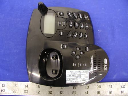
OK836882HT02
Feb 26, 20032.4 GHz Cordless Telephone
Equipment Class
DXX - Part 15 Low Power Communication Device Transmitter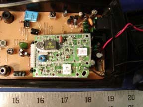
OK839287HT02
Dec 19, 2002900MHz Crdls Caller ID Phn w/ Call Waiting on H/S
Equipment Class
DXT - Part 15 Low Power Transceiver, Rx Verified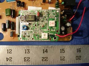
OK836280HT02
Dec 19, 20022.4GHz Filtered TM Snd 50-Chnnl Autoscan Crdls Phn
Equipment Class
DXT - Part 15 Low Power Transceiver, Rx Verified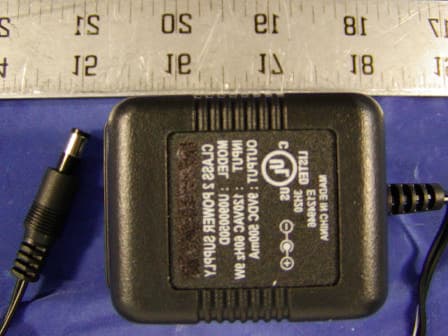
OK8TC996HT02
Nov 07, 20022.4 GHz Cordless Telephone
Equipment Class
DXX - Part 15 Low Power Communication Device Transmitter