OK8ATC2488HT032.4 GHz 77 Chs DSSS Telephone with Caller ID
Shenzhen Baoan Hantong Electronics Factory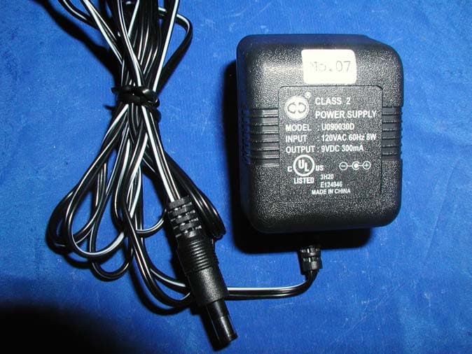
Click to zoom
Application Details
- Equipment Class
- DSS - Part 15 Spread Spectrum Transmitter
- Date of Grant
- Jun 16, 2003
- Application Purpose
- Original Equipment
- Date of Application
- Jun 16, 2003
- Equipment Note
- 2.4 GHz 77 Chs DSSS Telephone with Caller ID
- Frequency Range
- 2402.30400000 - 2480.58000000
- Country
- China
Documents & Files
Document Text
Text extracted from the exhibit documents filed with the FCC. Open a document above to read the original.
Users Manual
DSST~MAN~ATC.qxd 4/24/2003 5:14 PM Page 1 Special FeaturesSpecial Features When examining your new ATC cordless telephone, you will find an array of special features including: Digital Spread Spectrum Technology - Utilizes a “wider frequency band” for a more secure conversation with a clarity of digital sound, extended range, and minimal interference from other cordless telephones. 77 Channel Auto-hop- When interference is received, the telephone automatically hops to the clearest channel. Long Distance Service -Use the button to access special services such as Long Distance Service provided by your telephone company. Tone or Pulse Dialing- Use this phone for either TONE (push-button) or PULSE (rotary) dialing. Automated Functions - Redial the last number called and automatic STANDBY mode. Security- Ensures greater privacy because of a built-in security code with 4,000,000 possible combinations that prevents use of your telephone line by another nearby cordless phone. Special Services- Use the button to access special services such as Call Waiting supplied by your telephone company or company switchboard. STANDBY Mode- When in STANDBY mode (ON-HOOK), the phone is capable of receiving a call. When the HANDSETis on the BASE UNIT, it is automatically in the STANDBY mode (ON- HOOK). When the HANDSETis taken off the BASE UNIT, it remains in the STANDBY mode until you activate the button. Battery Power Saver- Recharge your BATTERYPACK many times with the built-in CHARGER. Once fully charged, in STANDBY mode, the HANDSET can receive/send calls for a maximum of ten days without the need for recharging. Length of charge depends on frequency of use. Luminous LCD Screen- The LCD Screen emits light for 5 seconds everytime you press any of the TELEPHONE KEYPAD buttons. HANDSET Ringer Level- Select the ringer sound level (HI, LOW, OFF). HANDSET Ringer Melody- Select the desired ringer melody from the 10 available melodies. HANDSET Volume Control- During TALK mode, press the SCROLL UP or DOWN button to select the desired receiver volume setting from Low, Medium, High, or Maximum. Alarm Clock- The telephone emits a distinctive sound when the ALARM CLOCK function is activated (See page 24). BELT CLIP- Use the BELTCLIP to hang your HANDSET on your belt. EDIT/FLASH TALK L.D.S. DSST~MAN~ATC.qxd 4/24/2003 5:14 PM Page 2 Special Features CALLER ID SYSTEM Multi-Function Large LCD Screen- Shows the number you are dialing and, with Caller ID service (available through subscription from your local telephone company), displays information about the caller before you answer the call. Name and Number DIRECTORY (PHONE BOOK) - Stores up to 40 names and numbers so that you can call them with a single key stroke. Caller List- Available with Caller ID service. Stores up to 50 calls to keep track of everyone you called. The name, phone number, time and date of the call are recorded. Allows you to return their calls with a few key strokes. Outgoing Call Memory- The telephone stores the last 8 OUTGOING CALLS to keep track of the one you called. The phone number, time, date, and the duration of the call are recorded. Allows you to call them again with a single key stroke. Preferred Calls - You can mark the name and number of a welcome caller in the DIRECTORY (PHONE BOOK). When that number calls in, the caller’s name will appear on the LCD Screen and a special ring will sound or a selected PREFERRED RING MELODY will be heard. Blocked Calls - You can mark the name and number of an unwelcome caller in the DIRECTORY (PHONE BOOK). When that number calls in, the caller’s name will appear on the LCD Screen and the ringer will be disabled. Repeat Call Indicator- Shows if a new incoming call has called more than once. Out of Area Call Indicator- Advises you that the incoming call is not in a Caller ID service area. Unavailable Call Indicator- Advises you that the origin of the incoming call does not support the Caller ID system. Call Waiting Service- Displays the name and number of the second caller, if you have subscribed to Call Waiting service from your local telephone company (see page 11.) MULTI-HANDSET, MULTI-BASE UNIT SYSTEM Multi-HANDSET- Registers a total of 9 HANDSETSinto the operating system. Multi-BASEUNIT -The user can have the option to add another BASEUNIT. The system supports 2 BASEUNITSconnected to separate telephone lines. Once registered, the HANDSETScan link to either of the BASE UNITSto make and/or receive a call. Automatic Linking - All 9 HANDSETS can register to the twoBASE UNITS (B1, B2). When the FIRST BASEUNIT (B1)is already engaged, the other HANDSETScan automatically link to the SECOND BASEUNIT (B2)by pressing the button. Intercom Call- A HANDSETcan make an INTERCOM call to the other HANDSETS in the system. Call Transfer- During a telephone conversation, the call can be transferred from one HANDSETto another HANDSET. Extension Phone Detection- When one HANDSETis connected to a BASEUNIT, the LCD Screen of the other HANDSETSthat are linked to the same BASEUNITwill display “Ext in-use.” TALK DSST~MAN~ATC.qxd 4/24/2003 5:14 PM Page 3 HANDSET ControlsHANDSET Controls DSST~MAN~ATC.qxd 4/24/2003 5:14 PM Page 4 HANDSET Controls 4./MENUButton:(Long Distance Service) During TALK mode, press to automatically access the telephone company L.D.S. service. (MENU) Press to accessthe special functions operation STANDBY mode. (For special functions see pages 18~24.) 5.TELEPHONE KEYPAD to Buttons: Allows you to make a call depending on pressed button. (For TELEPHONE KEYPAD characters, see page 15.) 6.TEMPORARY TONE Button:Press to temporarily change the DIALING mode from PULSE to TONE for Rotary Service Users. (Press once before entering numbers to access the answering system or electronic banking services, etc.) 7.Button:(EDIT) Press to edit listed items. (FLASH) Press to answer a call if you have Call Waiting. 8.BATTERY CHARGE INDICATOR:Indicates the battery charge condition as: - Low Battery Level (2 bars blinking). See p…
Text truncated - open the document above for the full version.
Block Diagram
LIONDA TECHNOLOGY CO., LTD.TITLE: ATC2488 DSS B/M BDDRAWNDATE: 04/28/03Dan APPROVED CHECKEDPAGE: REV: 01 1OF1 CPU X’TAL X2 5.1612MHz CODEC X’TAL X3 16.384MHz RING DETECT DATA BUS SURGE PROTECT CHARGE DETECT L3 L4 LINE INTERFACE CODE CLOCK CPU RESET DSP CODEC RESET RF POWER CONTROL VOLTAGE REGULATOR T/P CONTROL AC/DC 12V DC ADAPTOR TRANSMITTER RECEIVER R2D2 C7 C8 GND GND GND GAUSE FILTER CPU CODEC DSP X’TAL 19.2MHz X1 LED1 GND R12 IN USE/CHG PAGE SW2 D4 C34 GND GND 2 1 CONTROL BUS DSP INTERF ACE SSP BUS PLL INTERFACE GND TX POWER (RF POWER) ENABLE PLL-SW. RX / TX CONTROL RX DATA RSSI CPU POWER TIP RING RF CONNECTOR TX DATA MODULATION DSP RESET LIONDA TECHNOLOGY CO., LTD.TITLE: ATC2488 DSS H/M BDDRAWN APPROVED CHECKED DATE: PAGE: REV: 01 1OF1 Dan CODEC X’TAL X3 16.384MHz DATA BUS CPU X’TAL X2 5.1612MHz CHARGE DETECT CODE CLOCK CPU RESET DSP CODEC RESET REGULATOR RING ON/OFF CONTROL GND GAUSE FILTER CPU CODEC DSP X’TAL 19.2MHz X1 GND CONTROL BUS DSP INTERF ACE SSP BUS PLL INTERFACE TX POWER (RF POWER) ENABLE PLL-SW. RX / TX CONTROL RX DATA RSSI RF CONNECTOR TX DATA MODULATION DSP RESET 123 6 5 47 8 9 Talk # 0 * Memo Flash Mute Tone Re/Pa CHARGE PROTECT POLARITY L3 L4 D4 GND C34 CPU POWER RF POWER CONTROL 3.0V GND C3 SPKR POWER DRIVERBUZZER AMPLIFIER SPKR MIC1 BUZZER SPEAKER GNDGNDGND MIC V REFERENCE 3.0V LED7 IN USE/BATLOW R57 04/28/03 Dan LIONDA TECHNOLOGY CO., LTD.TITLE: ATC2488 DSS RF BM/HM BDDRAWN APPROVED CHECKED DATE: PAGE: REV: 01 1OF1 Dan 3.6V DC BASEMAIN / HANDYMAIN ANT 3.0V REGULATOR TX POWER CONTROL Q6 & Q7 POWER CONTROL TX POWER RF PWR MODULA TION TX DATA RX DATA SQ CONTROL 04/28/03 LNA 1 Q4 FT2 2442P LNA 2 Q5 FT1 2442P BIAS CONTROL RX POWER CONTROL AMPLIFIER Q3 PRE-AMPLIFIER Q2 FREQUENCY TRIPLER Q1 D1D2 LEDATACLOCK Ml2725 IC1 NOTE: THIS IC INCLUDE THE FOLLOWING FUNCTION: - PLL- IF CIRCUITS- CONTROL LOGIC-TXDATAFILTER-TXRFBUFFER- QUADRATURE DIVIDED BY 2 .. 1.6GHZ VCO
External Photos
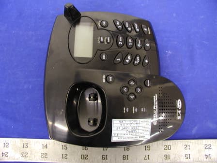
APPENDIX C - EUT EXTERNAL PHOTOGRAPHS Base - Top View Base - Bottom View Handset - Top View Handset - Back View Adaptor View
ID Label/Location Info
APPENDIX A - FCC PRODUCT LABELING AND WARNING STATEMENT FCC ID Label Specifications: Text is black or white in color and is left justified. Labels are silk-screened and shall be “permanently affixed” at a conspicuous location on the EUT. Proposed Label Location on EUT Bottom Side of Base/Proposed FCC ID Back Side of Handset/Proposed FCC ID FCC ID: OK8ATC2488HT03 This device complies with Part 15 of the FCC Rules. Operation is subject to the following two conditions: (1) this device may not cause harmful interference, and (2) this device must accept any interference received, including interference that may cause undesired operation. Privacy of communications may not be ensured when using this phone.
Internal Photos
APPENDIX C - EUT INTERNAL PHOTOGRAPHS Base – Housing and Main Board Component View Base – Housing and Main Board Solder View Base - Transceiver Component View Base - Transceiver Solder View Handset – Housing and Board Component View Handset – Housing and Main Board Solder View Handset - Transceiver Component View Handset - Transceiver Solder View Handset Antenna Connection
Operational Description
LIONDA TECHNOLOGY COMPANY LIMITED Lionda Rsearch and Development Center ATC2488DSSseries Page 1 4/28/2003 CIRCUIT DESCRIPTION Model: ATC2488 – Digital Spread Spectrum Cordless Phone Equipment Description: The device is a digital spread spectrum cordless telephone, which meets with FCC Part 15 and 68 requirements. This device is a telephone terminal that is designed for voice operation in a similar fashion to an ordinary residential or business telephone without the inconvenience and restrain of a handset cord. This device consists of a base unit and a handset. The base unit is intended to connect to standard telephone modular jacks and is supplied electric power from a standard AC power line by using with the AC adapter. The handset is powered from an internal battery pack. 1. Transmission: ADPCM CODEC converts the voice signal into 32kbps digital data. The digital data is fed to differential encoder, spreader that is responsible for the Spread Spectrum Modulation. The CD/SS Chip sends out digital data, which is made by the spread spectrum sequence. This data having 1.366Mbps data rate is filtered and upper converted to RF by FSK (Frequency Shift Keying) modulator. Then, filtered by LPF (Low Pass Filter) to suppress the spurious of the antenna transmission signal. 2. Reception: The receiver is direct conversion type. The incoming signal is passes through the RF BPF (Band Pass Filter). Down-conversion to quadrature base band signal is done using RF IC ML2725 for the LO (Local Oscillator). The CD/SS Chip calculates the correlation from the spreading code and the outputs the detected voice data to ADPCM CODEC. Finally, the ADPCM CODEC outputs received analog signal. 3. Duplexing: This device can communicate by using Time Division Duplex. It uses same frequency in both transmission and reception. It has 2.35 msec time frame of one transmission and reception cycle. This frame signal is generated by CD/SS Chip and is provided to all circuits. 4. Control: The CPU controls the RF frequency channel, and the ASIC controls ADPCM CODEC and audio signal switching also set up the spreading code. Before established the communication link, this device searches clearest available RF channel and then transmits RF signal at the clearest available channel. The CPU generates a random security code out of more than 4 million codes, which can protects customer’s privacy. Specification: • Frequency: 2402.304 ~ 2480.128 MHz • Channel: 77 • Channel Separation: 1.024MHz • Spread Spectrum Modulation Method: FSK (Frequency Shift Keying) • RF Output Power: 0.065 Watts • Duplexing: TDD (Time Division Duplex) • Burst Frame (RX/TX): 2.35msec / 2.35msec • Spread Rate: 32 – Chip per Symbol • Data Rate per Symbol: 3 Bit / Symbol • Average Chip per Data Bit: 32 (Chip / Symbol) / 3 (Bit / Symbol) = 10.667 Chip per Bit • Symbol Rate at 19.2MHz Master Clock: 23.4us (micro second) per Symbol • Chip Rate: 1.366Mbps • Voice Coding: ADPCM (Adaptive Differential Pulse Code Modulation) • Power Supply: 3.6VDC, 800mAh (Handset) / 120VAC 500mA (Base Unit)
Schematics
9702bm.sch-1 - Tue Jun 04 18:41:29 2002 ATC2488 DSS CID HANDSET SCHEMATIC 04-28-03 SHENZHEN BAOAN HANTONG ELECTRONICS FACTORY
Test Report
Note: This test report is specially limited to the above client company and the product model only. It may not be duplicated without prior written consent of Bay Area Compliance Laboratory Corporation. This report must not be used by the client to claim product endorsement by NVLAP or any agency of the U.S. Government. FCC PART 15 Subpart C EMI MEASUREMENT AND TEST REPORT For Shenzhen Baoan Hantong Electronics Factory Block 11 & 12, Jinbi Industrial Area, Hwangtain, Baoan, Shenzhen, China FCC ID: OK8ATC2488HT03 2003-06-09 This Report Concerns: Original Report Equipment Type: 2.4GHz Cordless Caller ID Telephone System Test Engineer: Ming Jing / Report Number: R0304234 Test Date: 2003-05-11 Reviewed By: Ling Zhang / Prepared By: Bay Area Compliance Laboratory Corporation 230 Commercial Street Sunnyvale, CA 94085 Tel: (408) 732-9162 Fax: (408) 732 9164 Shenzhen Baoan Hantong Electronics Factory FCC ID: OK8ATC2488HT03 Report # R0304234Rpt.doc Page 2 of 42 FCC Part 15.247 Test Report TABLE OF CONTENTS 1 - GENERAL INFORMATION..................................................................................................................................4 1.1 PRODUCT DESCRIPTION FOR EQUIPMENT UNDER TEST (EUT) ..............................................................................4 1.2 OBJECTIVE.............................................................................................................................................................4 1.3 RELATED SUBMITTAL(S)/GRANT(S).......................................................................................................................4 1.4 TEST METHODOLOGY............................................................................................................................................4 1.5 TEST FACILITY.......................................................................................................................................................4 1.6 TEST EQUIPMENT LIST...........................................................................................................................................5 1.7 LOCAL SUPPORT EQUIPMENT.................................................................................................................................5 1.8 EXTERNAL I/O CABLING LIST AND DETAILS.........................................................................................................6 2 - SYSTEM TEST CONFIGURATION.....................................................................................................................7 2.1 DESCRIPTION OF TEST CONFIGURATION................................................................................................................7 2.2 EQUIPMENT MODIFICATIONS.................................................................................................................................7 2.3 CONFIGURATION OF TEST SYSTEM.........................................................................................................................8 2.4 TEST SETUP BLOCK DIAGRAM...............................................................................................................................8 3 - SUMMARY OF TEST RESULTS..........................................................................................................................9 4 - CONDUCTED OUTPUT POWER MEASUREMENT......................................................................................10 4.1 STANDARD APPLICABLE......................................................................................................................................10 4.2 MEASUREMENT PROCEDURE................................................................................................................................10 4.3 MEASUREMENT RESULT......................................................................................................................................10 5 - 6 DB BANDWIDTH...............................................................................................................................................14 5.1 STANDARD APPLICABLE......................................................................................................................................14 5.2 MEASUREMENT PROCEDURE................................................................................................................................14 5.3 MEASUREMENT DATA..........................................................................................................................................14 6 - SPURIOUS EMISSION.........................................................................................................................................18 6.1 STANDARD APPLICABLE......................................................................................................................................18 6.2 MEASUREMENT PROCEDURE................................................................................................................................18 6.3 MEASUREMENT DATA..........................................................................................................................................18 7 - 100 KHZ BANDWIDTH OF BAND EDGES MEASUREMENT......................................................................22 7.1 STANDARD APPLICABLE......................................................................................................................................22 7.2 MEASUREMENT PROCEDURE................................................................................................................................22 7.3 TEST RESULTS.....................................................................................................................................................22 8 - POWER SPECTRAL DENSITY ..........................................................................................................................27 8.1 STANDARD …
Text truncated - open the document above for the full version.
Test Setup Photos
APPENDIX B - TEST SETUP PHOTOGRAPHS Base Conducted Emission Base Radiated Emission Handset Radiated Emission
Contact Information
Applicant
Dan Coronia(Senior Engineer)
Test Firm
Bay Area Compliance LaboratoryJohn Chan
Technical Specifications
| # | Rule Parts | Frequency Range | Power Output |
|---|---|---|---|
| 2 | 15C | 2.40 GHz - 2.48 GHz | 1.70 mW |
Other Applications from Shenzhen Baoan Hantong Electronics Factory
OK836882HT02
Feb 26, 20032.4 GHz Cordless Telephone
Equipment Class
DXX - Part 15 Low Power Communication Device Transmitter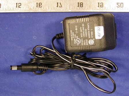
OK839285HT02
Jan 21, 2003900 MHz Cordless Telephone
Equipment Class
DXX - Part 15 Low Power Communication Device Transmitter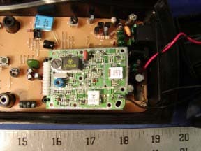
OK839287HT02
Dec 19, 2002900MHz Crdls Caller ID Phn w/ Call Waiting on H/S
Equipment Class
DXT - Part 15 Low Power Transceiver, Rx Verified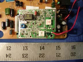
OK836280HT02
Dec 19, 20022.4GHz Filtered TM Snd 50-Chnnl Autoscan Crdls Phn
Equipment Class
DXT - Part 15 Low Power Transceiver, Rx Verified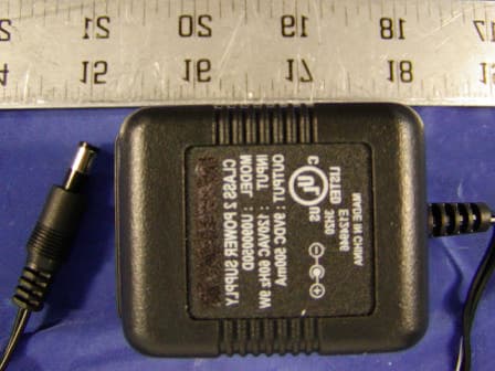
OK8TC996HT02
Nov 07, 20022.4 GHz Cordless Telephone
Equipment Class
DXX - Part 15 Low Power Communication Device Transmitter