OKRMX800ABRepeater/Base Station
Spectra Engineering PTY LTD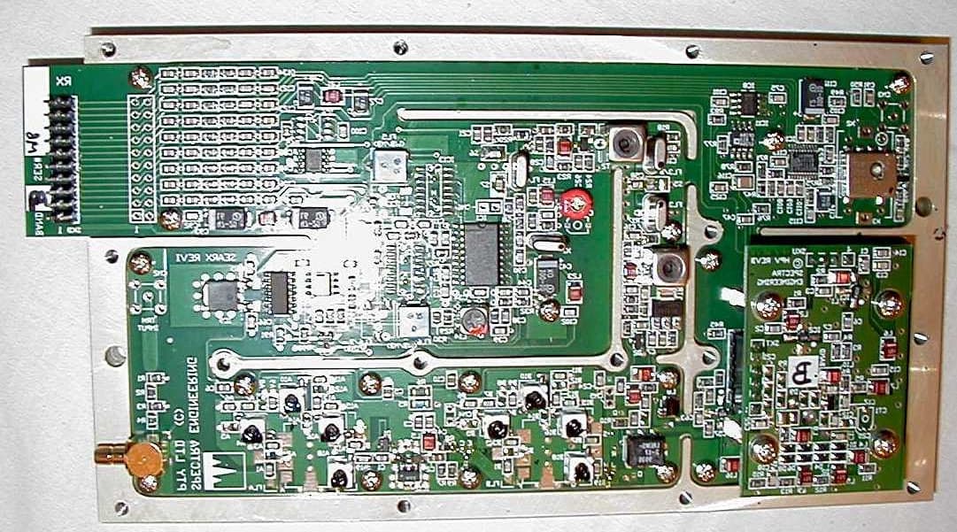
Click to zoom
Application Details
- Equipment Class
- TNB - Licensed Non-Broadcast Station Transmitter
- Date of Grant
- May 17, 2001
- Application Purpose
- Original Equipment
- Date of Application
- Mar 26, 2001
- Equipment Note
- Repeater/Base Station
- Frequency Range
- 72.00000000 - 76.00000000
- Company
- Spectra Engineering PTY LTD
- Country
- Australia
Documents & Files
Document Text
Text extracted from the exhibit documents filed with the FCC. Open a document above to read the original.
Users Manual
4. Technical Description The internal design of the MX800 is of a modular nature allowing for simple configuration and maintenance while ensuring minimal downtime. For reference purposes, the top view of a typical MX800 with top cover removed is shown below. The standard unit without speaker and microphone is illustrated. MX800 top view. PA Module Exciter Module Micro Controller Board Receiver Module 4.1. Exciter Module Refer. Exciter Block Diagram: BD002 Exciter Circuit Diagram: CS002-1 TX VCO Circuit Diagram: CS004-1 (Bands A to Q) RF from the VCO on SKU-1 at a nominal level of+3dBm is applied to the fractional-N synthesizer ICI0 main divider input. This signal is compared with the reference oscillator frequency and the correction voltage from the synthesizers charge pump output is filtered then amplified by the non inverting low noise op amp IC9A. This correction voltage is fed back to the VCO to maintain loop lock as well as being fed to the Micro Controller via SKD-14. A lock detect signal from IC10 is also fed to the Micro Controller via SKD- 16. The op amp uses a 25 volt power supply (generated on the Micro Controller) so as to provide a wide tuning range voltage to the frequency control varicaps located on the VCO board. Frequency programming data for the exciter is sent to the synthesizer chip from the Micro Controller via a serial data line on SKD-18 under the control of the Clock (SKD-15) and Strobe (SKD-17) lines. Provision is made for the optional injection of an external reference frequency. If this option is selected CN3 is fitted and X1 is not fitted. Components R30 and TR7 are also omitted. A second RF output from the VCO on SKT-6 also at +3dBm is used as the main transmit RF amplifier signal source. This main signal is first buffered by a very high isolation circuit consisting ofa 10dB pad and a MMIC amplifier (IC1). The signal is further amplified by IC2 and a variable gain wide band amplifier with 40dB control range and power output of 300mW. The drive power of this stage is used to set the output power to the main power amplifier under the control of the DC voltage on SKD-4 from the Micro Controller board. The VCO boards and synthesizer circuits are the same for the exciter and receiver modules. The VCO consists ofa 10mm ceramic coaxial resonator with common base oscillator for low phase noise for bands 805-960 MHz. Frequencies below 520 MHz use an LC tank circuit. The power supply to the VCO consists of an 8 volt regulator and active filter for maximum noise rejection. It is controlled by the Micro Controller through SKD-7 which connects to switch TR6. For standard modulation, transmit audio is fed on SKD-8 to the conventional point of the VCO varactor. For 2 point modulation, audio is also fed via SKD-19 to the voltage control pin of the VC-TXCO, this in effect cancels out the PLL error that would otherwise have occurred for low audio frequencies, hence resulting in a flat VF response. 4.2. Receiver Module Refer: Receiver Block Diagram: BD001 Receiver Front End Circuit Diagram: CS003-2 Receiver IF Circuit Diagram: CS003-1 RX VCO Circuit Diagram: CS005-1 (Band A to Q) CS012-1 (Band R to X) The receive signal from the antenna enters on CN1 a 3 section Bandpass filter which provides the initial filtering for the front end amplifier. The front end amplifier IC12 is a broad band high performance MMIC with a gain of 18dB, noise figure of 4dB and 3rd order intermodulation intercept of+36dB. This is followed by a 4dB pad and a second 3 section BPF, and a high level double balanced mixer M1. The receiver uses high side local oscillator injection for bands A to I and low side injection for all other bands. RF from the VCO main output on SKT-6 is buffered and amplified to + 17dBm by IC4 and injected in the high level mixer which down converts the signal to the first IF frequency of 90 MHz (45MHz for bands A to D3). This IF signal from the mixer is terminated by a bi-directional constant impedance network and is then amplified by a hipolar amplifier TR2 with a gain of 15dB and 3rd order intermodulation intercept +35dB. This provides a high degree of intermodulation rejection for the receiver. This stage is followed by a 4 pole 90 MHz crystal filter FL3A/B with its associated matching networks. The signal is further amplified and filtered by a transistor amplifier TR3 and its associated 2 pole crystal filter FL4 before being fed into the main IF demodulator chip IC 1 with a second IF frequency of 455kHz. The resulting audio is passed out to the Micro Controller board on SKD-3. The Received Signal Strength Indication (RSSI) from IC1 is buffered by IC5A and connected to the Micro Controller board via SKD-4. RF from the VCO on SKU-1 at a nominal level of+3dBm, is applied to the fractional-N synthesizer (IC10) main divider input. This signal is compared with the reference oscillator frequency and the correction voltage from the synthesizer's charge pump output is filtered then amplified by the non inverting low noise op amp (ICI 1A). This correction voltage is fed back to the VCO to maintain loop lock as well as being fed to the Micro Controller via SKD44. A lock detect signal from IC10 is also fed to the Micro Controller via SKD-I6. The op amp uses a 25 volt power supply (generated on the Micro Controller) so as to provide a wide tuning range voltage to the frequency control varicaps located on the VCO board. Frequency programming data for the receiver is sent to the synthesizer chip from the Micro Controller via the a serial data line on SKD-18 under the control of the Clock (SKD- 15) and Strobe (SKD- 17) lines The local oscillator signal to the mixer is controlled by the Micro Controller through an enable signal on SKD-8. This signal switches the supply to the local oscillator amplifier and is used to enable or disable the receiver. Provision is made for the optional injection of an external reference frequency. If this option is selected CN3 is fitted. 4.3. Power Amplifier Modu…
Text truncated - open the document above for the full version.
Users Manual
5. Alignment and Testing The MX800 test and alignment procedures are divided into two main sections. The first section is a transceiver level procedure which assumes that the radio is fitted with working modules. The second section contains the individual module test procedures. 5.1. Transceiver Setup, Calibration and Alignment This section explains how to setup, calibrate and align the complete MX800 Base Station. A number of procedures are required to fully initialise the MX800. The following test equipment will be needed: 1.0 MXTOOLS (MX800 Base Station Programming Utility) 2.0 MXTOOLS User Manual 3.0 RF Test Set (HP 8920) or equivalent 4.0 CRO (Cathode Ray Oscilloscope) 5.0 RF Power Meter (Watts) 6.0 RF Signal Generator 7.0 Multimeter 8.0 +13.8 VDC @ 15 amp power supply The order of some, but not all, of the procedures is important to ensure correct setup of the radio. The order of the procedures as described is recommended and those that are critical are mentioned. If the radio has been previously setup and the dealer intends to recalibrate and align the radio then steps 5.1.1, 5.1.2 and 5.1.3 can be ignored as the model number, serial number, configuration and channel information will have already been loaded. 5.1.1. Sending Model Number and Serial Number to the Radio The model number is entered or updated using MXTOOLS. To edit the model number select 'Radio Model Number', under the 'Setup' menu. This brings up a dialog box that the dealer can then enter the model number, according to the configuration of the radio. (Refer to the MXTOOLS User Manual for additional help) The dealer cannot alter the serial number as this is factory set. 5.1.2. Sending Configuration Information Firstly the configuration file for the radio needs to be setup. Using MXTOOLS the configuration information needs to be filled out on the Configuration Screen. This information needs to be saved to a configuration file. If an existing radio already contains the desired configuration then this configuration can be downloaded and saved. This configuration information then needs to be 'Sent to the MX800'. (Refer to the MXTOOLS User Manual for additional help) A warning message will appear that indicates that the MX800 Base Station has not yet been calibrated, this may be ignored. Once the configuration information has been sent then all of the programmable parameters within the MX800 Base Station are initialized. 5.1.3. Sending Channel Information The channel information setup is similar to that of the configuration. The channel frequencies, subtones and other parameters are setup in the Channel Screen in MXTOOLS. At this stage it is not necessary to set the values of the digital potentiometers. This will be done in the following procedures. After entering in the channel details this information then needs to be saved to a file. If another radio already contains the desired frequencies then these can be downloaded from that radio and saved to a file. The digital potentiometer values from one radio to the next will differ so it is advisable to save the information in a new channel file and not save over the top of any backup copies of existing radios. The saved channel information is then sent to the MX800. (Refer to the MXTOOLS User Manual for additional help) After sending the configuration and channel information the MX800 is fully programmed and will now operate. Without sending both the configuration and channel information the radio will not function, and thus the following procedures will not be able to be completed. Note: The buttons for sending and loading of channel information may be disabled if MXTOOLS did not successfully 'Connect to MX800'. If this is the case simply choose to 'Connect to the Radio' after the configuration information is sent. 5.1.4. Setting Alignment Channel When setting up the radio it is recommended that all measurement and adjustments are done on a channel that is in the center of the frequency spread of the channels. This minimizes any errors due to frequency changing. Alternatively if the frequency spread of the channels is too large then you may wish to calibrate and align every channel. (In most cases this will not be necessary.) Both individual and group alignment will be covered. The channel may be selected via the Channel Screen in MXTOOLS using the software channel select or in hardware via the internal channel dip switch or via the rear channel select. (Refer to section 2.2.2.3 for additional help.) This channel will then be used when performing the following procedures. 5.1.5. Power Calibration Power calibration affects the forward and reflected power meters on the Diagnostics Screen as well as the low forward power trip point for the MX800. This procedure requires a power meter and the relevant leads to connect the transmitter output to the meter. Power calibration is done using MXTOOLS via the Calibration Screen. To complete the power calibration follow the instructions that MXTOOLS provides. (Refer to the MXTOOLS User Manual for additional help.) Once power calibration has been completed the configuration information must be sent again. Check that the low forward power trip point is set correctly. The calibration affects the low forward power trip point and thus the configuration information must be sent to update it according to the new calibration information. 5.1.6. RSSI Calibration The RSSI calibration is used to calibrate the RSSI meter on the MXTOOLS Diagnostics Screen. The procedure requires an RF signal generator and the relevant leads to connect the signal generator to the RF input of the MX800 Base Station. RSSI calibration is done via the MXTOOLS Calibration Screen. To complete the RSSI calibration follow the instructions that MXTOOLS provides. (Refer to the MXTOOLS User Manual for additional help.) 5.1.7. Temperature Calibration The temperature calibration is used to calibrate the temperature meter on the MXTOOLS Diagnostics Screen and the temperature con…
Text truncated - open the document above for the full version.
ID Label/Location Info
Front Panel and Exterior Views... FCC ID: OKRMX800AB The MX800 standard front panel is illustrated below. The following table explains the functions of the front panel LEDs which indicate the status of the MX800 in real time. LEDFUNCTION POWERIndicates the power supply voltage is within software selectable limits. RXA signal is being received by the receiver or the receivers squelch is open. TXThe transmitter is transmitting RF power. CTCSSA valid Continuous Tone Coded Squelch Signal has been detected. AUXAux function is selected or the PLL is unlocked. ALARMA general alarm condition exists. “PMR” variant illustrated below along with view of chassis. Chassis and front panel are metal. Front panel may also be painted black as another variant. POWER RX TX CTCSS AUX ALARM Push-wheel channel change Speaker Digital up/down volume RJ45 Microphone socket Squelch adjust hole Mounting holes for slide rails Sideways airflow permits MX800s to be stacked in a rack. DC Power Input BNC RX Input N Type TX Output Thermally Controlled Fan Simplex Relay O/P or N Type RX Input or External Ref Input CN1 Line I/O CN4 RS232 CN2 Monitor CN3 Digital I/O Label information: Label Locations... Bottom rear if no RJ jack is populated (Normal configuration) or Top of Heat Sink FCC ID: OKRMX800AB SPECTRA ENGINEERING PTY LTD www.spectraeng.com.au Made in Australia Label Label
Internal Photos
B Frequency Range Receiver A2 Frequency Range Receiver w/ VCO removed Receiver VCO installed A2 Frequency Range Exciter w/ VCO removed Tx VCO A2 Frequency Range Power Amplifier (Left Side) A2 Frequency Range Power Amplifier (Right Side) with Low Pass Filter Shelding Logic Board
Test Report
Test By : Roger Y Lam R&D DepartmentPage : 1 Test Report Measurements made by : Roger Y. Lam at the R&D Laboratory at Spectra Engineering PTY LTD 9 Trade Road Malaga, Western Australia Australia or Walter C Simciak at ADRad Communications 5481 Sand Lake Drive Melbourne, Florida 32934 Radiated Measurements at Control Design And Testing, Inc 6010 Red Fox Drive Spotsylvania, VA 22553 Equipment Measured: MX800 base stations (3) A2 Frequency Range 30 to 43 MHz A3 Frequency Range 43 to 50 MHz B Frequency Range 72 to 76 MHz Equipment being submitted for type acceptance as a ‘family’ group as the assemblies have common PCBs and differ by component values. MX800 Base Station FCC ID: OKRMX800AB Type Approval Test By : Roger Y Lam R&D DepartmentPage : 2 Rule NumberDescrriptionPage 2.1033(c) General Information1 2.1046(a) Carrier Output Power (Conducted)3 2.1051 Unwanted Emissions (Tx Conducted)3 2.1053(a) Field Strength of Spurious Emissions4 2.1049(a) (1) Emission Mask (Occupied BW)4 2.1047 (a) Audio Low Pass Filter5 2.1047 (a) Audio Frequency Response6 2.1047 (b) Modulation Limiting6 2.1055 (a) (1) Frequency Stability ) (Voltage)7 2.1055 (b) (1) Frequency Stability (Temperature8 90.214 (Not Required) Transient Frequency Behavior8 15 Receiver Conducted Emissions10 2.202 (g) Necessary Bandwidth and Emission Bandwidth11 Test By : Roger Y Lam R&D DepartmentPage : 3 2.1046 (a) Carrier Output Power: A2 Band Results; Ch-1 = 50W Ch-2 = 50.5W Ch-3 = 50.5W Test Frequency: 30.100Mhz at Ch-1, 34.500MHz at Ch-2, 38.900MHz at Ch-3 Output level is the same with DC voltage +/- 10% (corrected by ALC loop) A3 Band Results; Ch-1 = 51.4W Ch-2 = 51.4W Ch-3 = 51.1W Test Frequency: 42.500Mhz at Ch-1, 44.500MHz at Ch-2, 46.500MHz at Ch-3 Output level is the same with DC voltage +/- 10% (corrected by ALC loop) B Band Results: Ch-1 = 51W Ch-2 = 50.4W Ch-3 = 51.2W Test Frequency: 72.020MHz at Ch-1,74.000MHz at Ch-2, 75.980MHz at Ch-3 Output level is the same with DC voltage +/- 10% (corrected by ALC loop) 2.1051 Unwanted Emissions A2 Band Results: Conducted Spurious Emissions:Maximum specification level =60 dBc by calculation Test Frequency: 30.100Mhz at Ch-1, 34.500MHz at Ch-2, 38.900MHz at Ch-3 At Ch-1 =Greater Than 100dBc ( Measurement of : RF Carrier 2nd Harmonic up to 10th Harmonic ) At Ch-1 =Greater Than 105dBc ( Measurement of : Other Spurious RF Frequency up to 1000MHz ) At Ch-2 =Greater Than 100dBc ( Measurement of : RF Carrier 2nd Harmonic up to 10th Harmonic ) At Ch-2 =Greater Than 105dBc ( Measurement of : Other Spurious RF Frequency up to 1000MHz ) At Ch-3 =Greater Than 100dBc ( Measurement of : RF Carrier 2nd Harmonic up to 10th Harmonic ) At Ch-3 =Greater Than 105dBc ( Measurement of : Other Spurious RF Frequency up to 1000MHz ) A3 Band Results: Conducted Spurious Emissions:Maximum specification level =60 dBc by calculation Test Frequency: 42.500Mhz at Ch-1, 44.500MHz at Ch-2, 46.500MHz at Ch-3 At Ch-1 =Greater Than 100dBc ( Measurement of : RF Carrier 2nd Harmonic up to 10th Harmonic ) At Ch-1 =Greater Than 105dBc ( Measurement of : Other Spurious RF Frequency up to 1000MHz ) At Ch-2 =Greater Than 100dBc ( Measurement of : RF Carrier 2nd Harmonic up to 10th Harmonic ) At Ch-2 =Greater Than 105dBc ( Measurement of : Other Spurious RF Frequency up to 1000MHz ) At Ch-3 =Greater Than 100dBc ( Measurement of : RF Carrier 2nd Harmonic up to 10th Harmonic ) At Ch-3 =Greater Than 105dBc ( Measurement of : Other Spurious RF Frequency up to 1000MHz ) MX800 Base Station FCC ID: OKRMX800AB Type Approval Test By : Roger Y Lam R&D DepartmentPage : 4 B Band Results: Conducted Spurious Emissions:Maximum specification level =60 dBc by calculation Test Frequency: 72.020MHz at Ch-1,74.000MHz at Ch-2, 75.980MHz at Ch-3 At Ch-1 =Greater Than 100dBc ( Measurement of : RF Carrier 2nd Harmonic up to 10th Harmonic ) At Ch-1 =Greater Than 105dBc ( Measurement of : Other Spurious RF Frequency up to 1000MHz ) At Ch-2 =Greater Than 100dBc ( Measurement of : RF Carrier 2nd Harmonic up to 10th Harmonic ) At Ch-2 =Greater Than 105dBc ( Measurement of : Other Spurious RF Frequency up to 1000MHz ) At Ch-3 =Greater Than 100dBc ( Measurement of : RF Carrier 2nd Harmonic up to 10th Harmonic ) At Ch-3 =Greater Than 105dBc ( Measurement of : Other Spurious RF Frequency up to 1000MHz ) 2.1053 (a)Field Strength of Spurious Radiation Separate report is attached. 2.1049 (c) (1) Emission Mask Meausrements The limiter and low pass filters are the same on all units as a common controller/limiter/filter assembly is used. As modulation is also set on this same board, the spectrum is the same on all units. 10kHz < fd ≤ ≤≤ ≤ 20kHz Att.=25dB = 36dB 20kHz < fd ≤ ≤≤ ≤ 50kHz Att.=35dB = 98dB 50kHz < fd Att.= > 80dB = 98dB Test By : Roger Y Lam R&D DepartmentPage : 5 2.1047 (a)Audio Low Pass Filter Low pass filter is the same on all units as a common limiter/filter assembly is used. Response is shown below with an 18 dB/octave filter shown for reference. Audio Input : Line Input PortAudio Output : IC-24 Pin-7 FrequencyLevelFrequencyLevel 100007000-17 20004.28000-23.6 30002.69000-31.3 40000.110000-36.3 5000-3.711000-41.8 6000-1015000-49 Audio Frequency Response: 300Hz—3kHz = 300Hz : -15dB Low Pass Filter -40 -30 -20 -10 0 10 1, 0003, 0005, 0007, 0009, 00011, 00013, 00015, 000 Frequency Level dB ( Ref to 1000 Hz ) Response18 dB/ Octave Test By : Roger Y Lam R&D DepartmentPage : 6 500Hz : -6.37dB 600Hz : -4.64dB 1200Hz : +1.63dB 1500Hz :+3.62dB 2000Hz :+6.12dB 3000Hz :+7.36dB 2.1047 (b)Modulation Limiting The limiter is the same on all units as a common limiter/filter assembly is used. Limiter function is shown below on a channel setup for Α 5.0 kHz deviation maximum. (Tested at ADRad Communications) Measured Frequency Deviation: =+/- 4.82KHz Limiter Performance shown below: -25 -20 -15 -10 -5 0 5 10 15 100100010000 Frequency Response dB (Ref at 1000 Hz) Pre-Emp Response 6 Db/Oct w/o HPF Enabled Test By : Roger Y Lam R&D DepartmentPage : 7 2.1055 (a) (1) Frequency…
Text truncated - open the document above for the full version.
Test Report
Radiated Testing Data Part 15 and 90 Measurements Radiated Emissions Test Report Prepared for ADRad Communications, Inc. February 27, 2001 A. DEVICE UNDER TEST The device is a VHF Repeater System operating under Part 90 of the FCC rules. The system consists of three metal cased, rack mountable units, powered from an external DC source of 13.8 volts, nominal. Each unit covers a different frequency range as listed below: MX800A2A2HWSZ4CD30 MHz. to 39 MHz. MX800A3A3HWSZ4CD39 MHz. to 50 MHz. MX800BBHWSZ5CD72 MHz. to 76 MHz. B. MEASUREMENT PROCEDURE: Radiation measurements were conducted according to the procedures set forth in ANSI C63.4 (1992). Each device was tested seperately as follows: Each unit was placed on the center of the turntable directly on top of the DC supply. A 50 ohm, 100 watt load termination was connected to the transmitter section output terminal and a low band biconical antenna (30 to 170 Mhz.) was connected to the receiver section input terminal. The test samples were provided with external, plug-in switches to select the channels and activate the transmitter section. The test was conducted with the device positioned as shown in the photographs. Each unit was tested the low, mid and high ends of its band. Each device was scanned from 30 MHz. to 1 GHz. and all emissions within -30 dB. of the limit were noted. For transmitter cabinet radiation measurements, the tables below only record emissions up to the 10 th harmonic. Although higher harmonic emissions were detected, all were more than 30 dB. below the limit. In this Control Design and Testing, Inc. 6010 Red Fox Drive – Spotsylvania, VA 22553 case, the only transmitter emissions detected were those harmonically related to the fundamental transmit frequency. For receiver section measurements, the units were checked in both the active and inactive states. A search was made specifically for emissions from the processor crystal and local oscillators but were nothing that could be related those frequencies was detected. The receiver emissions that are recorded in the tables were present in both states. The field strength measurements were taken using an HP8596E spectrum analyzer, an EMCO 3121C dipole set and an Avantek UJ210 preamp. The devices were powered by an HP6264 power supply. At each detected frequency of emission, the device was measured by rotating the turntable and adjusting the antenna height over a range of 1 to 4 meters to obtain the maximum emission level. This procedure was performed with both horizontal and vertical antenna polarizations. The peak reading for each frequency was recorded. The computed field strength for the readings appear in the tables below. C. FACILITY Radiated emissions testing for this device was conducted by Control Design & Testing, Inc. Testing was performed at the Hyak Laboratories three meter open area test site located in Spotsylvania, VA. Industry Canada # IC2052. Table 1 RADIATED EMISSIONS DATA CLIENT: ADRAD COMMUNICATIONS ANTENNA: DIPOLES EUT: VHF REPEATER MODEL: MX800A2A2HWSZ4CD TEST DATE: 24- FEB-01 Channel 1: 30.100 MHz. RECEIVE MODE CABINET RADIATION Frequency MHz. Ant. H/V Ant. Factor dB Peak reading dBm Duty cycle dB Peak power uV/m@3m Adjusted power uV/m@3m FCC limit uV/m3m 89.142V7.9-93.2512150 89.316V7.9-94.6510150 89.412V7.9-98.237150 162.232H13.9-101.939150 Channel 1: 30.100 MHz. TRANSMIT MODE CABINET RADIATION 60.199V5.1-87.65177385 90.299V8.0-86.97257385 120.399V11.0-88.85297385 150.499H13.3-97.54147385 180.599H14.7-102.2797385 210.699H16.5-103.38107385 240.798H17.9-105.22107385 270.898H19.0-96.00327385 300.998H19.8-101.67187385 Table 2 RADIATED EMISSIONS DATA CLIENT: ADRAD COMMUNICATIONS ANTENNA: DIPOLES EUT: VHF REPEATER MODEL: MX800A2A2HWSZ4CD TEST DATE: 24- FEB-01 Channel 2: 34.500 MHz. RECEIVE MODE CABINET RADIATION Frequency MHz. Ant. H/V Ant. Factor dB Peak reading dBm Duty cycle dB Peak power uV/m@3m Adjusted power uV/m@3m FCC limit uV/m3m 89.255V7.9-94.7810150 89.316V7.9-94.3911150 89.529V7.9-99.716150 162.232H13.9-100.0211150 Channel 2: 34.500 MHz. TRANSMIT MODE CABINET RADIATION 68.999V6.1-88.49177385 103.499V9.3-87.30287385 137.999H12.3-85.11517385 172.498H14.3-98.67147385 206.998H16.3-105.3387385 241.498H17.9-100.37177385 275.998H19.1-97.58277385 310.498H20.1-91.29627385 344.997H21.1-102.90187385 Table 3 RADIATED EMISSIONS DATA CLIENT: ADRAD COMMUNICATIONS ANTENNA: DIPOLES EUT: VHF REPEATER MODEL: MX800A2A2HWSZ4CD TEST DATE: 24- FEB-01 Channel 3: 38.900 MHz. RECEIVE MODE CABINET RADIATION Frequency MHz. Ant. H/V Ant. Factor dB Peak reading dBm Duty cycle dB Peak power uV/m@3m Adjusted power uV/m@3m FCC limit uV/m3m 89.300V7.9-93.6512150 89.316V7.9-95.1110150 89.589V7.9-98.387150 162.232H13.9-102.448150 Channel 3: 38.900 MHz. TRANSMIT MODE CABINET RADIATION 77.799V6.7-83.01347385 116.699H10.6-84.29467385 155.599H13.5-90.47327385 194.499H15.6-100.03137385 233.399H17.6-102.37137385 272.299H19.0-97.85267385 311.198H20.1-91.88587385 350.098H21.3-103.15187385 388.998H22.4-109.54107385 Table 4 RADIATED EMISSIONS DATA CLIENT: ADRAD COMMUNICATIONS ANTENNA: DIPOLES EUT: VHF REPEATER MODEL: MX800A3A3HWSZ4CD TEST DATE: 26- FEB-01 Channel 1: 39.100 MHz. RECEIVE MODE CABINET RADIATION Frequency MHz. Ant. H/V Ant. Factor dB Peak reading dBm Duty cycle dB Peak power uV/m@3m Adjusted power uV/m@3m FCC limit uV/m3m 86.003V7.6-94.6110100 88.191V7.8-89.3719150 89.836V8.0-96.428150 Channel 1: 39.100 MHz. TRANSMIT MODE CABINET RADIATION 78.199V6.7-88.06197385 117.299V10.7-98.06107385 156.391H13.6-101.7397385 195.499H15.6-104.6487385 243.599H17.6-105.9997385 273.699H19.1-85.371097385 312.799H20.1-90.17707385 351.899H21.3-104.52157385 390.998H22.4-100.26297385 Table 5 RADIATED EMISSIONS DATA CLIENT: ADRAD COMMUNICATIONS ANTENNA: DIPOLES EUT: VHF REPEATER MODEL: MX800A3A3HWSZ4CD TEST DATE: 26- FEB-01 Channel 2: 44.500 MHz. RECEIVE MODE CABINET RADIATION Frequency MHz. Ant. H/V Ant. Factor dB Peak reading dBm Duty cycle dB Peak power uV/m@3m Adjusted power uV/m@3m FCC limit uV/…
Text truncated - open the document above for the full version.
Contact Information
Applicant
Gary Jacobs(Managing Director)
Technical Contact
ADRad Communications, IncWalter C Simciak
[email protected]321-757-3581
5481 Sand Lake Drive · Melbourne, Florida · United States
Non-Technical Contact
ADRad Communications, IncWalter C Simciak
[email protected]321-757-3581
Technical Specifications
| # | Rule Parts | Frequency Range | Power Output | Emission | Tolerance |
|---|---|---|---|---|---|
| 2 | 22,9 | 72 MHz - 76 MHz | 50 W | 16K0F3E | 5 ppm |
Other Applications from Spectra Engineering PTY LTD
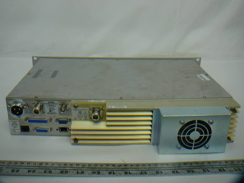
OKRMX800TRV
Nov 22, 2011MX800- Base Station
Equipment Class
TNB - Licensed Non-Broadcast Station Transmitter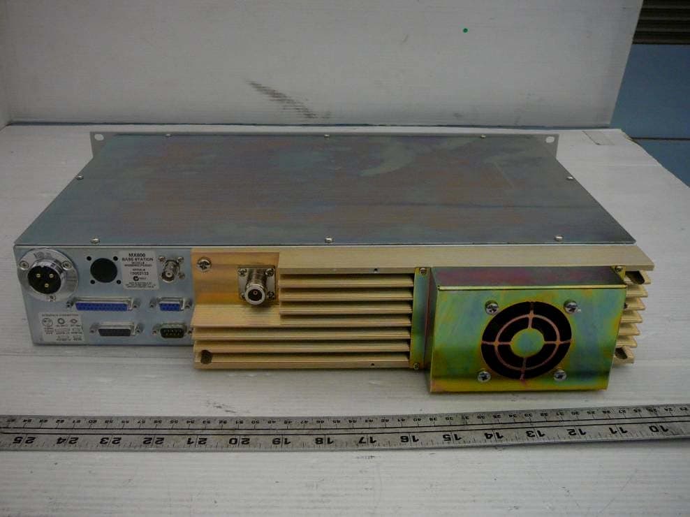
OKRMX800WL
Nov 01, 2010MX800- Base Station
Equipment Class
TNB - Licensed Non-Broadcast Station Transmitter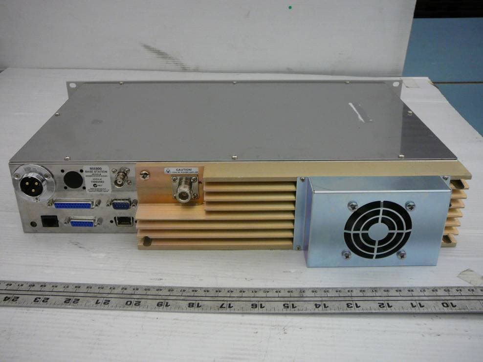
OKRMX800NOPV
Oct 13, 2010MX800- Base Station
Equipment Class
TNB - Licensed Non-Broadcast Station Transmitter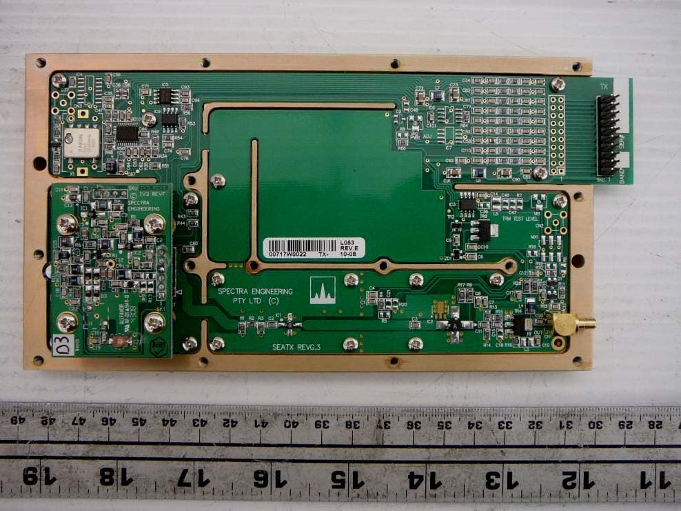
OKRMX800D3V
Oct 11, 2010MX800 - Base Station
Equipment Class
TNB - Licensed Non-Broadcast Station Transmitter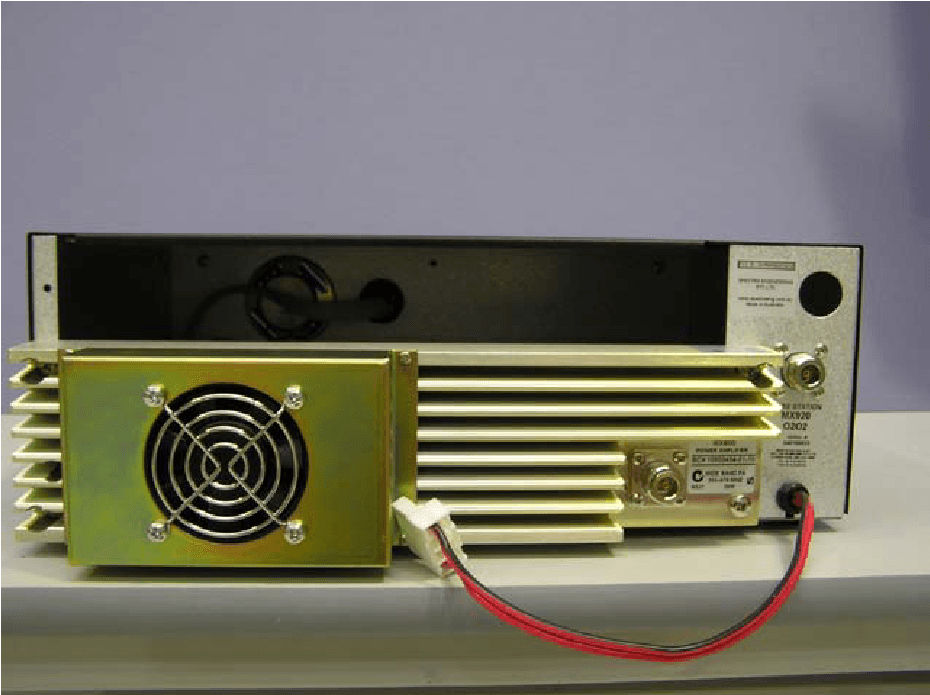
OKRMX920
Jun 05, 2004Desktop Base Station/Repeater
Equipment Class
TNB - Licensed Non-Broadcast Station Transmitter