OKRMX800NOPVMX800- Base Station
Spectra Engineering PTY LTD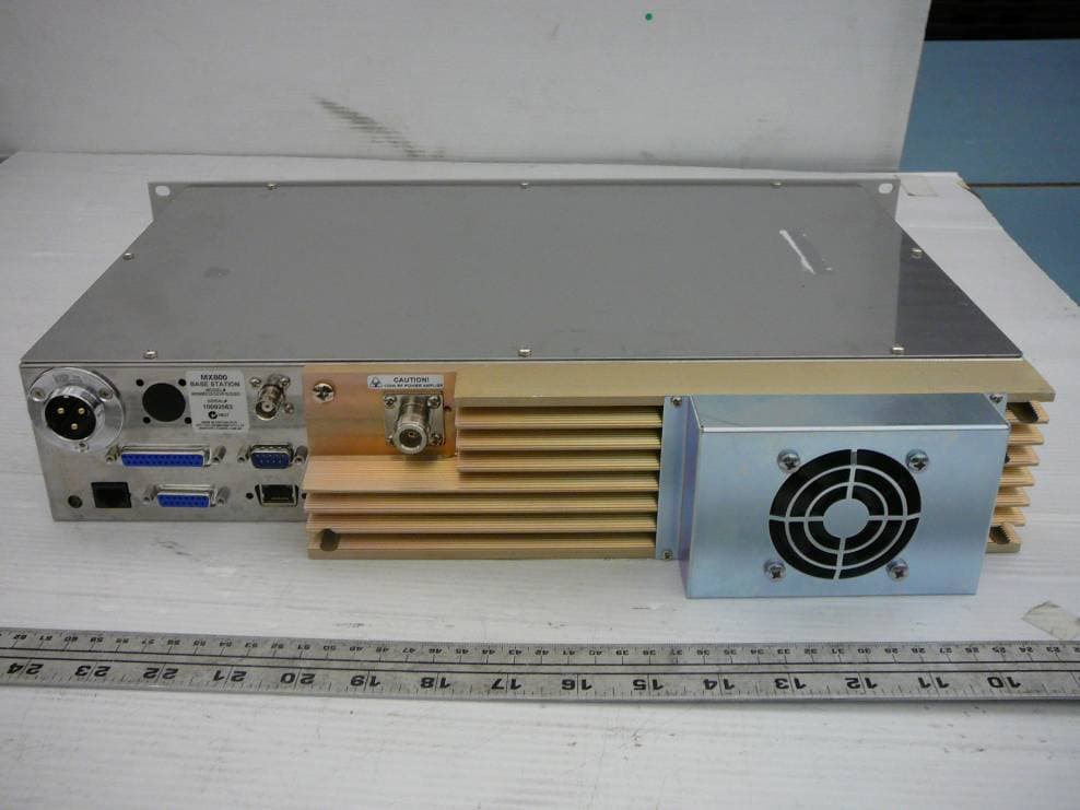
Click to zoom
Application Details
- Equipment Class
- TNB - Licensed Non-Broadcast Station Transmitter
- Date of Grant
- Oct 13, 2010
- Application Purpose
- Original Equipment
- Date of Application
- Oct 13, 2010
- Equipment Note
- MX800- Base Station
- Frequency Range
- 400.00000000 - 485.00000000
- Company
- Spectra Engineering PTY LTD
- Country
- Australia
Documents & Files
Document Text
Text extracted from the exhibit documents filed with the FCC. Open a document above to read the original.
Users Manual
VOLUME (OPTIONAL‐T13) Rotate the volume control clockwise to adjust the volume control for a comfortable listening level. If no sound is heard, temporarily un-mute the radio by briefly rotating the Squelch Control full anti- clockwise. You can adjust the volume by listening to the receiver's background noise. When finished, return squelch setting. (See section on setting Squelch.) CHANNEL SELECTING (OPTIONAL‐T14) Push to select the memory channel number for the selected readout. The channel display will Rotate and select the higher channel when the up button is pressed. By pressing the down button the Channel display will rotate to display the lower channel selected. The selected channel is displayed. SQUELCH (Front panel option‐T13) The squelch is used to eliminate any annoying background noise when there are no signals present. This control is located on the main controller motherboard (RV6) an optional model can have it fitted on the front panel. A technicians tuning tool will be required to adjust this setting. (Factory set for 8dB SINAD) When no signal is received, rotate the Squelch control (SQL) fully counterclockwise first, and then rotate SQL clockwise to the point that the noise just disappears. This will provide optimum Squelch performance. When the Squelch is Open, the receiver's background noise can be heard and 'Amber RX LED' is lit on the front panel display. When the Squelch is closed, the receiver remains quiet when there are no signals present but any incoming signals will override the Squelch and be heard in the speaker. NOTE: If an incoming signal is very weak and is close to the minimum squelch level, it may become broken or “chopped” by the squelch action. To prevent this, simply open the squelch to allow the signal to be heard clearly. Alternatively, you can reduce the squelch sensitivity as described above. When CTCSS is enabled the channel remains quiet until someone transmits using the same tone, and the 'Green Tone LED' lamp will be lit. When the transmission ends, the channel becomes quiet again. By using different tones, several groups of people can share the same channel without disturbing each other. ACCESSORY SWITCH (Depends on Options) The Accessory button is a programmable momentary switch. Which is assigned a function in software programming. (Subject to Radios firmware) See Dealer for application notes for further information on this feature. REPEATER MODE In repeater mode, the received signal is processed and retransmits at a different frequency. Repeaters are usually located on hills, mountains or tall buildings. The increased elevation greatly improves the range of the repeater beyond that of a normal base or Mobile. This means that the repeaters are able to receive and retransmit signals to radios that would otherwise be out of range of each other. To enable the Repeater Function (TTR) the operating channel will required to be programmed as a repeater and User Dip Switch2-4 enable on motherboard. Receiving A Call With the MX800 powered ‘ON’ the front panel Green led is lit. • Set the audio and squelch levels as per SQUELCH and VOLUME section. • Select the desired receiving channel as per Channel selecting section. • When receiving a signal the ‘Amber RX LED‘ indicator lights green when the squelch is open, and audio is emitted from the speaker. • Listen for your call sign when you hear activity, and reply promptly by identifying yourself if called. (For example: Base receiving). Transmitting To Making A Call With the MX800 powered ‘ON’ the front panel Green led is lit. • Select the desired channel, as previously described. • If the ‘Amber RX LED' indicator is on, the channel is busy and you must wait until it is free, before proceeding. If you attempt to transmit anyway, the other party may not receive your transmitted signal. • Lift the microphone off-hook and listen to check that no one else is using the channel. You may also have to press the Monitor Key on the desktop Microphone or the Accessory button on the radio briefly, depending on the microphone used and the options programmed to your radio. • When using the Hand-Held microphone, Hold it about 5cm from your mouth and press the Press-To-Talk (PTT) key, located on the side of the microphone (see Figure 3-1). Speak clearly into the microphone at your normal voice level, identifying yourself by your call sign, and the person you wish to contact. (For example: Base to Mobile 2.). • The ‘Red RX LED’ indicator lights while transmitting. • Release the PTT key when you have finished talking. Transmit Timer Your MX800 is fitted with a preprogrammed timer to limit the maximum length of transmissions. When the time limit is reached, the transmission is terminated. (Subject to Radio Firmware) Illustration only. Microphone not included 00 00 UP CHANNEL UP CHANNEL DOWN CHANNEL DOWN CHANNEL TEN UNITS UNITS PTT PTT Figure 3-1 Fi gure 3-2 __________________________________________________________________________________________ © SPECTRA ENGINEERING 2009 Revision 1.0.3 Unpacking The MX800 Radio is securely packed for transport with special foam packers within a pasteboard container. Before unpacking the MX800 radio, please inspect the MX800 & packaging for signs of damage and report any damage to your MX800 distributor. Upon unpacking of the MX800 radio, please ensure that all items shipped were received, report any missing items to your MX800 distributor. All ports on the rear of the radio should be carefully examined to ensure that packaging has not become wedged inside them. It is very important to examine the fan, as operation of the radio will be affected if any packaging or shipping damage causes the fan to stop working. Installing the Base Station System The design of the MX800 allows it to be installed in a 19inch rack. If you intend to install the radio in an equipment rack consult the supplier’s instructions for your system. Ensure that it is in a secure, dry location with sufficient air space ar…
Text truncated - open the document above for the full version.
Cover Letter(s)
Long Term Confidentiality Request September 24, 2010 To: Federal Communications Commission Authorization and Evaluation Division 7435 Oakland Mills Rd. Columbia, MD 21046 Dear Sir or Madam: Reference FCC ID : OKRMX800NOPV Organization: Spectra Engineering Pty Ltd. Long Term Confidentiality Spectra Engineering requests that the following materials be withheld from public inspection permanently under 47 C.F.R. 0.457 & 0.459: (1) Detailed Circuit Schematics of the EUT (2) Parts List (BOM) (3) Block Diagrams The above materials contain proprietary and confidential information not customarily released to the public. The public disclosure of these materials provides unjustified benefits to its competitors in the market. They are considered confidential trade secrets. Please contact me should there be a need for any additional clarification or information. Best Regards, AJChadd FOR AND ON BEHALF OF SPECTRA ENGINEERING Pty Ltd Anthony Chadd Research & Development Engineer Friday, September 24, 2010 SPECTRA ENGINEERING Pty Ltd “High Performance Base Stations and Repeaters” 9 Trade Road, Malaga 6090 Western Australia Telephone: +61‐8‐92482755 Facsimile: +61‐8‐92482756 e‐Mail: [email protected] Web page: www.spectraeng.com.au
Cover Letter(s)
SPECTRA ENGINEERING Pty Ltd “High Performance Base Stations and Repeaters” 9 Trade Road, Malaga 6090 Western Australia Telephone: +61‐8‐92482755 Facsimile: +61‐8‐92482756 e‐Mail: [email protected] Web page: www.spectraeng.com.au DECLARATION OF SIMILARITY August 20, 2010 To: Bay Area Compliance Laboratories Corp. 1274 Anvilwood Ave. Sunnyvale, CA 94089 Phone: 408-732-9162, Fax: 408-732-9164 http://www.baclcorp.com Dear Sir or Madam: We Spectra Engineering Pty Ltd hereby declare that product: ase Station T: MX800‐Radio Bransceiver \Repeater, Model(s) MX800D3D3V MX800NNV 148‐174MHz 100W VHF 395‐430MHz 100W UHF MX800N2N2V MX800OOV 400‐435MHz 100W UHF 425‐460MHz 100W UHF MX800O2O2V MX800PPV MX800P2P2V MX800P3P3V 435‐470MHz 100W UHF 455‐490MHz 100W UHF 450‐485MHz 100W UHF 475‐495MHz 100W UHF These models are electrically identical with the same electromagnetic emissions and electromagnetic compatibility characteristics as model: MX800D3D3V (100W VHF) and MX800P2P2V (100W UHF) tested by BACL. Descriptions of the differences between the tested model and those that are declared similar are as follows: The MX800 product is made up of four modular components RX, TX, PA Motherboard. For this reason the MX800 Performance approval testing has been carried out under a product family. The fundamental circuit parameter that form the RF parameters are unchanged between model, only minor changes to resistor and capacitor values are done to form product bandwidths (Switching Range). Please contact me should there be need for any additional clarification or information. Best Regards, AJChadd FOR AND ON BEHALF Anthony Chadd OF SPECTRA ENGINEERING Pty Ltd Research & Development Engineer Friday, August 20, 2010 BACL-NF0028-A
External Photos
Spectral Engineering Pty Ltd. FCC ID: OKRMX800NOPV, IC: 5605A-MX800UHFV Report No.: R1009097B-90 Page 70 of 94 FCC Part 90 & IC RSS-119 Test Report 15 EXHIBIT C - EUT Photographs 15.1 EUT (400-435 MHz Band) - Top View 15.2 EUT (400-435 MHz Band) – Bottom View Spectral Engineering Pty Ltd. FCC ID: OKRMX800NOPV, IC: 5605A-MX800UHFV Report No.: R1009097B-90 Page 71 of 94 FCC Part 90 & IC RSS-119 Test Report 15.3 EUT (400-435 MHz Band) – Front View 15.4 EUT (400-435 MHz Band) – Rear View Spectral Engineering Pty Ltd. FCC ID: OKRMX800NOPV, IC: 5605A-MX800UHFV Report No.: R1009097B-90 Page 72 of 94 FCC Part 90 & IC RSS-119 Test Report 15.5 EUT (400-435 MHz Band) – Side View 1 15.6 EUT (400-435 MHz Band) – Side View 2 Spectral Engineering Pty Ltd. FCC ID: OKRMX800NOPV, IC: 5605A-MX800UHFV Report No.: R1009097B-90 Page 73 of 94 FCC Part 90 & IC RSS-119 Test Report 15.7 EUT (435-470 MHz Band) - Top View 15.8 EUT (435-470 MHz Band) – Bottom View Spectral Engineering Pty Ltd. FCC ID: OKRMX800NOPV, IC: 5605A-MX800UHFV Report No.: R1009097B-90 Page 74 of 94 FCC Part 90 & IC RSS-119 Test Report 15.9 EUT (435-470 MHz Band) – Front View 15.10 EUT (435-470 MHz Band) – Rear View Spectral Engineering Pty Ltd. FCC ID: OKRMX800NOPV, IC: 5605A-MX800UHFV Report No.: R1009097B-90 Page 75 of 94 FCC Part 90 & IC RSS-119 Test Report 15.11 EUT (435-470 MHz Band) – Side View 1 15.12 EUT (435-470 MHz Band) – Side View 2 Spectral Engineering Pty Ltd. FCC ID: OKRMX800NOPV, IC: 5605A-MX800UHFV Report No.: R1009097B-90 Page 76 of 94 FCC Part 90 & IC RSS-119 Test Report 15.13 EUT (450-485 MHz Band) - Top View 15.14 EUT (450-485 MHz Band) – Bottom View Spectral Engineering Pty Ltd. FCC ID: OKRMX800NOPV, IC: 5605A-MX800UHFV Report No.: R1009097B-90 Page 77 of 94 FCC Part 90 & IC RSS-119 Test Report 15.15 EUT (450-485 MHz Band) – Front View 15.16 EUT (450-485 MHz Band) – Rear View Spectral Engineering Pty Ltd. FCC ID: OKRMX800NOPV, IC: 5605A-MX800UHFV Report No.: R1009097B-90 Page 78 of 94 FCC Part 90 & IC RSS-119 Test Report 15.17 EUT (450-485 MHz Band) – Side View 1 15.18 EUT (450-485 MHz Band) – Side View 2
ID Label/Location Info
Spectral Engineering Pty Ltd. FCC ID: OKRMX800NOPV, IC: 5605A-MX800UHFV Report No.: R1009097B-90 Page 63 of 94 FCC Part 90 & IC RSS-119 Test Report 13 EXHIBIT A - FCC ID & IC Labeling Requirements 13.1 FCC ID Label Requirement Per FCC Part 2.925, (a) Each equipment covered in an application for equipment authorization shall bear a nameplate or label listing the following: (1) FCC Identifier consisting of the two elements in the exact order specified in §2.926. The FCC Identifier shall be preceded by the term FCC ID in capital letters on a single line, and shall be of a type size large enough to be legible without the aid of magnification. Example: FCC ID: XXX123. XXX—Grantee Code 123—Equipment Product Code 13.2 IC Labeling Requirements As per IC RSS-Gen §5.2, the certification number should appear as follows: IC: XXXXXX-YYYYYYYY Where: • "XXXXXX-YYYYYYYY" is the certification number • "XXXXXX" is the Certificate Holder Number (CHN), made of at most 6 alphanumeric characters (A-Z, 0- 9), assigned by Industry Canada; and • "YYYYYYYY" is the Unique Product Number (UPN), made of at most 11 alphanumeric characters (A-Z, 0-9) assigned by the applicant. • Note 1: The term "IC" before the equipment certification number only signifies that the Industry Canada technical specifications were met. • Note 2: Note 1 shall be conspicuously placed in the equipment user manual. • Note 3: Permitted alphanumeric characters used in the CHN and UPN are limited to capital letters (A-Z) and digits (0-9). Other characters, such as "#", "/" or "-", shall not be used. 13.3 FCC and IC Label Content Model: MX800N2N2V Model: MX800O2O2V Model: MX800P2P2V Spectral Engineering Pty Ltd. FCC ID: OKRMX800NOPV, IC: 5605A-MX800UHFV Report No.: R1009097B-90 Page 64 of 94 FCC Part 90 & IC RSS-119 Test Report 13.4 FCC ID and IC Label Location on EUT Model: MX800N2N2V Model: MX800O2O2V Model: MX800P2P2V
Internal Photos
Spectral Engineering Pty Ltd. FCC ID: OKRMX800NOPV, IC: 5605A-MX800UHFV Report No.: R1009097B-90 Page 79 of 94 FCC Part 90 & IC RSS-119 Test Report 15.19 EUT (400-435 MHz Band) - Digital PCB Board 1 Top View 15.20 EUT (400-435 MHz Band) - Digital PCB Board 1 Bottom View Spectral Engineering Pty Ltd. FCC ID: OKRMX800NOPV, IC: 5605A-MX800UHFV Report No.: R1009097B-90 Page 80 of 94 FCC Part 90 & IC RSS-119 Test Report 15.21 EUT (400-435 MHz Band) - Digital PCB Board 2 Top View 15.22 EUT (400-435 MHz Band) - Digital PCB Board 2 Bottom View Spectral Engineering Pty Ltd. FCC ID: OKRMX800NOPV, IC: 5605A-MX800UHFV Report No.: R1009097B-90 Page 81 of 94 FCC Part 90 & IC RSS-119 Test Report 15.23 EUT (400-435MHz Band) - Digital PCB Board 3 Top View 15.24 EUT (400-435 MHz Band) - Digital PCB Board 3 Bottom View Spectral Engineering Pty Ltd. FCC ID: OKRMX800NOPV, IC: 5605A-MX800UHFV Report No.: R1009097B-90 Page 82 of 94 FCC Part 90 & IC RSS-119 Test Report 15.25 EUT (400-435 MHz Band) - RF PCB Board 1Top View 15.26 EUT (400-435 MHz Band) - RF PCB Board 1 Bottom View Spectral Engineering Pty Ltd. FCC ID: OKRMX800NOPV, IC: 5605A-MX800UHFV Report No.: R1009097B-90 Page 83 of 94 FCC Part 90 & IC RSS-119 Test Report 15.27 EUT (400-435 MHz Band) - RF PCB Board 2Top View 15.28 EUT (400-435 MHz Band) - RF PCB Board 2 Bottom View Spectral Engineering Pty Ltd. FCC ID: OKRMX800NOPV, IC: 5605A-MX800UHFV Report No.: R1009097B-90 Page 84 of 94 FCC Part 90 & IC RSS-119 Test Report 15.29 EUT (435-470 MHz Band) - Digital PCB Board 1 Top View 15.30 EUT (435-470 MHz Band) - Digital PCB Board 1 Bottom View Spectral Engineering Pty Ltd. FCC ID: OKRMX800NOPV, IC: 5605A-MX800UHFV Report No.: R1009097B-90 Page 85 of 94 FCC Part 90 & IC RSS-119 Test Report 15.31 EUT (435-470 MHz Band) - Digital PCB Board 2 Top View 15.32 EUT (435-470 MHz Band) - Digital PCB Board 2 Bottom View Spectral Engineering Pty Ltd. FCC ID: OKRMX800NOPV, IC: 5605A-MX800UHFV Report No.: R1009097B-90 Page 86 of 94 FCC Part 90 & IC RSS-119 Test Report 15.33 EUT (435-470 MHz Band) - Digital PCB Board 3 Top View 15.34 EUT (435-470 MHz Band) - Digital PCB Board 3 Bottom View Spectral Engineering Pty Ltd. FCC ID: OKRMX800NOPV, IC: 5605A-MX800UHFV Report No.: R1009097B-90 Page 87 of 94 FCC Part 90 & IC RSS-119 Test Report 15.35 EUT (435-470 MHz Band) - RF PCB Board 1Top View 15.36 EUT (435-470 MHz Band) - RF PCB Board 1 Bottom View Spectral Engineering Pty Ltd. FCC ID: OKRMX800NOPV, IC: 5605A-MX800UHFV Report No.: R1009097B-90 Page 88 of 94 FCC Part 90 & IC RSS-119 Test Report 15.37 EUT (435-470 MHz Band) - RF PCB Board 2Top View 15.38 EUT (435-470 MHz Band) - RF PCB Board 2 Bottom View Spectral Engineering Pty Ltd. FCC ID: OKRMX800NOPV, IC: 5605A-MX800UHFV Report No.: R1009097B-90 Page 89 of 94 FCC Part 90 & IC RSS-119 Test Report 15.39 EUT (450-485 MHz Band) - Digital PCB Board 1 Top View 15.40 EUT (450-485 MHz Band) - Digital PCB Board 1 Bottom View Spectral Engineering Pty Ltd. FCC ID: OKRMX800NOPV, IC: 5605A-MX800UHFV Report No.: R1009097B-90 Page 90 of 94 FCC Part 90 & IC RSS-119 Test Report 15.41 EUT (450-485 MHz Band) - Digital PCB Board 2 Top View 15.42 EUT (450-485 MHz Band) - Digital PCB Board 2 Bottom View Spectral Engineering Pty Ltd. FCC ID: OKRMX800NOPV, IC: 5605A-MX800UHFV Report No.: R1009097B-90 Page 91 of 94 FCC Part 90 & IC RSS-119 Test Report 15.43 EUT (450-485 MHz Band) - Digital PCB Board 3 Top View 15.44 EUT (450-485 MHz Band) - Digital PCB Board 3 Bottom View Spectral Engineering Pty Ltd. FCC ID: OKRMX800NOPV, IC: 5605A-MX800UHFV Report No.: R1009097B-90 Page 92 of 94 FCC Part 90 & IC RSS-119 Test Report 15.45 EUT (450-485 MHz Band) - RF PCB Board 1Top View 15.46 EUT (450-485 MHz Band) - RF PCB Board 1 Bottom View Spectral Engineering Pty Ltd. FCC ID: OKRMX800NOPV, IC: 5605A-MX800UHFV Report No.: R1009097B-90 Page 93 of 94 FCC Part 90 & IC RSS-119 Test Report 15.47 EUT (450-485 MHz Band) - RF PCB Board 2Top View 15.48 EUT (450-485 MHz Band) - RF PCB Board 2 Bottom View
Test Report
Note: This test report is prepared for the customer shown above and for the device described herein. It may not be duplicated or used in part without prior written consent from Bay Area Compliance Laboratories Corp. This report must not be used by the customer to claim product certification, approval, or endorsement by NVLAP*, NIST, or any agency of the Federal Government. * This report may contain data that are not covered by the NVLAP accreditation and are marked with an asterisk “*” (Rev.2) FCC PART 90 IC RSS-119, ISSUE 10, APRIL 2010 TEST AND MEASUREMENT REPORT For Spectra Engineering Pty Ltd. 9 Trade Road, Malaga, WA 6090, Australia FCC ID: OKRMX800NOPV IC: 5605A-MX800UHFV Report Type: Original Report Product type: UHF Radio Base Stations Test Engineer: Dennis Huang Report Number: R1009097-90 Report Date: 2010-10-06 Reviewed By: Victor Zhang RF Lead Prepared By: (84) Bay Area Compliance Laboratories Corp. 1274 Anvilwood Avenue, Sunnyvale, CA 94085, U.S.A. Tel: (408) 732-9162 Fax: (408) 732 9164 Spectra Engineering Pty Ltd. FCC ID: OKRMX800NOPV, IC: 5605A-MX800UHFV Report No.: R1009097B-90 Page 2 of 94 FCC Part 90 & IC RSS-119 Test Report TABLE OF CONTENTS 1. General Information.............................................................................................................................................6 1.1 PRODUCT DESCRIPTION FOR EQUIPMENT UNDER TEST (EUT) ........................................................................6 1.2 MECHANICAL DESCRIPTION............................................................................................................................6 1.3 OBJECTIVE......................................................................................................................................................6 1.4 RELATED SUBMITTAL(S)/GRANT(S)................................................................................................................6 1.5 TEST METHODOLOGY.....................................................................................................................................6 1.6 MEASUREMENT UNCERTAINTY.......................................................................................................................7 1.7 TEST FACILITY................................................................................................................................................7 2 System Test Configuration...................................................................................................................................8 2.1 JUSTIFICATION................................................................................................................................................8 2.2 EQUIPMENT MODIFICATIONS..........................................................................................................................8 2.3 INTERNAL CONFIGURATION............................................................................................................................8 2.4 LOCAL SUPPORT EQUIPMENT..........................................................................................................................8 2.5 LOCAL SUPPORT EQUIPMENT POWER SUPPLY AND LINE FILTERS..................................................................9 2.6 INTERFACE PORTS AND CABLING....................................................................................................................9 2.7 TEST SETUP BLOCK DIAGRAM........................................................................................................................9 3 Summary of Test Results....................................................................................................................................11 4 FCC §2.1091 & IC RSS-102 - RF Exposure .....................................................................................................12 4.1 APPLICABLE STANDARDS.............................................................................................................................12 4.2 RESULT.........................................................................................................................................................13 5 FCC §2.1046, §90.205 & IC RSS-119 §5.4 – Conducted Output Power ........................................................14 5.1 APPLICABLE STANDARD...............................................................................................................................14 5.2 TEST PROCEDURE.........................................................................................................................................14 5.3 TEST ENVIRONMENTAL CONDITIONS............................................................................................................14 5.4 TEST EQUIPMENT LIST AND DETAILS............................................................................................................14 5.5 TEST RESULT................................................................................................................................................15 6 FCC §2.1047, §90.207 & IC RSS-119 §5.2 – Modulation Characteristic .......................................................16 6.1 APPLICABLE STANDARD...............................................................................................................................16 6.2 TEST PROCEDURE.........................................................................................................................................16 6.3 TEST ENVIRONMENTAL CONDITIONS............................................................................................................16 6.4 TEST EQUIPMENT LIST AND DETAILS............................................................................................................16 6.5 TEST RESULT..............................................................................................................................................…
Text truncated - open the document above for the full version.
Test Setup Photos
Spectral Engineering Pty Ltd. FCC ID: OKRMX800NOPV, IC: 5605A-MX800UHFV Report No.: R1009097B-90 Page 65 of 94 FCC Part 90 & IC RSS-119 Test Report 14 EXHIBIT B - Test Setup Photographs 14.1 Below 1 GHz Radiated Emission – Front View 14.2 Below 1 GHz Radiated Emission – Rear View Spectral Engineering Pty Ltd. FCC ID: OKRMX800NOPV, IC: 5605A-MX800UHFV Report No.: R1009097B-90 Page 66 of 94 FCC Part 90 & IC RSS-119 Test Report 14.3 Above 1 GHz Radiated Emission – Front View 14.4 Above 1 GHz Radiated Emission – Rear View Spectral Engineering Pty Ltd. FCC ID: OKRMX800NOPV, IC: 5605A-MX800UHFV Report No.: R1009097B-90 Page 67 of 94 FCC Part 90 & IC RSS-119 Test Report 14.5 Receiving Spurious Emission 30 MHz to 1GHz - Front View 14.6 Receiving Spurious Emission 30 MHz to1 GHz - Rear View Spectral Engineering Pty Ltd. FCC ID: OKRMX800NOPV, IC: 5605A-MX800UHFV Report No.: R1009097B-90 Page 68 of 94 FCC Part 90 & IC RSS-119 Test Report 14.7 Receiving Spurious Emission above 1 GHz - Front View 14.8 Receiving Spurious Emission above 1 GHz - Rear View Spectral Engineering Pty Ltd. FCC ID: OKRMX800NOPV, IC: 5605A-MX800UHFV Report No.: R1009097B-90 Page 69 of 94 FCC Part 90 & IC RSS-119 Test Report 14.9 Bench Test View 14.10 Temparature Chamber Testing View
Contact Information
Applicant
Gary Jacobs(Managing Director)
Test Firm
Bay Area Compliance LaboratoryJohn Chan
Technical Specifications
| # | Rule Parts | Frequency Range | Power Output | Emission | Tolerance |
|---|---|---|---|---|---|
| 8 | 9 | 400 MHz - 485 MHz | 110 W | 11K0F9W | 1.5 ppm |
Other Applications from Spectra Engineering PTY LTD
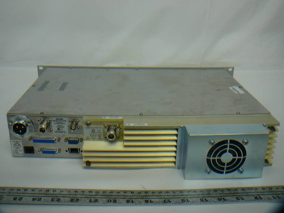
OKRMX800TRV
Nov 22, 2011MX800- Base Station
Equipment Class
TNB - Licensed Non-Broadcast Station Transmitter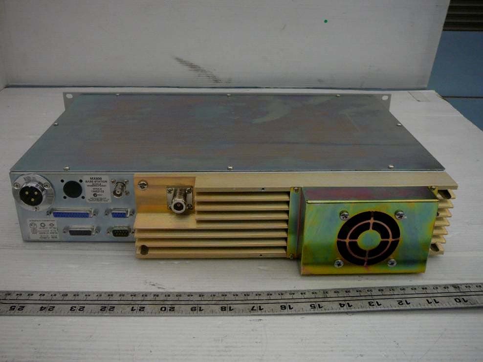
OKRMX800WL
Nov 01, 2010MX800- Base Station
Equipment Class
TNB - Licensed Non-Broadcast Station Transmitter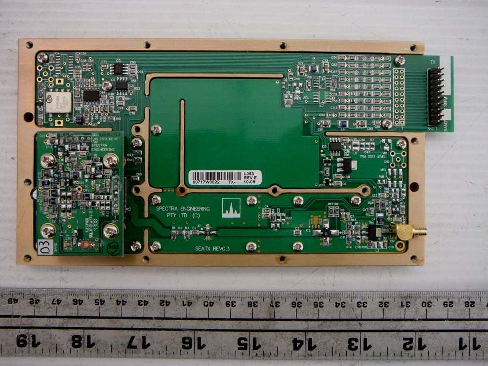
OKRMX800D3V
Oct 11, 2010MX800 - Base Station
Equipment Class
TNB - Licensed Non-Broadcast Station Transmitter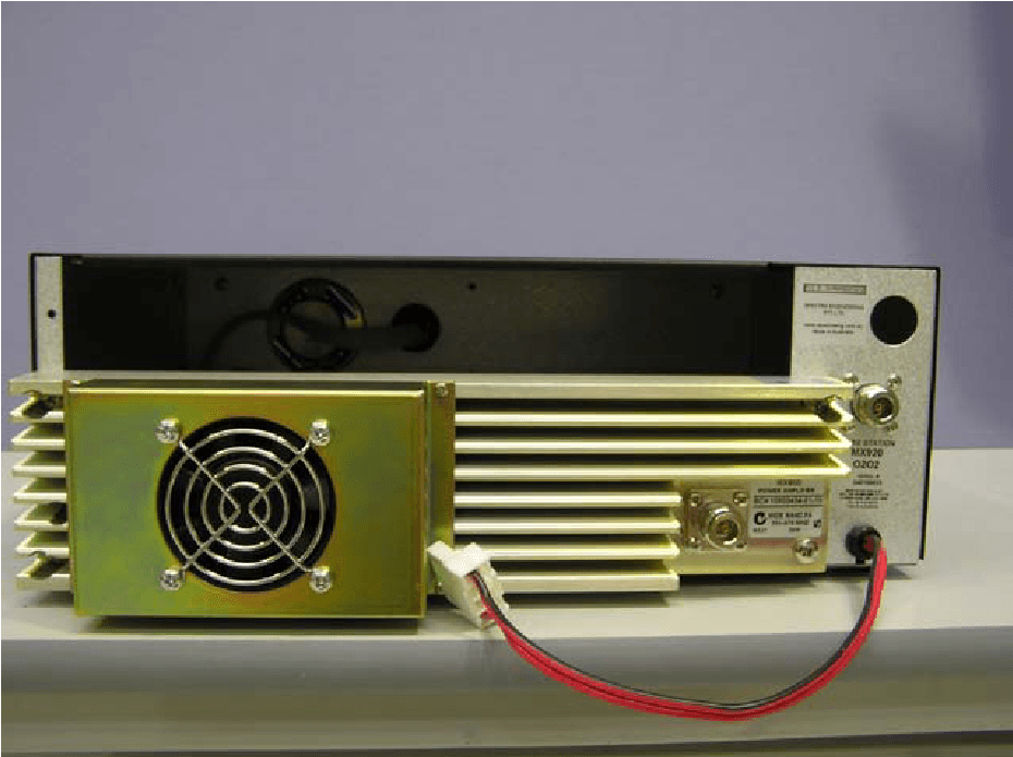
OKRMX920
Jun 05, 2004Desktop Base Station/Repeater
Equipment Class
TNB - Licensed Non-Broadcast Station TransmitterOKRMX800R2R3
Jun 26, 2002RF Base Station/Repeater
Equipment Class
TNB - Licensed Non-Broadcast Station Transmitter