OKRMX800FFRF Base Station
Spectra Engineering PTY LTD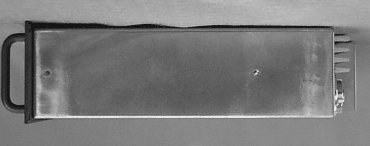
Click to zoom
Application Details
- Equipment Class
- TNB - Licensed Non-Broadcast Station Transmitter
- Date of Grant
- May 27, 2002
- Application Purpose
- Original Equipment
- Date of Application
- Feb 07, 2002
- Equipment Note
- RF Base Station
- Frequency Range
- 220.00000000 - 222.00000000
- Company
- Spectra Engineering PTY LTD
- Country
- Australia
Documents & Files
Document Text
Text extracted from the exhibit documents filed with the FCC. Open a document above to read the original.
Users Manual
4. Technical Description The internal design of the MX800 is of a modular nature allowing for simple configuration and maintenance while ensuring minimal downtime. For reference purposes, the top view of a typical MX800 with top cover removed is shown below. The standard unit without speaker and microphone is illustrated. MX800 top view. PA Module Exciter Module Micro Controller Board Receiver Module 4.1. Exciter Module Refer. Exciter Block Diagram: BD002 Exciter Circuit Diagram: CS002-1 TX VCO Circuit Diagram: CS004-1 (Bands A to Q) RF from the VCO on SKU-1 at a nominal level of+3dBm is applied to the fractional-N synthesizer ICI0 main divider input. This signal is compared with the reference oscillator frequency and the correction voltage from the synthesizers charge pump output is filtered then amplified by the non inverting low noise op amp IC9A. This correction voltage is fed back to the VCO to maintain loop lock as well as being fed to the Micro Controller via SKD-14. A lock detect signal from IC10 is also fed to the Micro Controller via SKD- 16. The op amp uses a 25 volt power supply (generated on the Micro Controller) so as to provide a wide tuning range voltage to the frequency control varicaps located on the VCO board. Frequency programming data for the exciter is sent to the synthesizer chip from the Micro Controller via a serial data line on SKD-18 under the control of the Clock (SKD-15) and Strobe (SKD-17) lines. Provision is made for the optional injection of an external reference frequency. If this option is selected CN3 is fitted and X1 is not fitted. Components R30 and TR7 are also omitted. A second RF output from the VCO on SKT-6 also at +3dBm is used as the main transmit RF amplifier signal source. This main signal is first buffered by a very high isolation circuit consisting ofa 10dB pad and a MMIC amplifier (IC1). The signal is further amplified by IC2 and a variable gain wide band amplifier with 40dB control range and power output of 300mW. The drive power of this stage is used to set the output power to the main power amplifier under the control of the DC voltage on SKD-4 from the Micro Controller board. The VCO boards and synthesizer circuits are the same for the exciter and receiver modules. The VCO consists ofa 10mm ceramic coaxial resonator with common base oscillator for low phase noise for bands 805-960 MHz. Frequencies below 520 MHz use an LC tank circuit. The power supply to the VCO consists of an 8 volt regulator and active filter for maximum noise rejection. It is controlled by the Micro Controller through SKD-7 which connects to switch TR6. For standard modulation, transmit audio is fed on SKD-8 to the conventional point of the VCO varactor. For 2 point modulation, audio is also fed via SKD-19 to the voltage control pin of the VC-TXCO, this in effect cancels out the PLL error that would otherwise have occurred for low audio frequencies, hence resulting in a flat VF response. 4.2. Receiver Module Refer: Receiver Block Diagram: BD001 Receiver Front End Circuit Diagram: CS003-2 Receiver IF Circuit Diagram: CS003-1 RX VCO Circuit Diagram: CS005-1 (Band A to Q) CS012-1 (Band R to X) The receive signal from the antenna enters on CN1 a 3 section Bandpass filter which provides the initial filtering for the front end amplifier. The front end amplifier IC12 is a broad band high performance MMIC with a gain of 18dB, noise figure of 4dB and 3rd order intermodulation intercept of+36dB. This is followed by a 4dB pad and a second 3 section BPF, and a high level double balanced mixer M1. The receiver uses high side local oscillator injection for bands A to I and low side injection for all other bands. RF from the VCO main output on SKT-6 is buffered and amplified to + 17dBm by IC4 and injected in the high level mixer which down converts the signal to the first IF frequency of 90 MHz (45MHz for bands A to D3). This IF signal from the mixer is terminated by a bi-directional constant impedance network and is then amplified by a hipolar amplifier TR2 with a gain of 15dB and 3rd order intermodulation intercept +35dB. This provides a high degree of intermodulation rejection for the receiver. This stage is followed by a 4 pole 90 MHz crystal filter FL3A/B with its associated matching networks. The signal is further amplified and filtered by a transistor amplifier TR3 and its associated 2 pole crystal filter FL4 before being fed into the main IF demodulator chip IC 1 with a second IF frequency of 455kHz. The resulting audio is passed out to the Micro Controller board on SKD-3. The Received Signal Strength Indication (RSSI) from IC1 is buffered by IC5A and connected to the Micro Controller board via SKD-4. RF from the VCO on SKU-1 at a nominal level of+3dBm, is applied to the fractional-N synthesizer (IC10) main divider input. This signal is compared with the reference oscillator frequency and the correction voltage from the synthesizer's charge pump output is filtered then amplified by the non inverting low noise op amp (ICI 1A). This correction voltage is fed back to the VCO to maintain loop lock as well as being fed to the Micro Controller via SKD44. A lock detect signal from IC10 is also fed to the Micro Controller via SKD-I6. The op amp uses a 25 volt power supply (generated on the Micro Controller) so as to provide a wide tuning range voltage to the frequency control varicaps located on the VCO board. Frequency programming data for the receiver is sent to the synthesizer chip from the Micro Controller via the a serial data line on SKD-18 under the control of the Clock (SKD- 15) and Strobe (SKD- 17) lines The local oscillator signal to the mixer is controlled by the Micro Controller through an enable signal on SKD-8. This signal switches the supply to the local oscillator amplifier and is used to enable or disable the receiver. Provision is made for the optional injection of an external reference frequency. If this option is selected CN3 is fitted. 4.3. Power Amplifier Modu…
Text truncated - open the document above for the full version.
Users Manual
5. Alignment and Testing The MX800 test and alignment procedures are divided into two main sections. The first section is a transceiver level procedure which assumes that the radio is fitted with working modules. The second section contains the individual module test procedures. 5.1. Transceiver Setup, Calibration and Alignment This section explains how to setup, calibrate and align the complete MX800 Base Station. A number of procedures are required to fully initialise the MX800. The following test equipment will be needed: 1.0 MXTOOLS (MX800 Base Station Programming Utility) 2.0 MXTOOLS User Manual 3.0 RF Test Set (HP 8920) or equivalent 4.0 CRO (Cathode Ray Oscilloscope) 5.0 RF Power Meter (Watts) 6.0 RF Signal Generator 7.0 Multimeter 8.0 +13.8 VDC @ 15 amp power supply The order of some, but not all, of the procedures is important to ensure correct setup of the radio. The order of the procedures as described is recommended and those that are critical are mentioned. If the radio has been previously setup and the dealer intends to recalibrate and align the radio then steps 5.1.1, 5.1.2 and 5.1.3 can be ignored as the model number, serial number, configuration and channel information will have already been loaded. 5.1.1. Sending Model Number and Serial Number to the Radio The model number is entered or updated using MXTOOLS. To edit the model number select 'Radio Model Number', under the 'Setup' menu. This brings up a dialog box that the dealer can then enter the model number, according to the configuration of the radio. (Refer to the MXTOOLS User Manual for additional help) The dealer cannot alter the serial number as this is factory set. 5.1.2. Sending Configuration Information Firstly the configuration file for the radio needs to be setup. Using MXTOOLS the configuration information needs to be filled out on the Configuration Screen. This information needs to be saved to a configuration file. If an existing radio already contains the desired configuration then this configuration can be downloaded and saved. This configuration information then needs to be 'Sent to the MX800'. (Refer to the MXTOOLS User Manual for additional help) A warning message will appear that indicates that the MX800 Base Station has not yet been calibrated, this may be ignored. Once the configuration information has been sent then all of the programmable parameters within the MX800 Base Station are initialized. 5.1.3. Sending Channel Information The channel information setup is similar to that of the configuration. The channel frequencies, subtones and other parameters are setup in the Channel Screen in MXTOOLS. At this stage it is not necessary to set the values of the digital potentiometers. This will be done in the following procedures. After entering in the channel details this information then needs to be saved to a file. If another radio already contains the desired frequencies then these can be downloaded from that radio and saved to a file. The digital potentiometer values from one radio to the next will differ so it is advisable to save the information in a new channel file and not save over the top of any backup copies of existing radios. The saved channel information is then sent to the MX800. (Refer to the MXTOOLS User Manual for additional help) After sending the configuration and channel information the MX800 is fully programmed and will now operate. Without sending both the configuration and channel information the radio will not function, and thus the following procedures will not be able to be completed. Note: The buttons for sending and loading of channel information may be disabled if MXTOOLS did not successfully 'Connect to MX800'. If this is the case simply choose to 'Connect to the Radio' after the configuration information is sent. 5.1.4. Setting Alignment Channel When setting up the radio it is recommended that all measurement and adjustments are done on a channel that is in the center of the frequency spread of the channels. This minimizes any errors due to frequency changing. Alternatively if the frequency spread of the channels is too large then you may wish to calibrate and align every channel. (In most cases this will not be necessary.) Both individual and group alignment will be covered. The channel may be selected via the Channel Screen in MXTOOLS using the software channel select or in hardware via the internal channel dip switch or via the rear channel select. (Refer to section 2.2.2.3 for additional help.) This channel will then be used when performing the following procedures. 5.1.5. Power Calibration Power calibration affects the forward and reflected power meters on the Diagnostics Screen as well as the low forward power trip point for the MX800. This procedure requires a power meter and the relevant leads to connect the transmitter output to the meter. Power calibration is done using MXTOOLS via the Calibration Screen. To complete the power calibration follow the instructions that MXTOOLS provides. (Refer to the MXTOOLS User Manual for additional help.) Once power calibration has been completed the configuration information must be sent again. Check that the low forward power trip point is set correctly. The calibration affects the low forward power trip point and thus the configuration information must be sent to update it according to the new calibration information. 5.1.6. RSSI Calibration The RSSI calibration is used to calibrate the RSSI meter on the MXTOOLS Diagnostics Screen. The procedure requires an RF signal generator and the relevant leads to connect the signal generator to the RF input of the MX800 Base Station. RSSI calibration is done via the MXTOOLS Calibration Screen. To complete the RSSI calibration follow the instructions that MXTOOLS provides. (Refer to the MXTOOLS User Manual for additional help.) 5.1.7. Temperature Calibration The temperature calibration is used to calibrate the temperature meter on the MXTOOLS Diagnostics Screen and the temperature con…
Text truncated - open the document above for the full version.
Cover Letter(s)
April 11, 2002 Federal Communications Commission FCC ID: OKRMX800FF For m 731 : EA632367 Correspondence Reference: 22532 Dear Sir or Madam: Concerning your request for additional information, Schematics have been regenerated as PDF files and include the following: RX RF Front EndPage one of the receiver schematic RX IFPage two of the receiver schematic RX VCOPlugs into the RX module TX VCOPlugs into the Exciter module ExciterOne page Power AmplifierOne page ControllerSix pages Theor y of Operation had been included in the manual upload. The manual supplied was the ser vice and operator manual (there is only one manual). The section requested was sent again as part of the Theor y of Operation section. A list of active components has been submitted as part of the Parts List and Tuning Infor mation section. The manufacturer has the repair depots use the submitted schematics (which have all the frequency variation part values) as the parts lists. The tuning procedure section of the manual has also been placed into this section. I tr ust this meets the requirements and items requested. Sincerely, Walter C. Simciak Chief Engineer 5481 SAND LAKE DRIVE, MELBOURNE,FLORIDA • 32934 PHONE: 321-255-0329 • FAX: 321-255-0329
Cover Letter(s)
May 7, 2002 Federal Communications Commission Re:FCC ID OKRMX800FF Applicant:Spectra Engineering PTY LTD Correspondence Reference Number: 22783 731 Confirmation Number:EA632367 Dear Andy: Our client, Spectra Engineering PTY LTD has requested that the schematics be held confidential. These exhibits were marked confidential at time of upload. They feel that this information is sensitive for their position in the market place. Sincerely, Walter “Bud” Simciak Chief Engineer, ADRad Communications, Inc. 5481 SAND LAKE DRIVE, MELBOURNE,FLORIDA • 32934 PHONE: 321-255-0329 • FAX: 321-255-0329
External Photos
Front Panel and Exterior Views... FCC ID: OKRMX800FF The MX800 standard front panel is illustrated below. The following table explains the functions of the front panel LEDs which indicate the status of the MX800 in real time. LEDFUNCTION POWERIndicates the power supply voltage is within software selectable limits. RXA signal is being received by the receiver or the receivers squelch is open. TXThe trans mi tter is trans mi tti ng RF power. CTCSSA valid Continuous Tone Coded Squelch Signal has been detected. AUXAux function is selected or the PLL is unlocked. A LAR MA ge neral alarm co ndition e xists. “PMR” variant illustrated below along with view of chassis. Chassis and front panel are metal. Front panel may also be painted black as another variant. POWER RX TX CTCSS AUX ALARM Push-wheel channel change Speaker Digital up/down volume RJ45 Microphone socket Squelch adjust hole Mounting holes for slide rails Sideways airflow permits MX800s to be stacked in a rack. DC Power Input BNC RX Input N Type TX Output Thermally Co ntro lle d Fa n Simplex Relay O/P or N Type RX Input or External Ref Input RJ11 CN1 Line I/O CN4 RS232 CN2 Mo nitor CN3 Digital I/O
ID Label/Location Info
Label information: MX800 Base Station Model # MX800FFXXXXX Serial # ******** Made in Australia SPECTRA EN GIN EERIN G PTY LTD 9 Trade Road, Malaga 6090 FCC ID: OKRMX800FF
ID Label/Location Info
Label information: MX800 Base Station Model # MX800FFXXXXX Serial # ******** Made in Australia SPECTRA EN GIN EERIN G PTY LTD 9 Trade Road, Malaga 6090 FCC ID: OKRMX800FF
Internal Photos
F Frequency Range Power AmplifierF Frequency Range Power Amplifier (Right Side) with Low Pass Filter Shelding
Internal Photos
Logic/Controller Board
Internal Photos
F Frequency Range Receiver Receiver VCO
Internal Photos
‘F’ Frequency Range Exciter w/ VCO ‘F’ Band Exciter VCO
Operational Description
4. Technical Description The internal design of the MX800 is of a modular nature allowing for simple configuration and maintenance while ensuring minimal downtime. For reference purposes, the top view of a typical MX800 with top cover removed is shown below. The standard unit without speaker and microphone is illustrated. MX800 top view. PA Module Exciter Module Micro Controller Board Receiver Module 4.1. Exciter Module Refer. Exciter Block Diagram: BD002 Exciter Circuit Diagram: CS002-1 TX VCO Circuit Diagram: CS004-1 (Bands A to Q) RF from the VCO on SKU-1 at a nominal level of+3dBm is applied to the fractional-N synthesizer ICI0 main divider input. This signal is compared with the reference oscillator frequency and the correction voltage from the synthesizers charge pump output is filtered then amplified by the non inverting low noise op amp IC9A. This correction voltage is fed back to the VCO to maintain loop lock as well as being fed to the Micro Controller via SKD-14. A lock detect signal from IC10 is also fed to the Micro Controller via SKD- 16. The op amp uses a 25 volt power supply (generated on the Micro Controller) so as to provide a wide tuning range voltage to the frequency control varicaps located on the VCO board. Frequency programming data for the exciter is sent to the synthesizer chip from the Micro Controller via a serial data line on SKD-18 under the control of the Clock (SKD-15) and Strobe (SKD-17) lines. Provision is made for the optional injection of an external reference frequency. If this option is selected CN3 is fitted and X1 is not fitted. Components R30 and TR7 are also omitted. A second RF output from the VCO on SKT-6 also at +3dBm is used as the main transmit RF amplifier signal source. This main signal is first buffered by a very high isolation circuit consisting ofa 10dB pad and a MMIC amplifier (IC1). The signal is further amplified by IC2 and a variable gain wide band amplifier with 40dB control range and power output of 300mW. The drive power of this stage is used to set the output power to the main power amplifier under the control of the DC voltage on SKD-4 from the Micro Controller board. The VCO boards and synthesizer circuits are the same for the exciter and receiver modules. The VCO consists ofa 10mm ceramic coaxial resonator with common base oscillator for low phase noise for bands 805-960 MHz. Frequencies below 520 MHz use an LC tank circuit. The power supply to the VCO consists of an 8 volt regulator and active filter for maximum noise rejection. It is controlled by the Micro Controller through SKD-7 which connects to switch TR6. For standard modulation, transmit audio is fed on SKD-8 to the conventional point of the VCO varactor. For 2 point modulation, audio is also fed via SKD-19 to the voltage control pin of the VC-TXCO, this in effect cancels out the PLL error that would otherwise have occurred for low audio frequencies, hence resulting in a flat VF response. 4.2. Receiver Module Refer: Receiver Block Diagram: BD001 Receiver Front End Circuit Diagram: CS003-2 Receiver IF Circuit Diagram: CS003-1 RX VCO Circuit Diagram: CS005-1 (Band A to Q) CS012-1 (Band R to X) The receive signal from the antenna enters on CN1 a 3 section Bandpass filter which provides the initial filtering for the front end amplifier. The front end amplifier IC12 is a broad band high performance MMIC with a gain of 18dB, noise figure of 4dB and 3rd order intermodulation intercept of+36dB. This is followed by a 4dB pad and a second 3 section BPF, and a high level double balanced mixer M1. The receiver uses high side local oscillator injection for bands A to I and low side injection for all other bands. RF from the VCO main output on SKT-6 is buffered and amplified to + 17dBm by IC4 and injected in the high level mixer which down converts the signal to the first IF frequency of 90 MHz (45MHz for bands A to D3). This IF signal from the mixer is terminated by a bi-directional constant impedance network and is then amplified by a hipolar amplifier TR2 with a gain of 15dB and 3rd order intermodulation intercept +35dB. This provides a high degree of intermodulation rejection for the receiver. This stage is followed by a 4 pole 90 MHz crystal filter FL3A/B with its associated matching networks. The signal is further amplified and filtered by a transistor amplifier TR3 and its associated 2 pole crystal filter FL4 before being fed into the main IF demodulator chip IC 1 with a second IF frequency of 455kHz. The resulting audio is passed out to the Micro Controller board on SKD-3. The Received Signal Strength Indication (RSSI) from IC1 is buffered by IC5A and connected to the Micro Controller board via SKD-4. RF from the VCO on SKU-1 at a nominal level of+3dBm, is applied to the fractional-N synthesizer (IC10) main divider input. This signal is compared with the reference oscillator frequency and the correction voltage from the synthesizer's charge pump output is filtered then amplified by the non inverting low noise op amp (ICI 1A). This correction voltage is fed back to the VCO to maintain loop lock as well as being fed to the Micro Controller via SKD44. A lock detect signal from IC10 is also fed to the Micro Controller via SKD-I6. The op amp uses a 25 volt power supply (generated on the Micro Controller) so as to provide a wide tuning range voltage to the frequency control varicaps located on the VCO board. Frequency programming data for the receiver is sent to the synthesizer chip from the Micro Controller via the a serial data line on SKD-18 under the control of the Clock (SKD- 15) and Strobe (SKD- 17) lines The local oscillator signal to the mixer is controlled by the Micro Controller through an enable signal on SKD-8. This signal switches the supply to the local oscillator amplifier and is used to enable or disable the receiver. Provision is made for the optional injection of an external reference frequency. If this option is selected CN3 is fitted. 4.3. Power Amplifier Modu…
Text truncated - open the document above for the full version.
Parts List/Tune Up Info
Active Device List Receiver Module Reference IDPart NumberDiscription M1LRFMS-2-17RF Mixer TR1N/A TR2BFG-591IF Amplifier TR32SC3583IF Amplifier TR4BC-847GP Transistor TR5BC-847DC Filter to VCO TR6BC-847TCXO Buffer X189.545 MHzCrystal X2TCXO1 ppm TCXO IC1NE615IF Amplifier IC278L088 volt regulator IC3LP2951Adjustable regulator IC4MSA-0886LO Buffer IC5MC3302Audio/RSSI Buffer IC6X24C04ROM IC778L055 volt Regulator IC878L055 volt Regulator IC979M08-8 volt Regulator IC10SA7025DKPLL IC IC11OP28FSLow Noise Operational Amplifier IC12SGA-6489RF High Dynamic Range Amp Power Amplifier Module Reference IDPart NumberDiscription TR12SC310250 Watt RF Output Device TR2FZT751PNP PTT Control TR32SJ177FET, Voltage Regulator IC1M68707LRF Power Hybrid IC278L055 Volt Regulator IC378L055 Volt Regulator IC4X24C04ROM IC5LT1123C2Voltage Regulator D1, D2HSMS-2800Forward/Reverse Detector Tx VCO Module Reference IDPart NumberDiscription TR1SST-310FET, Oscillator IC1MAR-6SMRF Amplifier/Buffer IC2MAR-6SMRF Amplifier/Buffer All Components are 0805 SMT D Note: Passive Components per Rx VCO Module Reference IDPart NumberDiscription TR1SST-310FET, Oscillator IC1MAR-6SMRF Amplifier/Buffer IC2MAR-6SMRF Amplifier/Buffer Exciter Module Reference IDPart NumberDiscription TR1N/A TR2BC847GP Transistor, Power Control TR3BC857Bias for TR4 TR4BFG-591RF Buffer Amplifier TR5BC847GP Transistor, PTT TR6BC857GP Transistor, PTT TR7BC847TCXO Buffer TR8FTZ751GP Transistor, Power Control X1TCXO1 ppm IC1MAR-06RF Buffer IC2MAV-11RF Buffer IC378L088 Volt Regulator IC474HC393Frequency Divider IC578L055 Volt Regulator IC6X24C16ROM IC778L055 Volt Regulator IC878L088 Volt Regulator IC9OP284FSLow Noise Op Amp IC10SA7025DKPLL Device Devices Schematic
Parts List/Tune Up Info
5. Alignment and Testing The MX800 test and alignment procedures are divided into two main sections. The first section is a transceiver level procedure which assumes that the radio is fitted with working modules. The second section contains the individual module test procedures. 5.1. Transceiver Setup, Calibration and Alignment This section explains how to setup, calibrate and align the complete MX800 Base Station. A number of procedures are required to fully initialise the MX800. The following test equipment will be needed: 1.0 MXTOOLS (MX800 Base Station Programming Utility) 2.0 MXTOOLS User Manual 3.0 RF Test Set (HP 8920) or equivalent 4.0 CRO (Cathode Ray Oscilloscope) 5.0 RF Power Meter (Watts) 6.0 RF Signal Generator 7.0 Multimeter 8.0 +13.8 VDC @ 15 amp power supply The order of some, but not all, of the procedures is important to ensure correct setup of the radio. The order of the procedures as described is recommended and those that are critical are mentioned. If the radio has been previously setup and the dealer intends to recalibrate and align the radio then steps 5.1.1, 5.1.2 and 5.1.3 can be ignored as the model number, serial number, configuration and channel information will have already been loaded. 5.1.1. Sending Model Number and Serial Number to the Radio The model number is entered or updated using MXTOOLS. To edit the model number select 'Radio Model Number', under the 'Setup' menu. This brings up a dialog box that the dealer can then enter the model number, according to the configuration of the radio. (Refer to the MXTOOLS User Manual for additional help) The dealer cannot alter the serial number as this is factory set. 5.1.2. Sending Configuration Information Firstly the configuration file for the radio needs to be setup. Using MXTOOLS the configuration information needs to be filled out on the Configuration Screen. This information needs to be saved to a configuration file. If an existing radio already contains the desired configuration then this configuration can be downloaded and saved. This configuration information then needs to be 'Sent to the MX800'. (Refer to the MXTOOLS User Manual for additional help) A warning message will appear that indicates that the MX800 Base Station has not yet been calibrated, this may be ignored. Once the configuration information has been sent then all of the programmable parameters within the MX800 Base Station are initialized. 5.1.3. Sending Channel Information The channel information setup is similar to that of the configuration. The channel frequencies, subtones and other parameters are setup in the Channel Screen in MXTOOLS. At this stage it is not necessary to set the values of the digital potentiometers. This will be done in the following procedures. After entering in the channel details this information then needs to be saved to a file. If another radio already contains the desired frequencies then these can be downloaded from that radio and saved to a file. The digital potentiometer values from one radio to the next will differ so it is advisable to save the information in a new channel file and not save over the top of any backup copies of existing radios. The saved channel information is then sent to the MX800. (Refer to the MXTOOLS User Manual for additional help) After sending the configuration and channel information the MX800 is fully programmed and will now operate. Without sending both the configuration and channel information the radio will not function, and thus the following procedures will not be able to be completed. Note: The buttons for sending and loading of channel information may be disabled if MXTOOLS did not successfully 'Connect to MX800'. If this is the case simply choose to 'Connect to the Radio' after the configuration information is sent. 5.1.4. Setting Alignment Channel When setting up the radio it is recommended that all measurement and adjustments are done on a channel that is in the center of the frequency spread of the channels. This minimizes any errors due to frequency changing. Alternatively if the frequency spread of the channels is too large then you may wish to calibrate and align every channel. (In most cases this will not be necessary.) Both individual and group alignment will be covered. The channel may be selected via the Channel Screen in MXTOOLS using the software channel select or in hardware via the internal channel dip switch or via the rear channel select. (Refer to section 2.2.2.3 for additional help.) This channel will then be used when performing the following procedures. 5.1.5. Power Calibration Power calibration affects the forward and reflected power meters on the Diagnostics Screen as well as the low forward power trip point for the MX800. This procedure requires a power meter and the relevant leads to connect the transmitter output to the meter. Power calibration is done using MXTOOLS via the Calibration Screen. To complete the power calibration follow the instructions that MXTOOLS provides. (Refer to the MXTOOLS User Manual for additional help.) Once power calibration has been completed the configuration information must be sent again. Check that the low forward power trip point is set correctly. The calibration affects the low forward power trip point and thus the configuration information must be sent to update it according to the new calibration information. 5.1.6. RSSI Calibration The RSSI calibration is used to calibrate the RSSI meter on the MXTOOLS Diagnostics Screen. The procedure requires an RF signal generator and the relevant leads to connect the signal generator to the RF input of the MX800 Base Station. RSSI calibration is done via the MXTOOLS Calibration Screen. To complete the RSSI calibration follow the instructions that MXTOOLS provides. (Refer to the MXTOOLS User Manual for additional help.) 5.1.7. Temperature Calibration The temperature calibration is used to calibrate the temperature meter on the MXTOOLS Diagnostics Screen and the temperature con…
Text truncated - open the document above for the full version.
Test Report
1 Radiated Emissions Test Report Prepared for ADRad Communications, Inc. November 29, 2001 A. DEVICE UNDER TEST The device is a VHF Repeater operating under Part 90 of the FCC rules. The device is configured as a metal cased, rack mountable unit, powered from an external DC source of 13.8 volts, nominal. The device covers the frequency range of 216.000 MHz. to 222.000 MHz. B. MEASUREMENT PROCEDURE: Radiation measurements were conducted according to the procedures set forth in ANSI C63.4 (1992). The device was tested as follows: The unit was placed on the center of the turntable directly on top of the DC supply. A 50 ohm, 100 watt load termination was connected to the transmitter section output terminal (type N) and an EMCO m…
Text truncated - open the document above for the full version.
Contact Information
Applicant
Gary Jacobs(Managing Director)
Technical Contact
ADRad Communications, IncWalter C Simciak
[email protected]321-255-0329
5481 Sand Lake Drive · Melbourne, Florida · United States
Non-Technical Contact
ADRad Communications, IncWalter C Simciak
[email protected]321-255-0329
Technical Specifications
| # | Rule Parts | Frequency Range | Power Output | Emission | Tolerance |
|---|---|---|---|---|---|
| 4 | 9 | 220 MHz - 222 MHz | 50 W | 11K0F3E | 2.5 ppm |
Other Applications from Spectra Engineering PTY LTD
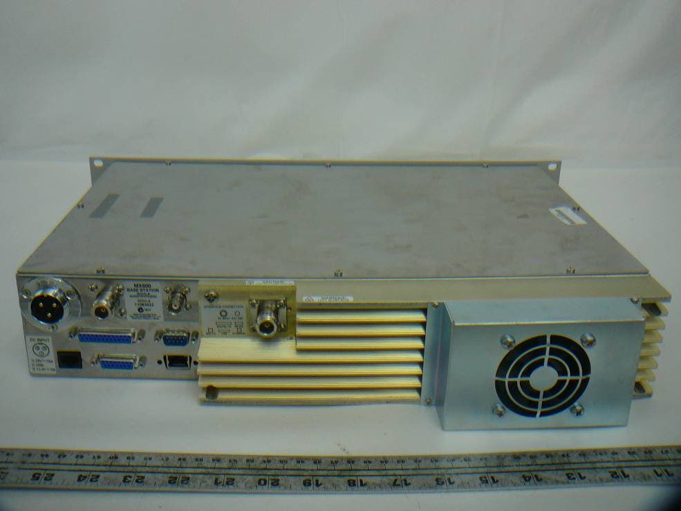
OKRMX800TRV
Nov 22, 2011MX800- Base Station
Equipment Class
TNB - Licensed Non-Broadcast Station Transmitter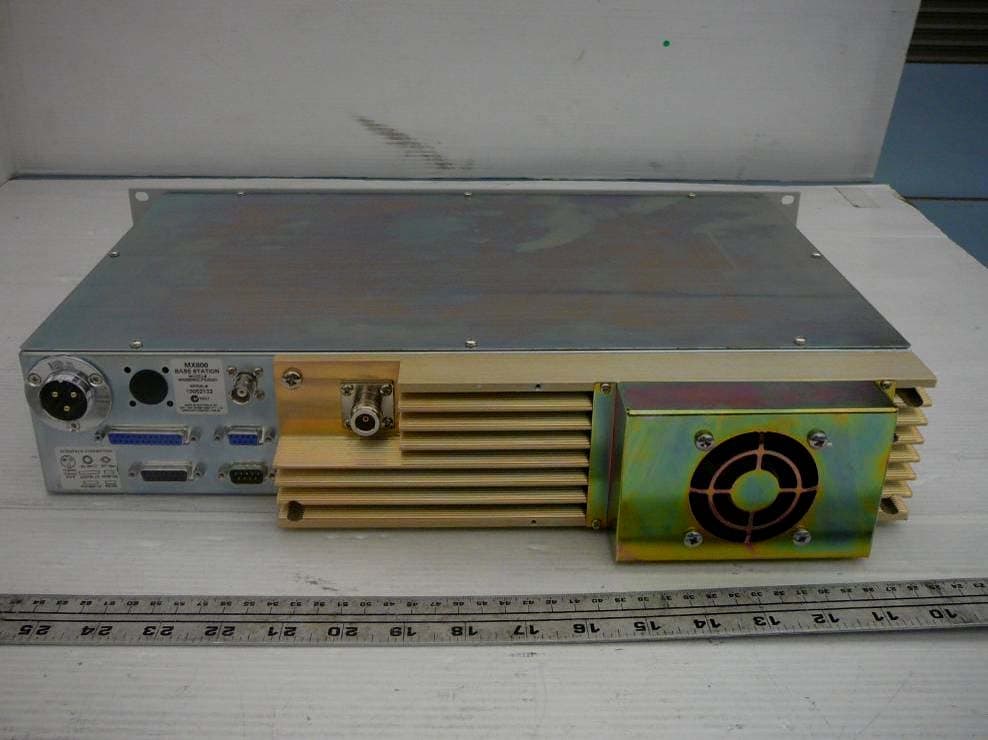
OKRMX800WL
Nov 01, 2010MX800- Base Station
Equipment Class
TNB - Licensed Non-Broadcast Station Transmitter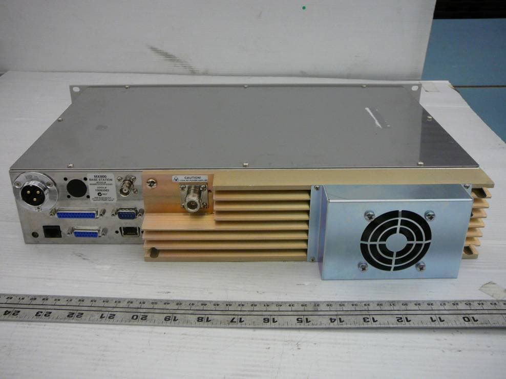
OKRMX800NOPV
Oct 13, 2010MX800- Base Station
Equipment Class
TNB - Licensed Non-Broadcast Station Transmitter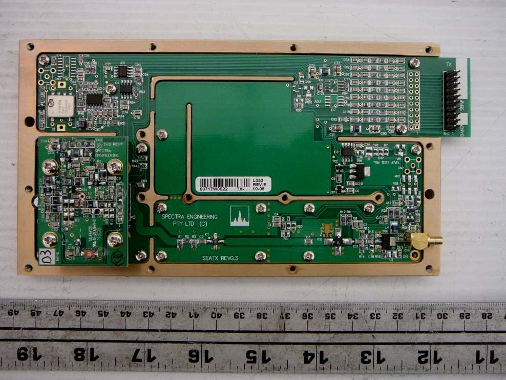
OKRMX800D3V
Oct 11, 2010MX800 - Base Station
Equipment Class
TNB - Licensed Non-Broadcast Station Transmitter
OKRMX920
Jun 05, 2004Desktop Base Station/Repeater
Equipment Class
TNB - Licensed Non-Broadcast Station Transmitter